2001 DODGE RAM nv 3500
[x] Cancel search: nv 3500Page 2 of 2889
INTRODUCTION
TABLE OF CONTENTS
page page
BODY CODE PLATE
DESCRIPTION............................1
FASTENER IDENTIFICATION
DESCRIPTION............................3
FASTENER USAGE
DESCRIPTION............................6
INTERNATIONAL VEHICLE CONTROL &
DISPLAY SYMBOLS
DESCRIPTION............................6
METRIC SYSTEM
DESCRIPTION............................6TORQUE REFERENCES
DESCRIPTION............................9
VECI LABEL
DESCRIPTION...........................10
OPERATION.............................10
VEHICLE IDENTIFICATION NUMBER
DESCRIPTION...........................10
VEHICLE SAFETY CERTIFICATION LABEL
DESCRIPTION...........................12
EQUIPMENT IDENTIFICATION PLATE
DESCRIPTION...........................12
BODY CODE PLATE
DESCRIPTION
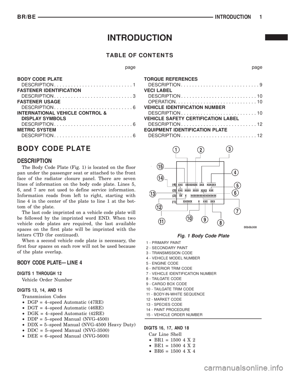
The Body Code Plate (Fig. 1) is located on the floor
pan under the passenger seat or attached to the front
face of the radiator closure panel. There are seven
lines of information on the body code plate. Lines 5,
6, and 7 are not used to define service information.
Information reads from left to right, starting with
line 4 in the center of the plate to line 1 at the bot-
tom of the plate.
The last code imprinted on a vehicle code plate will
be followed by the imprinted word END. When two
vehicle code plates are required, the last available
spaces on the first plate will be imprinted with the
letters CTD (for continued).
When a second vehicle code plate is necessary, the
first four spaces on each row will not be used because
of the plate overlap.
BODY CODE PLATEÐLINE 4
DIGITS 1 THROUGH 12
Vehicle Order Number
DIGITS 13, 14, AND 15
Transmission Codes
²DGP = 4±speed Automatic (47RE)
²DGT = 4±speed Automatic (46RE)
²DGK = 4±speed Automatic (42RE)
²DDP = 5±speed Manual (NVG-4500)
²DDX = 5±speed Manual (NVG-4500 Heavy Duty)
²DDC = 5±speed Manual (NVG-3500)
²DEE = 6±speed Manual (NVG-5600)DIGITS 16, 17, AND 18
Car Line Shell
²BR1=15004X2
²BE1=15004X2
²BR6=15004X4
Fig. 1 Body Code Plate
1 - PRIMARY PAINT
2 - SECONDARY PAINT
3 - TRANSMISSION CODE
4 - VEHICLE MODEL NUMBER
5 - ENGINE CODE
6 - INTERIOR TRIM CODE
7 - VEHICLE IDENTIFICATION NUMBER
8 - TAILGATE CODE
9 - CARGO BOX CODE
10 - TAILGATE TRIM CODE
11 - BODY-IN-WHITE SEQUENCE
12 - MARKET CODE
13 - SPECIES CODE
14 - PAINT PROCEDURE
15 - VEHICLE ORDER NUMBER
BR/BEINTRODUCTION 1
Page 3 of 2889
²BE6=15004X4
²BR2=25004X2
²BE2=25004X2
²BR7=25004X4
²BE7=25004X4
²BR3=35004X2
²BE3=35004X2
²BR8=35004X4
²BE8=35004X4
DIGIT 19
Price Class
²L = Ram Truck (All)
DIGITS 20 AND 21
Body Type
²
31 = Ram Truck Club Cab (138.7 in. Wheel Base)
²32 = Ram Truck Club Cab (154.7 in. Wheel Base)
²33 = Ram Truck Quad Cab (138.7 in. Wheel Base)
²34 = Ram Truck Quad Cab (154.7 in. Wheel Base)
²61 = Ram Truck (118.7 in. Wheel Base)
²62 = Ram Truck (134.7 in. Wheel Base)
²63 = Ram Truck Cab Chassis (138.7 in. Wheel
Base)
²
64 = Ram Truck Cab Chassis (162.7 in. Wheel
Base)
BODY CODE PLATEÐLINE 3
DIGITS 1,2, AND 3
Paint Procedure
²APA = Monotone
²AP9 = Special
²APB = Two-tone (Waterfall)
²APC = Two-tone (Centerband)
²APD = Two-tone (Lower break)
DIGIT 4
Open Space
DIGITS 5 THROUGH 8
Primary Paint
Refer to Group 23, Body for color codes.
DIGIT 9
Open Space
DIGITS 10 THROUGH 13
Secondary Paint
DIGIT 14
Open Space
DIGITS 15 THROUGH 18
Interior Trim CodeDIGIT 19
Open Space
DIGITS 20, 21, AND 22
Engine Code
²EHC = 3.9 L 6 cyl. MPI Gasoline
²ELF = 5.2 L 8 cyl. MPI Gasoline
²ELN = 5.2 L 8 cyl. (CNG)
²EML = 5.9 L 8 cyl. MPI Gasoline
²EMM = 5.9 L 8 cyl. MPI Gasoline (Heavy Duty)
²ETC = 5.9 L 6 cyl. Turbo Diesel
²EWA = 8.0 L 10 cyl. MPI Gasoline
BODY CODE PLATEÐLINE 2
DIGIT 1 Open Space
DIGITS 2 AND 3 Species Code. (Used for Manufacturing)
DIGIT 4
Open Space
DIGIT 5
Market Code
²B = International
²C = Canada
²M = Mexico
²U = United States
DIGIT 6
Open Space
DIGITS 7 THROUGH 23
Vehicle Identification Number (VIN)
Refer to Vehicle Identification Number (VIN) para-
graph for proper breakdown of VIN code.
BODY CODE PLATEÐLINE 1
DIGITS 1 THROUGH 6 Body-in-white assembly sequence.
DIGIT 7
Open Space
DIGIT 8 Tailgate trim code.
DIGIT 9
Open Space
DIGITS 10 THROUGH 12 Cargo box code
²XBS = Sweptline
DIGIT 13
Open Space
2 INTRODUCTIONBR/BE
BODY CODE PLATE (Continued)
Page 12 of 2889
tification Number. The check digit is used by the
manufacturer and government agencies to verify the
authenticity of the vehicle and official documenta-
tion. The formula to use the check digit is not
released to the general public.
POSITION INTERPRETATION CODE = DESCRIPTION
1 Country of Origin 1 = United States
3 = Mexico
2 Make B = Dodge
3 Vehicle Type 6 = Incomplete
7 = Truck
4 Gross Vehicle Weight Rating H = 6001-7000
J = 7001-8000
K = 8001-9000
L = 9001-10,000
M = 10,001-14,000
5 Vehicle Line C = Ram Cab Chassis/Ram Pick Up (4x2)
F = Ram Cab Chassis/Ram Pick Up (4x4)
6 Series 1 = 1500
2 = 2500
3 = 3500
7 Body Style 2 = Club Cab
3 = Quad Cab
6 = Conventional Cab/Cab Chassis
8 Engine 6 = 5.9L 6 cyl. 24 Valve Diesel
7=5.9 6cyl. 24 Valve Turbo Diesel H/O
W = 8.0L 10 cyl. MPI
X = 3.9L 6 cyl. MPI
Y = 5.2L 8 cyl. MPI
Z = 5.9L 8 cyl. MPI-LDC
5 = 5.9L 8cyl. MPI-HDC
9 Check Digit 0 through 9 or X
10 Model Year 1=2001
11 Plant Location J = St. Louis North
S = Dodge City
M = Lago Alberto Assembly
12 thru 17 Vehicle Build Sequence
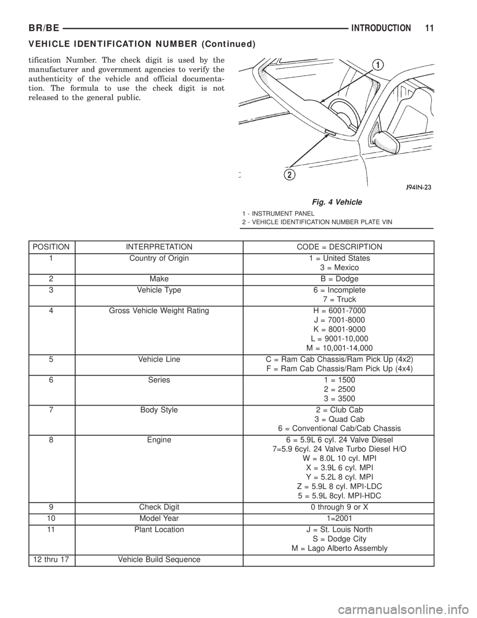
Fig. 4 Vehicle
1 - INSTRUMENT PANEL
2 - VEHICLE IDENTIFICATION NUMBER PLATE VIN
BR/BEINTRODUCTION 11
VEHICLE IDENTIFICATION NUMBER (Continued)
Page 19 of 2889
FLUID CAPACITIES
SPECIFICATIONS
FLUID CAPACITIES
DESCRIPTION SPECIFICATION
FUEL TANK
1500 Series with 6.5'
Short Box98 L (26 gal.)*****
2500 Series Club Cab
and Quad Cab with 6.5'
Short Box129 L (34 gal.)*****
All 8' Long Box 132 L (35 gal.)*****
All Cab/Chassis Models 132 L (35 gal.)*****
ENGINE OIL WITH FILTER
3.9L 4.2 L (4.5 qts.)
5.2L 4.7 L (5.0 qts.)
5.9L 4.7 L (5.0 qts.)
8.0L 6.6 L (7.0 qts.)
5.9L DIESEL 10.4 L (11.0 qts.)
COOLING SYSTEM
3.9L 19 L (20 qts.)****
5.2L 19 L (20 qts.)****
5.9L 19 L (20 qts.)****
8.0L 24.5 L (26.0 qts.)****
5.9L DIESEL 22.7 L (24.0 qts.)****
POWER STEERING
Power steering fluid capacities are dependent on
engine/chassis options as well as steering gear/cooler
options. Depending on type and size of internal cooler,
length and inside diameter of cooler lines, or use of an
auxiliary cooler, these capacities may vary. Refer to
19, Steering for proper fill and bleed procedures.
AUTOMATIC TRANSMISSION
Service Fill - 42RE 3.8 L (4.0 qts.)
O-haul - 42RE 9-9.5 L (19-20 pts.)*
Service Fill - 44RE 3.8 L (4.0 qts.)
O-haul - 44RE 9-9.5 L (19-20 pts.)*
Service Fill - 46RE 3.8 L (4.0 qts.)
O-haul - 46RE 9-9.5 L (19-20 pts.)*
Service Fill - 47RE 3.8 L (4.0 qts.)
O-haul - 47RE 14-16 L 29-33 pts.)*
DESCRIPTION SPECIFICATION
Dry fill capacity Depending on type and size of internal
cooler, length and inside diameter of cooler lines, or
use of an auxiliary cooler, these figures may vary. Refer
to 21, Transmission for proper fluid fill procedure.
(Refer to 21 - TRANSMISSION/TRANSAXLE/
AUTOMATIC/FLUID - STANDARD PROCEDURE)
MANUAL TRANSMISSION
NV3500 2.0 L (4.2 pts.)
NV4500 3.8 L (8.0 pts.)
NV4500 HD 3.8 L (8.0 pts.)
NV5600 4.5 L (9.5 pts.)
TRANSFER CASE
NV231 HD 1.2 L (2.5 pts.)
NV241 2.18 L (4.61 pts.)
NV241 HD 3.08 L (6.51 pts.)
FRONT AXLE
Model 216-FBI 2.3 L (4.8 pts.)
Model 248-FBI 4.0L (8.5 pts.)
REAR AXLE
9-1/4 inch 2.1 L (4.5 pts.)
248-RBI(2WD) 3.0 L (6.3 pts.)
248-RBI(4WD) 3.4L (7.0 pts.)
267-RBI(2WD) 3.3 L (7.0 pts.)
267-RBI (4WD) 3.6L (7.5 pts.)
286-RBI (2WD) 3.2 L (6.8 pts.)
286-RBI (4WD) 4.8 L (10.1 pts.)
REAR AXLEÐLIMITED SLIP DIFFERENTIAL
9-1/4 inch 2.2 L (4.7 pts.)6
248-RBI (2WD) 3.0 L (6.3 pts.**)
248-RBI (4WD) 3.4 L (7.0 pts.)
267-RBI 3.3 L (7.0 pts.**)
267-RBI (4WD) 3.6 L (7.5 pts.)
286-RBI (2WD) 3.2 L (6.8 pts.**)
286-RBI (4WD) 4.8 L (10.1 pts.***)
** Include 0.05 L (0.25 pts.) friction modifier.
*** Include 0.19 L (0.4 pts.) friction modifier.
6Include 0.1 L (0.2 pts.) friction modifier.
**** Includes 0.9L (1.0 qts.) for coolant reservoir.
*****Nominal refill capacities are shown. A variation
may be observed from vehicle to vehicle due to
manufacturing tolerance and refill procedure.
0 - 6 LUBRICATION & MAINTENANCEBR/BE
Page 26 of 2889
²Change front axle fluid (4x4).
²Inspect exhaust system.
111,000 Miles (178 000 km)
²Change engine oil.
²Replace engine oil filter.
²Inspect engine coolant level, hoses, and clamps.
²Flush and replace engine coolant.
²Inspect brake hoses.
²Lubricate the steering linkages.
²Check manual transmission fluid level.
²Inspect exhaust system.
114,000 Miles (182 000 km)
²Change engine oil.
²Replace engine oil filter.
²Inspect engine coolant level, hoses, and clamps.
²Inspect brake hoses.
²Lubricate the steering linkages.
²Check manual transmission fluid level.
²Inspect exhaust system.
117,000 Miles (187 000 km)
²Change engine oil.
²Replace engine oil filter.
²Inspect engine coolant level, hoses, and clamps.
²Inspect brake hoses.
²Lubricate the steering linkages.
²Check manual transmission fluid level.
²Inspect exhaust system.
120,000 Miles (192 000 km)
²Replace engine air cleaner element.
²Replace ignition cables.
²
Inspect PCV valve and replace as necessary.*
²Replace spark plugs.
²Inspect auto tension drive belt and replace if
required.**
²Change engine oil.
²Replace engine oil filter.
²Inspect engine coolant level, hoses, and clamps.
²Inspect brake hoses.
²Inspect brake linings.
²Lubricate the steering linkages.
²Change automatic transmission fluid, filter and
adjust the bands.
²Check manual transmission fluid level.
²Change rear axle fluid.
²Change front axle fluid (4x4).
²Inspect exhaust system.
*This maintenance is recommended by Daimler-
Chrysler to the customer but it is not required to
maintain warranty on the PCV valve.
**This maintenance is not required if the belt was
previously replaced.
Inspection and service should also be performed
anytime a malfunction is observed or suspected.
DESCRIPTION - MEDIUM DUTY TRUCK
MAINTENANCE SCHEDULE (8.0L 2500 & 3500
MODELS Ð CALIFORNIA ONLY)
There are two maintenance schedules that show
proper service based on the conditions that the vehi-
cle is subjected to. Use the schedule that best
describes these conditions.
ScheduleªAº, lists all the scheduled maintenance
to be performed under normal operating conditions
for Medium Duty vehicles.
ScheduleªBº, lists maintenance recommended for
Medium Duty vehicles operated under the conditions
listed at the beginning of that schedule.
²Where the time and mileage are listed, follow
the interval that occurs first.
At Each Stop For Fuel
²Check engine oil level and add as required.
²Check windshield washer solvent and add as
required.
²Clean windshield and wiper blades as required.
Once A Month
²Check tire pressure and look for unusual wear
or damage.
²Inspect battery and clean and tighten terminals
as required.
²Check fluid levels of coolant reservoir, brake
master cylinder, power steering, and transmission
and add as needed.
²Check all lights and all other electrical items for
correct operation.
²
Inspect and clean wiper blades. Replace if required.
At Each Oil Change
²Inspect exhaust system.
²Inspect brake hoses.
²Adjust rear brakes.
²Rotate the tires at each oil change interval
shown on schedule ªAº (6,000 Miles) or every other
interval shown on schedule ªBº (6,000 Miles)
²Check engine coolant level, hoses and clamps.
²Lubricate steering linkage.
EMISSION CONTROL SYSTEM MAINTENANCE
The scheduled emission maintenance listed inbold
typeon the Maintenance Schedules, must be done at
the mileage specified to assure the continued proper
functioning of the emission control system. These,
and all other maintenance services included in this
manual, should be done to provide the best vehicle
performance and reliability. More frequent mainte-
nance may be needed for vehicles in severe operating
conditions such as dusty areas and very short trip
driving.
BR/BELUBRICATION & MAINTENANCE 0 - 13
MAINTENANCE SCHEDULES (Continued)
Page 30 of 2889
²Inspect brake linings.
³Off-the-highway operation, trailer towing snow
plowing, prolonged operation with heavy loading,
especially in hot weather require the more frequent
transmission service indicated with an ³ in Schedule
ªBº. Perform these services if the vehicle is usually
operated under these conditions.
Inspection and service should also be performed
anytime a malfunction is observed or suspected.
DESCRIPTION - HEAVY DUTY ENGINE
(FEDERAL ONLY ± 2500 8.0L HD AND 3500
5.9L& 8.0L MODELS) MAINTENANCE
SCHEDULES
There are two maintenance schedules that show
proper service based on the conditions that the vehi-
cle is subjected to. Use the schedule that best
describes these conditions.
ScheduleªAº, lists all the scheduled maintenance
to be performed under normal operating conditions
for Heavy Duty vehicles.
ScheduleªBº, lists maintenance recommended for
Heavy Duty vehicles operated under the conditions
listed at the beginning of that schedule.
²Where time and mileage are listed, follow the
interval that occurs first.
At Each Stop For Fuel
²Check engine oil level, add as required.
²Check windshield washer solvent and add if
required.
²Clean windshield and wiper blades as required.
Once A Month
²Check tire pressure and look for unusual wear
or damage.
²Inspect battery and clean and tighten terminals
as required.
²Check fluid levels of coolant reservoir, power
steering and transmission and add as needed.
²Check all lights and all other electrical items for
correct operation.
²Inspect and clean wiper blades. Replace if
required.
At Each Oil Change
²Inspect exhaust system.
²Inspect brake hoses.
²Adjust rear brakes.
²Rotate the tires at each oil change interval
shown on schedule ªAº (6,000 Miles) or every other
interval shown on schedule ªBº (6,000 Miles).
²Check engine coolant level, hoses, and clamps.
²Lubricate steering linkage.
EMISSION CONTROL SYSTEM MAINTENANCE
The scheduled emission maintenance listed inbold
typeon the Maintenance Schedules, must be done at
the mileage specified to assure the continued proper
functioning of the emission control system. These,
and all other maintenance services included in this
manual, should be done to provide the best vehicle
performance and reliability. More frequent mainte-
nance may be needed for vehicles in severe operating
conditions such as dusty areas and very short trip
driving.
FLUID FILL LOCATIONS AND LUBRICATION
POINTS
The fluid fill/check locations and lubrication points
are located in each applicable group.
HEAVY DUTY SCHEDULE ªAº
6,000 miles (10 000 km) or at 6 months
²Change engine oil.
²Replace engine oil filter.
12,000 Miles (19 000 km) or at 12 months
²Change engine oil.
²Replace engine oil filter.
²Inspect engine air cleaner element, replace
as necessary (8.0L only).
18,000 Miles (29 000 km) or at 18 months
²Change engine oil.
²Replace engine oil filter.
²Inspect brake linings
²Inspect front wheel bearings. Clean and repack,
if required (4x4).
24,000 Miles (38 000 km) or at 24 months
²Change engine oil.
²Replace engine oil filter.
²Replace engine air cleaner element and air
pump filter.
²Clean and lubricate crankcase inlet air filter
(5.9L).
²Drain and refill automatic transmission fluid.
Replace filter and adjust bands.
²Inspect front wheel bearings. Clean and repack,
if required (4x2).
30,000 Miles (48 000 km) or at 30 months
²Change engine oil.
²Replace engine oil filter.
²Replace spark plugs.
36,000 Miles (58 000 km) or at 36 months
²Change engine oil.
²Replace engine oil filter.
BR/BELUBRICATION & MAINTENANCE 0 - 17
MAINTENANCE SCHEDULES (Continued)
Page 51 of 2889
CAUTION: Suspension components with rubber/ure-
thane bushings (except stabilizer bar) should betightened with the vehicle at normal ride height. It is
important to have the springs supporting the weight
of the vehicle when the fasteners are torqued. If
springs are not at their normal ride position, vehicle
ride comfort could be affected and premature bush-
ing wear may occur.
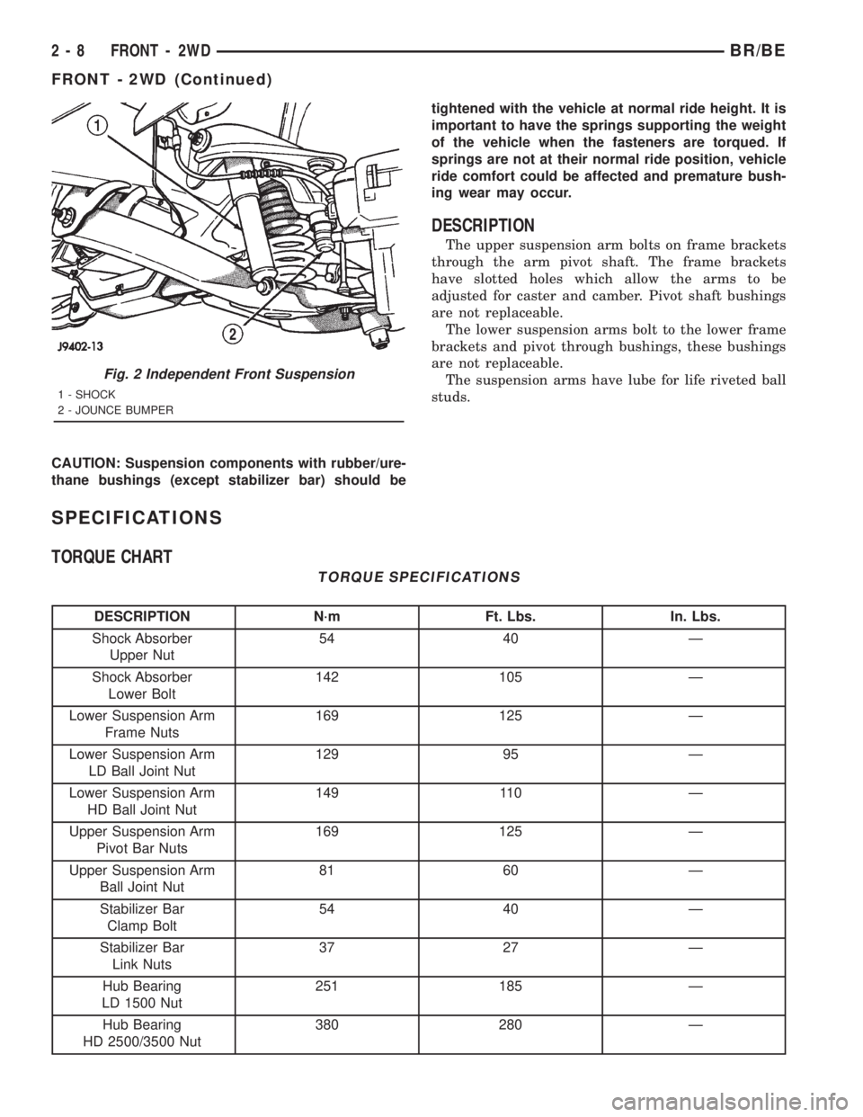
DESCRIPTION
The upper suspension arm bolts on frame brackets
through the arm pivot shaft. The frame brackets
have slotted holes which allow the arms to be
adjusted for caster and camber. Pivot shaft bushings
are not replaceable.
The lower suspension arms bolt to the lower frame
brackets and pivot through bushings, these bushings
are not replaceable.
The suspension arms have lube for life riveted ball
studs.
SPECIFICATIONS
TORQUE CHART
TORQUE SPECIFICATIONS
DESCRIPTION N´m Ft. Lbs. In. Lbs.
Shock Absorber
Upper Nut54 40 Ð
Shock Absorber
Lower Bolt142 105 Ð
Lower Suspension Arm
Frame Nuts169 125 Ð
Lower Suspension Arm
LD Ball Joint Nut129 95 Ð
Lower Suspension Arm
HD Ball Joint Nut149 110 Ð
Upper Suspension Arm
Pivot Bar Nuts169 125 Ð
Upper Suspension Arm
Ball Joint Nut81 60 Ð
Stabilizer Bar
Clamp Bolt54 40 Ð
Stabilizer Bar
Link Nuts37 27 Ð
Hub Bearing
LD 1500 Nut251 185 Ð
Hub Bearing
HD 2500/3500 Nut380 280 Ð
Fig. 2 Independent Front Suspension
1 - SHOCK
2 - JOUNCE BUMPER
2 - 8 FRONT - 2WDBR/BE
FRONT - 2WD (Continued)
Page 52 of 2889
SPECIAL TOOLS
INDEPENDENT FRONT SUSPENSION
HUB / BEARING
REMOVAL
(1) Raise and support the vehicle.
(2) Remove the wheel and tire assembly.
(3) Remove the caliper adapter bolts from the
steering knuckle and remove caliper adapter assem-
bly (Refer to 5 - BRAKES/HYDRAULIC/MECHANI-
CAL/DISC BRAKE CALIPERS - REMOVAL).
NOTE: Do not allow brake hose to support caliper
adapter assembly.
(4) Remove the rotor from the hub/bearing wheel
studs.
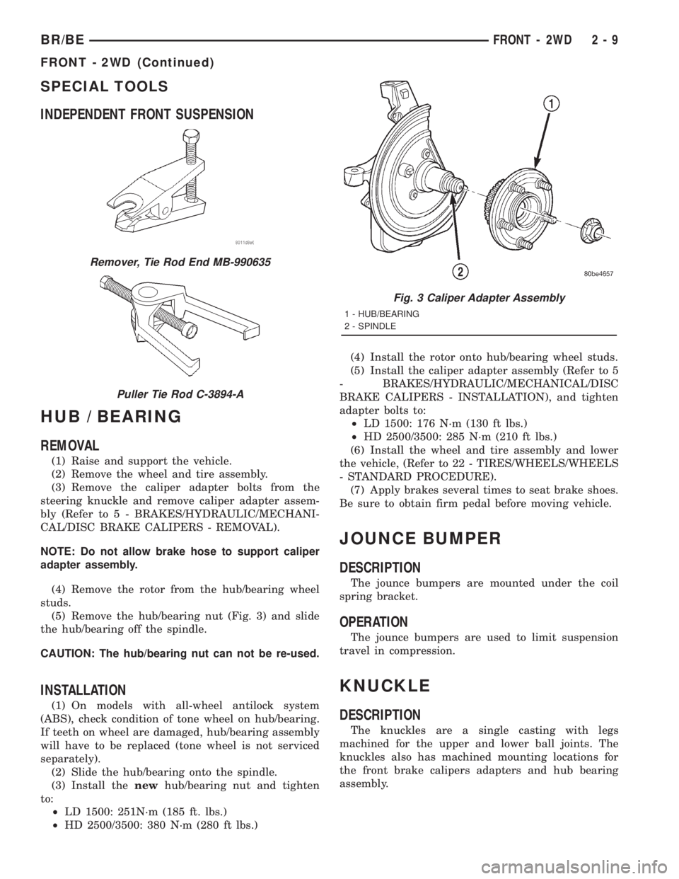
(5) Remove the hub/bearing nut (Fig. 3) and slide
the hub/bearing off the spindle.
CAUTION: The hub/bearing nut can not be re-used.
INSTALLATION
(1) On models with all-wheel antilock system
(ABS), check condition of tone wheel on hub/bearing.
If teeth on wheel are damaged, hub/bearing assembly
will have to be replaced (tone wheel is not serviced
separately).
(2) Slide the hub/bearing onto the spindle.
(3) Install thenewhub/bearing nut and tighten
to:
²LD 1500: 251N´m (185 ft. lbs.)
²HD 2500/3500: 380 N´m (280 ft lbs.)(4) Install the rotor onto hub/bearing wheel studs.
(5) Install the caliper adapter assembly (Refer to 5
- BRAKES/HYDRAULIC/MECHANICAL/DISC
BRAKE CALIPERS - INSTALLATION), and tighten
adapter bolts to:
²LD 1500: 176 N´m (130 ft lbs.)
²HD 2500/3500: 285 N´m (210 ft lbs.)
(6) Install the wheel and tire assembly and lower
the vehicle, (Refer to 22 - TIRES/WHEELS/WHEELS
- STANDARD PROCEDURE).
(7) Apply brakes several times to seat brake shoes.
Be sure to obtain firm pedal before moving vehicle.
JOUNCE BUMPER
DESCRIPTION
The jounce bumpers are mounted under the coil
spring bracket.
OPERATION
The jounce bumpers are used to limit suspension
travel in compression.
KNUCKLE
DESCRIPTION
The knuckles are a single casting with legs
machined for the upper and lower ball joints. The
knuckles also has machined mounting locations for
the front brake calipers adapters and hub bearing
assembly.
Remover, Tie Rod End MB-990635
Puller Tie Rod C-3894-A
Fig. 3 Caliper Adapter Assembly
1 - HUB/BEARING
2 - SPINDLE
BR/BEFRONT - 2WD 2 - 9
FRONT - 2WD (Continued)