2001 CHRYSLER VOYAGER fuse
[x] Cancel search: fusePage 4141 of 4284
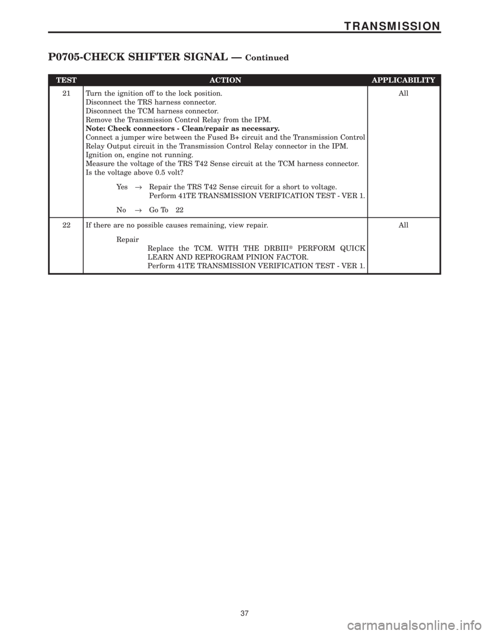
TEST ACTION APPLICABILITY
21 Turn the ignition off to the lock position.
Disconnect the TRS harness connector.
Disconnect the TCM harness connector.
Remove the Transmission Control Relay from the IPM.
Note: Check connectors - Clean/repair as necessary.
Connect a jumper wire between the Fused B+ circuit and the Transmission Control
Relay Output circuit in the Transmission Control Relay connector in the IPM.
Ignition on, engine not running.
Measure the voltage of the TRS T42 Sense circuit at the TCM harness connector.
Is the voltage above 0.5 volt?All
Ye s®Repair the TRS T42 Sense circuit for a short to voltage.
Perform 41TE TRANSMISSION VERIFICATION TEST - VER 1.
No®Go To 22
22 If there are no possible causes remaining, view repair. All
Repair
Replace the TCM. WITH THE DRBIIItPERFORM QUICK
LEARN AND REPROGRAM PINION FACTOR.
Perform 41TE TRANSMISSION VERIFICATION TEST - VER 1.
37
TRANSMISSION
P0705-CHECK SHIFTER SIGNAL ÐContinued
Page 4144 of 4284
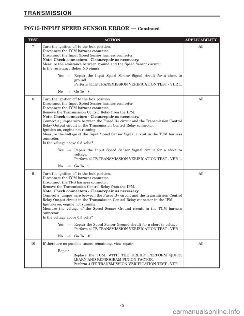
TEST ACTION APPLICABILITY
7 Turn the ignition off to the lock position.
Disconnect the TCM harness connector.
Disconnect the Input Speed Sensor harness connector.
Note: Check connectors - Clean/repair as necessary.
Measure the resistance between ground and the Speed Sensor circuit.
Is the resistance Below 5.0 ohms?All
Ye s®Repair the Input Speed Sensor Signal circuit for a short to
ground.
Perform 41TE TRANSMISSION VERIFICATION TEST - VER 1.
No®Go To 8
8 Turn the ignition off to the lock position.
Disconnect the Input Speed Sensor harness connector.
Disconnect the TCM harness connector.
Remove the Transmission Control Relay from the IPM.
Note: Check connectors - Clean/repair as necessary.
Connect a jumper wire between the Fused B+ circuit and the Transmission Control
Relay Output circuit in the Transmission Control Relay connector.
Ignition on, engine not running.
Measure the voltage of the Input Speed Sensor Signal circuit in the TCM harness
connector.
Is the voltage above 0.5 volts?All
Ye s®Repair the Input Speed Sensor Signal circuit for a short to
voltage.
Perform 41TE TRANSMISSION VERIFICATION TEST - VER 1.
No®Go To 9
9 Turn the ignition off to the lock position.
Disconnect the TCM harness connector.
Disconnect the TRS harness connector.
Remove the Transmission Control Relay from the IPM.
Note: Check connectors - Clean/repair as necessary.
Connect a jumper wire between the Fused B+ circuit and the Transmission Control
Relay Output circuit in the Transmission Control Relay connector in the IPM.
Ignition on, engine not running.
Measure the voltage of the Speed Sensor Ground circuit in the TCM harness
connector.
Is the voltage above 0.5 volts?All
Ye s®Repair the Speed Sensor Ground circuit for a short to voltage.
Perform 41TE TRANSMISSION VERIFICATION TEST - VER 1.
No®Go To 10
10 If there are no possible causes remaining, view repair. All
Repair
Replace the TCM. WITH THE DRBIIItPERFORM QUICK
LEARN AND REPROGRAM PINION FACTOR.
Perform 41TE TRANSMISSION VERIFICATION TEST - VER 1.
40
TRANSMISSION
P0715-INPUT SPEED SENSOR ERROR ÐContinued
Page 4148 of 4284
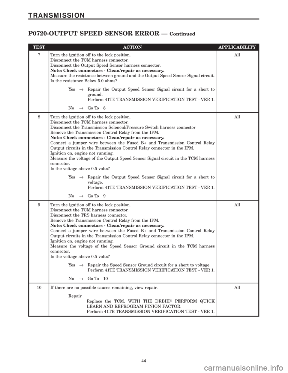
TEST ACTION APPLICABILITY
7 Turn the ignition off to the lock position.
Disconnect the TCM harness connector.
Disconnect the Output Speed Sensor harness connector.
Note: Check connectors - Clean/repair as necessary.
Measure the resistance between ground and the Output Speed Sensor Signal circuit.
Is the resistance Below 5.0 ohms?All
Ye s®Repair the Output Speed Sensor Signal circuit for a short to
ground.
Perform 41TE TRANSMISSION VERIFICATION TEST - VER 1.
No®Go To 8
8 Turn the ignition off to the lock position.
Disconnect the TCM harness connector.
Disconnect the Transmission Solenoid/Pressure Switch harness connector
Remove the Transmission Control Relay from the IPM.
Note: Check connectors - Clean/repair as necessary.
Connect a jumper wire between the Fused B+ and Transmission Control Relay
Output circuits in the Transmission Control Relay connector in the IPM.
Ignition on, engine not running.
Measure the voltage of the Output Speed Sensor Signal circuit in the TCM harness
connector.
Is the voltage above 0.5 volts?All
Ye s®Repair the Output Speed Sensor Signal circuit for a short to
voltage.
Perform 41TE TRANSMISSION VERIFICATION TEST - VER 1.
No®Go To 9
9 Turn the ignition off to the lock position.
Disconnect the TCM harness connector.
Disconnect the TRS harness connector.
Remove the Transmission Control Relay from the IPM.
Note: Check connectors - Clean/repair as necessary.
Connect a jumper wire between the Fused B+ and Transmission Control Relay
Output circuits in the Transmission Control Relay connector in the IPM.
Ignition on, engine not running.
Measure the voltage of the Speed Sensor Ground circuit in the TCM harness
connector.
Is the voltage above 0.5 volts?All
Ye s®Repair the Speed Sensor Ground circuit for a short to voltage.
Perform 41TE TRANSMISSION VERIFICATION TEST - VER 1.
No®Go To 10
10 If there are no possible causes remaining, view repair. All
Repair
Replace the TCM. WITH THE DRBIIItPERFORM QUICK
LEARN AND REPROGRAM PINION FACTOR.
Perform 41TE TRANSMISSION VERIFICATION TEST - VER 1.
44
TRANSMISSION
P0720-OUTPUT SPEED SENSOR ERROR ÐContinued
Page 4168 of 4284
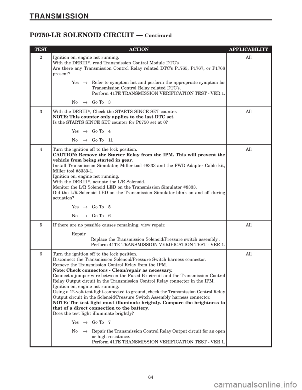
TEST ACTION APPLICABILITY
2 Ignition on, engine not running.
With the DRBIIIt, read Transmission Control Module DTC's
Are there any Transmission Control Relay related DTC's P1765, P1767, or P1768
present?All
Ye s®Refer to symptom list and perform the appropriate symptom for
Transmission Control Relay related DTC's.
Perform 41TE TRANSMISSION VERIFICATION TEST - VER 1.
No®Go To 3
3 With the DRBIIIt, Check the STARTS SINCE SET counter.
NOTE: This counter only applies to the last DTC set.
Is the STARTS SINCE SET counter for P0750 set at 0?All
Ye s®Go To 4
No®Go To 11
4 Turn the ignition off to the lock position.
CAUTION: Remove the Starter Relay from the IPM. This will prevent the
vehicle from being started in gear.
Install Transmission Simulator, Miller tool #8333 and the FWD Adapter Cable kit,
Miller tool #8333-1.
Ignition on, engine not running.
With the DRBIIIt, actuate the L/R Solenoid.
Monitor the L/R Solenoid LED on the Transmission Simulator #8333.
Did the L/R Solenoid LED on the Transmission Simulator blink on and off during
actuation?All
Ye s®Go To 5
No®Go To 6
5 If there are no possible causes remaining, view repair. All
Repair
Replace the Transmission Solenoid/Pressure switch assembly .
Perform 41TE TRANSMISSION VERIFICATION TEST - VER 1.
6 Turn the ignition off to the lock position.
Disconnect the Transmission Solenoid/Pressure Switch harness connector.
Remove the Transmission Control Relay from the IPM.
Note: Check connectors - Clean/repair as necessary.
Connect a jumper wire between the Fused B+ circuit and the Transmission Control
Relay Output circuit in the Transmission Control Relay connector in the IPM.
Ignition on, engine not running.
Using a 12-volt test light connected to ground, check the Transmission Control Relay
Output circuit in the Solenoid/Pressure Switch Assembly harness connector.
NOTE: The test light must illuminate brightly. Compare the brightness to
that of a direct connection to the battery.
Does the test light illuminate brightly?All
Ye s®Go To 7
No®Repair the Transmission Control Relay Output circuit for an open
or high resistance.
Perform 41TE TRANSMISSION VERIFICATION TEST - VER 1.
64
TRANSMISSION
P0750-LR SOLENOID CIRCUIT ÐContinued
Page 4169 of 4284
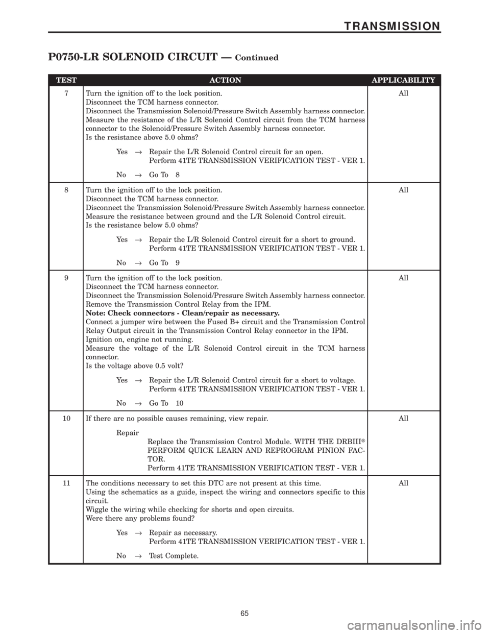
TEST ACTION APPLICABILITY
7 Turn the ignition off to the lock position.
Disconnect the TCM harness connector.
Disconnect the Transmission Solenoid/Pressure Switch Assembly harness connector.
Measure the resistance of the L/R Solenoid Control circuit from the TCM harness
connector to the Solenoid/Pressure Switch Assembly harness connector.
Is the resistance above 5.0 ohms?All
Ye s®Repair the L/R Solenoid Control circuit for an open.
Perform 41TE TRANSMISSION VERIFICATION TEST - VER 1.
No®Go To 8
8 Turn the ignition off to the lock position.
Disconnect the TCM harness connector.
Disconnect the Transmission Solenoid/Pressure Switch Assembly harness connector.
Measure the resistance between ground and the L/R Solenoid Control circuit.
Is the resistance below 5.0 ohms?All
Ye s®Repair the L/R Solenoid Control circuit for a short to ground.
Perform 41TE TRANSMISSION VERIFICATION TEST - VER 1.
No®Go To 9
9 Turn the ignition off to the lock position.
Disconnect the TCM harness connector.
Disconnect the Transmission Solenoid/Pressure Switch Assembly harness connector.
Remove the Transmission Control Relay from the IPM.
Note: Check connectors - Clean/repair as necessary.
Connect a jumper wire between the Fused B+ circuit and the Transmission Control
Relay Output circuit in the Transmission Control Relay connector in the IPM.
Ignition on, engine not running.
Measure the voltage of the L/R Solenoid Control circuit in the TCM harness
connector.
Is the voltage above 0.5 volt?All
Ye s®Repair the L/R Solenoid Control circuit for a short to voltage.
Perform 41TE TRANSMISSION VERIFICATION TEST - VER 1.
No®Go To 10
10 If there are no possible causes remaining, view repair. All
Repair
Replace the Transmission Control Module. WITH THE DRBIIIt
PERFORM QUICK LEARN AND REPROGRAM PINION FAC-
TOR.
Perform 41TE TRANSMISSION VERIFICATION TEST - VER 1.
11 The conditions necessary to set this DTC are not present at this time.
Using the schematics as a guide, inspect the wiring and connectors specific to this
circuit.
Wiggle the wiring while checking for shorts and open circuits.
Were there any problems found?All
Ye s®Repair as necessary.
Perform 41TE TRANSMISSION VERIFICATION TEST - VER 1.
No®Test Complete.
65
TRANSMISSION
P0750-LR SOLENOID CIRCUIT ÐContinued
Page 4171 of 4284
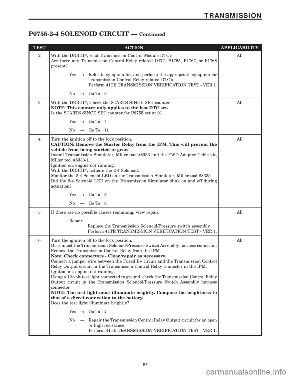
TEST ACTION APPLICABILITY
2 With the DRBIIIt, read Transmission Control Module DTC's
Are there any Transmission Control Relay related DTC's P1765, P1767, or P1768
present?.All
Ye s®Refer to symptom list and perform the appropriate symptom for
Transmission Control Relay related DTC's.
Perform 41TE TRANSMISSION VERIFICATION TEST - VER 1.
No®Go To 3
3 With the DRBIIIt, Check the STARTS SINCE SET counter.
NOTE: This counter only applies to the last DTC set.
Is the STARTS SINCE SET counter for P0755 set at 0?All
Ye s®Go To 4
No®Go To 11
4 Turn the ignition off to the lock position.
CAUTION: Remove the Starter Relay from the IPM. This will prevent the
vehicle from being started in gear.
Install Transmission Simulator, Miller tool #8333 and the FWD Adapter Cable kit,
Miller tool #8333-1.
Ignition on, engine not running.
With the DRBIIIt, actuate the 2-4 Solenoid.
Monitor the 2-4 Solenoid LED on the Transmission Simulator, Miller tool #8333
Did the 2-4 Solenoid LED on the Transmission Simulator blink on and off during
actuation?All
Ye s®Go To 5
No®Go To 6
5 If there are no possible causes remaining, view repair. All
Repair
Replace the Transmission Solenoid/Pressure switch assembly.
Perform 41TE TRANSMISSION VERIFICATION TEST - VER 1.
6 Turn the ignition off to the lock position.
Disconnect the Transmission Solenoid/Pressure Switch Assembly harness connector.
Remove the Transmission Control Relay from the IPM.
Note: Check connectors - Clean/repair as necessary.
Connect a jumper wire between the Fused B+ circuit and the Transmission Control
Relay Output circuit in the Transmission Control Relay connector in the IPM.
Ignition on, engine not running.
Using a 12-volt test light connected to ground, check the Transmission Control Relay
Output circuit in the Transmission Solenoid/Pressure Switch Assembly harness
connector.
NOTE: The test light must illuminate brightly. Compare the brightness to
that of a direct connection to the battery.
Does the test light illuminate brightly?All
Ye s®Go To 7
No®Repair the Transmission Control Relay Output circuit for an open
or high resistance.
Perform 41TE TRANSMISSION VERIFICATION TEST - VER 1.
67
TRANSMISSION
P0755-2-4 SOLENOID CIRCUIT ÐContinued
Page 4172 of 4284
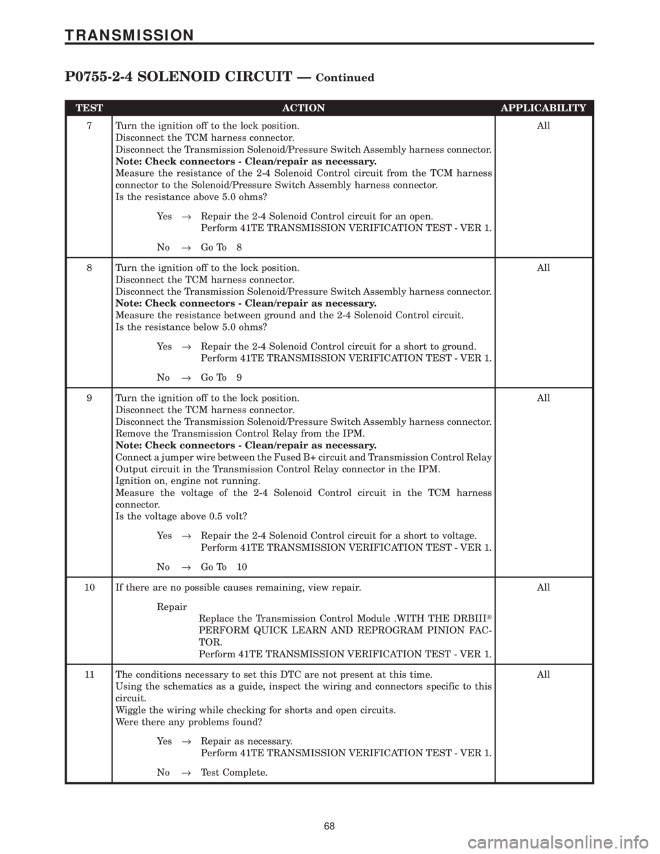
TEST ACTION APPLICABILITY
7 Turn the ignition off to the lock position.
Disconnect the TCM harness connector.
Disconnect the Transmission Solenoid/Pressure Switch Assembly harness connector.
Note: Check connectors - Clean/repair as necessary.
Measure the resistance of the 2-4 Solenoid Control circuit from the TCM harness
connector to the Solenoid/Pressure Switch Assembly harness connector.
Is the resistance above 5.0 ohms?All
Ye s®Repair the 2-4 Solenoid Control circuit for an open.
Perform 41TE TRANSMISSION VERIFICATION TEST - VER 1.
No®Go To 8
8 Turn the ignition off to the lock position.
Disconnect the TCM harness connector.
Disconnect the Transmission Solenoid/Pressure Switch Assembly harness connector.
Note: Check connectors - Clean/repair as necessary.
Measure the resistance between ground and the 2-4 Solenoid Control circuit.
Is the resistance below 5.0 ohms?All
Ye s®Repair the 2-4 Solenoid Control circuit for a short to ground.
Perform 41TE TRANSMISSION VERIFICATION TEST - VER 1.
No®Go To 9
9 Turn the ignition off to the lock position.
Disconnect the TCM harness connector.
Disconnect the Transmission Solenoid/Pressure Switch Assembly harness connector.
Remove the Transmission Control Relay from the IPM.
Note: Check connectors - Clean/repair as necessary.
Connect a jumper wire between the Fused B+ circuit and Transmission Control Relay
Output circuit in the Transmission Control Relay connector in the IPM.
Ignition on, engine not running.
Measure the voltage of the 2-4 Solenoid Control circuit in the TCM harness
connector.
Is the voltage above 0.5 volt?All
Ye s®Repair the 2-4 Solenoid Control circuit for a short to voltage.
Perform 41TE TRANSMISSION VERIFICATION TEST - VER 1.
No®Go To 10
10 If there are no possible causes remaining, view repair. All
Repair
Replace the Transmission Control Module .WITH THE DRBIIIt
PERFORM QUICK LEARN AND REPROGRAM PINION FAC-
TOR.
Perform 41TE TRANSMISSION VERIFICATION TEST - VER 1.
11 The conditions necessary to set this DTC are not present at this time.
Using the schematics as a guide, inspect the wiring and connectors specific to this
circuit.
Wiggle the wiring while checking for shorts and open circuits.
Were there any problems found?All
Ye s®Repair as necessary.
Perform 41TE TRANSMISSION VERIFICATION TEST - VER 1.
No®Test Complete.
68
TRANSMISSION
P0755-2-4 SOLENOID CIRCUIT ÐContinued
Page 4174 of 4284
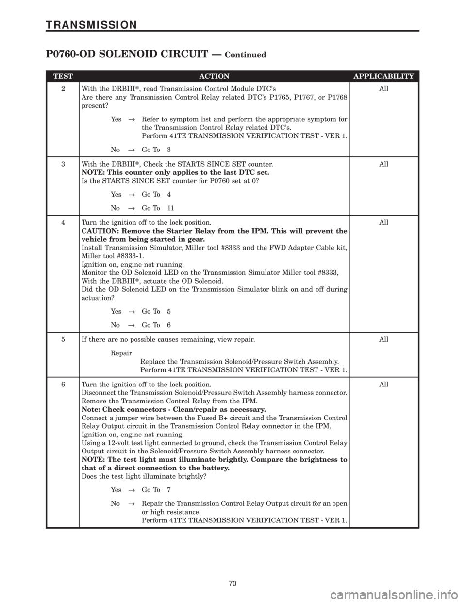
TEST ACTION APPLICABILITY
2 With the DRBIIIt, read Transmission Control Module DTC's
Are there any Transmission Control Relay related DTC's P1765, P1767, or P1768
present?All
Ye s®Refer to symptom list and perform the appropriate symptom for
the Transmission Control Relay related DTC's.
Perform 41TE TRANSMISSION VERIFICATION TEST - VER 1.
No®Go To 3
3 With the DRBIIIt, Check the STARTS SINCE SET counter.
NOTE: This counter only applies to the last DTC set.
Is the STARTS SINCE SET counter for P0760 set at 0?All
Ye s®Go To 4
No®Go To 11
4 Turn the ignition off to the lock position.
CAUTION: Remove the Starter Relay from the IPM. This will prevent the
vehicle from being started in gear.
Install Transmission Simulator, Miller tool #8333 and the FWD Adapter Cable kit,
Miller tool #8333-1.
Ignition on, engine not running.
Monitor the OD Solenoid LED on the Transmission Simulator Miller tool #8333,
With the DRBIIIt, actuate the OD Solenoid.
Did the OD Solenoid LED on the Transmission Simulator blink on and off during
actuation?All
Ye s®Go To 5
No®Go To 6
5 If there are no possible causes remaining, view repair. All
Repair
Replace the Transmission Solenoid/Pressure Switch Assembly.
Perform 41TE TRANSMISSION VERIFICATION TEST - VER 1.
6 Turn the ignition off to the lock position.
Disconnect the Transmission Solenoid/Pressure Switch Assembly harness connector.
Remove the Transmission Control Relay from the IPM.
Note: Check connectors - Clean/repair as necessary.
Connect a jumper wire between the Fused B+ circuit and the Transmission Control
Relay Output circuit in the Transmission Control Relay connector in the IPM.
Ignition on, engine not running.
Using a 12-volt test light connected to ground, check the Transmission Control Relay
Output circuit in the Solenoid/Pressure Switch Assembly harness connector.
NOTE: The test light must illuminate brightly. Compare the brightness to
that of a direct connection to the battery.
Does the test light illuminate brightly?All
Ye s®Go To 7
No®Repair the Transmission Control Relay Output circuit for an open
or high resistance.
Perform 41TE TRANSMISSION VERIFICATION TEST - VER 1.
70
TRANSMISSION
P0760-OD SOLENOID CIRCUIT ÐContinued