2001 CHRYSLER VOYAGER fuse
[x] Cancel search: fusePage 4224 of 4284
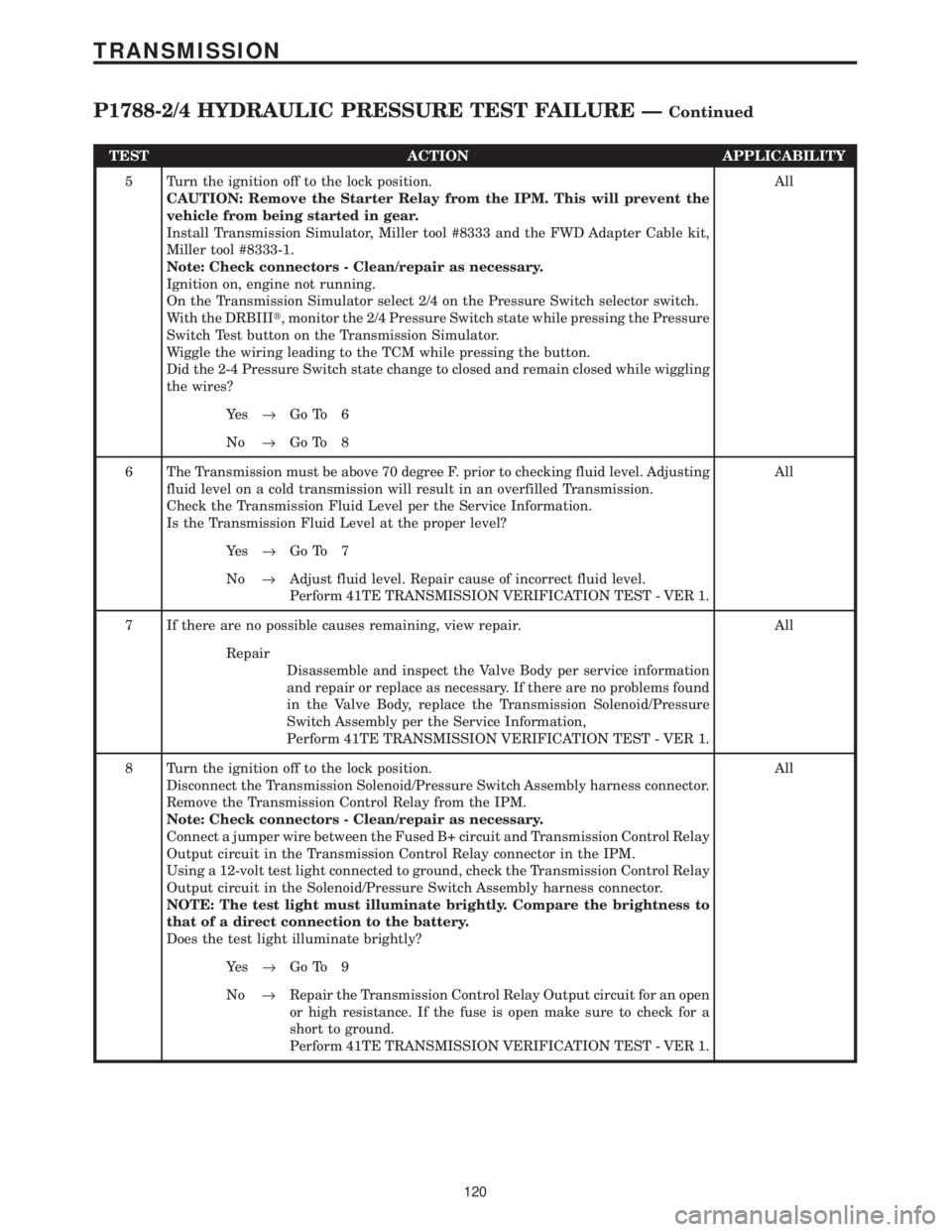
TEST ACTION APPLICABILITY
5 Turn the ignition off to the lock position.
CAUTION: Remove the Starter Relay from the IPM. This will prevent the
vehicle from being started in gear.
Install Transmission Simulator, Miller tool #8333 and the FWD Adapter Cable kit,
Miller tool #8333-1.
Note: Check connectors - Clean/repair as necessary.
Ignition on, engine not running.
On the Transmission Simulator select 2/4 on the Pressure Switch selector switch.
With the DRBIIIt, monitor the 2/4 Pressure Switch state while pressing the Pressure
Switch Test button on the Transmission Simulator.
Wiggle the wiring leading to the TCM while pressing the button.
Did the 2-4 Pressure Switch state change to closed and remain closed while wiggling
the wires?All
Ye s®Go To 6
No®Go To 8
6 The Transmission must be above 70 degree F. prior to checking fluid level. Adjusting
fluid level on a cold transmission will result in an overfilled Transmission.
Check the Transmission Fluid Level per the Service Information.
Is the Transmission Fluid Level at the proper level?All
Ye s®Go To 7
No®Adjust fluid level. Repair cause of incorrect fluid level.
Perform 41TE TRANSMISSION VERIFICATION TEST - VER 1.
7 If there are no possible causes remaining, view repair. All
Repair
Disassemble and inspect the Valve Body per service information
and repair or replace as necessary. If there are no problems found
in the Valve Body, replace the Transmission Solenoid/Pressure
Switch Assembly per the Service Information,
Perform 41TE TRANSMISSION VERIFICATION TEST - VER 1.
8 Turn the ignition off to the lock position.
Disconnect the Transmission Solenoid/Pressure Switch Assembly harness connector.
Remove the Transmission Control Relay from the IPM.
Note: Check connectors - Clean/repair as necessary.
Connect a jumper wire between the Fused B+ circuit and Transmission Control Relay
Output circuit in the Transmission Control Relay connector in the IPM.
Using a 12-volt test light connected to ground, check the Transmission Control Relay
Output circuit in the Solenoid/Pressure Switch Assembly harness connector.
NOTE: The test light must illuminate brightly. Compare the brightness to
that of a direct connection to the battery.
Does the test light illuminate brightly?All
Ye s®Go To 9
No®Repair the Transmission Control Relay Output circuit for an open
or high resistance. If the fuse is open make sure to check for a
short to ground.
Perform 41TE TRANSMISSION VERIFICATION TEST - VER 1.
120
TRANSMISSION
P1788-2/4 HYDRAULIC PRESSURE TEST FAILURE ÐContinued
Page 4225 of 4284
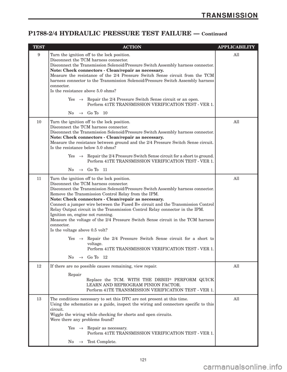
TEST ACTION APPLICABILITY
9 Turn the ignition off to the lock position.
Disconnect the TCM harness connector.
Disconnect the Transmission Solenoid/Pressure Switch Assembly harness connector.
Note: Check connectors - Clean/repair as necessary.
Measure the resistance of the 2/4 Pressure Switch Sense circuit from the TCM
harness connector to the Transmission Solenoid/Pressure Switch Assembly harness
connector.
Is the resistance above 5.0 ohms?All
Ye s®Repair the 2/4 Pressure Switch Sense circuit or an open.
Perform 41TE TRANSMISSION VERIFICATION TEST - VER 1.
No®Go To 10
10 Turn the ignition off to the lock position.
Disconnect the TCM harness connector.
Disconnect the Transmission Solenoid/Pressure Switch Assembly harness connector.
Note: Check connectors - Clean/repair as necessary.
Measure the resistance between ground and the 2/4 Pressure Switch Sense circuit.
Is the resistance below 5.0 ohms?All
Ye s®Repair the 2/4 Pressure Switch Sense circuit for a short to ground.
Perform 41TE TRANSMISSION VERIFICATION TEST - VER 1.
No®Go To 11
11 Turn the ignition off to the lock position.
Disconnect the TCM harness connector.
Disconnect the Transmission Solenoid/Pressure Switch Assembly harness connector.
Remove the Transmission Control Relay from the IPM.
Note: Check connectors - Clean/repair as necessary.
Connect a jumper wire between the Fused B+ circuit and the Transmission Control
Relay Output circuit in the Transmission Control Relay connector in the IPM.
Ignition on, engine not running.
Measure the voltage of the 2/4 Pressure Switch Sense circuit in the TCM harness
connector.
Is the voltage above 0.5 volt?All
Ye s®Repair the 2/4 Pressure Switch Sense circuit for a short to
voltage.
Perform 41TE TRANSMISSION VERIFICATION TEST - VER 1.
No®Go To 12
12 If there are no possible causes remaining, view repair. All
Repair
Replace the TCM. WITH THE DRBIIItPERFORM QUICK
LEARN AND REPROGRAM PINION FACTOR.
Perform 41TE TRANSMISSION VERIFICATION TEST - VER 1.
13 The conditions necessary to set this DTC are not present at this time.
Using the schematics as a guide, inspect the wiring and connectors specific to this
circuit.
Wiggle the wiring while checking for shorts and open circuits.
Were there any problems found?All
Ye s®Repair as necessary.
Perform 41TE TRANSMISSION VERIFICATION TEST - VER 1.
No®Test Complete.
121
TRANSMISSION
P1788-2/4 HYDRAULIC PRESSURE TEST FAILURE ÐContinued
Page 4231 of 4284
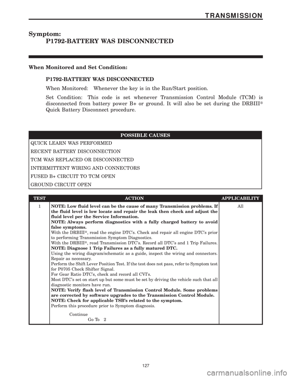
Symptom:
P1792-BATTERY WAS DISCONNECTED
When Monitored and Set Condition:
P1792-BATTERY WAS DISCONNECTED
When Monitored: Whenever the key is in the Run/Start position.
Set Condition: This code is set whenever Transmission Control Module (TCM) is
disconnected from battery power B+ or ground. It will also be set during the DRBIIIt
Quick Battery Disconnect procedure.
POSSIBLE CAUSES
QUICK LEARN WAS PERFORMED
RECENT BATTERY DISCONNECTION
TCM WAS REPLACED OR DISCONNECTED
INTERMITTENT WIRING AND CONNECTORS
FUSED B+ CIRCUIT TO TCM OPEN
GROUND CIRCUIT OPEN
TEST ACTION APPLICABILITY
1NOTE: Low fluid level can be the cause of many Transmission problems. If
the fluid level is low locate and repair the leak then check and adjust the
fluid level per the Service Information.
NOTE: Always perform diagnostics with a fully charged battery to avoid
false symptoms.
With the DRBIIIt, read the engine DTC's. Check and repair all engine DTC's prior
to performing Transmission Symptom Diagnostics.
With the DRBIIIt, read Transmission DTC's. Record all DTC's and 1 Trip Failures.
NOTE: Diagnose 1 Trip Failures as a fully matured DTC.
Using the wiring diagram/schematic as a guide, inspect the wiring and connectors.
Repair as necessary.
Perform the Shift Lever Position Test. If the test does not pass, refer to Symptom test
for P0705 Check Shifter Signal.
For Gear Ratio DTC's, check and record all CVI's.
Most DTC's set on start up but some must be set by driving the vehicle such that all
diagnostic monitors have run.
NOTE: Verify flash level of Transmission Control Module. Some problems
are corrected by software upgrades to the Transmission Control Module.
NOTE: Check for applicable TSB's related to the symptom.
Perform this procedure prior to Symptom diagnosis.All
Continue
Go To 2
127
TRANSMISSION
Page 4232 of 4284
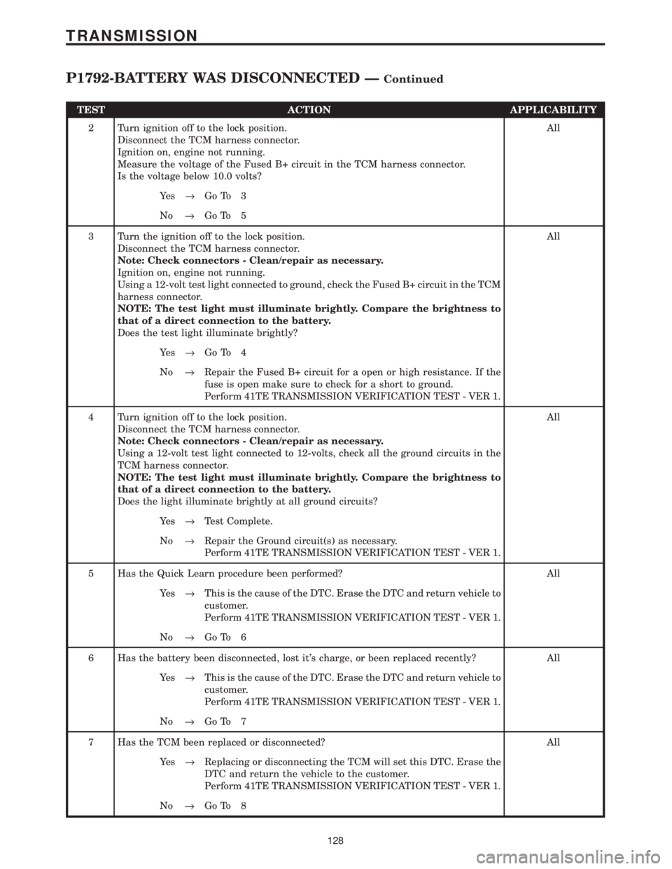
TEST ACTION APPLICABILITY
2 Turn ignition off to the lock position.
Disconnect the TCM harness connector.
Ignition on, engine not running.
Measure the voltage of the Fused B+ circuit in the TCM harness connector.
Is the voltage below 10.0 volts?All
Ye s®Go To 3
No®Go To 5
3 Turn the ignition off to the lock position.
Disconnect the TCM harness connector.
Note: Check connectors - Clean/repair as necessary.
Ignition on, engine not running.
Using a 12-volt test light connected to ground, check the Fused B+ circuit in the TCM
harness connector.
NOTE: The test light must illuminate brightly. Compare the brightness to
that of a direct connection to the battery.
Does the test light illuminate brightly?All
Ye s®Go To 4
No®Repair the Fused B+ circuit for a open or high resistance. If the
fuse is open make sure to check for a short to ground.
Perform 41TE TRANSMISSION VERIFICATION TEST - VER 1.
4 Turn ignition off to the lock position.
Disconnect the TCM harness connector.
Note: Check connectors - Clean/repair as necessary.
Using a 12-volt test light connected to 12-volts, check all the ground circuits in the
TCM harness connector.
NOTE: The test light must illuminate brightly. Compare the brightness to
that of a direct connection to the battery.
Does the light illuminate brightly at all ground circuits?All
Ye s®Test Complete.
No®Repair the Ground circuit(s) as necessary.
Perform 41TE TRANSMISSION VERIFICATION TEST - VER 1.
5 Has the Quick Learn procedure been performed? All
Ye s®This is the cause of the DTC. Erase the DTC and return vehicle to
customer.
Perform 41TE TRANSMISSION VERIFICATION TEST - VER 1.
No®Go To 6
6 Has the battery been disconnected, lost it's charge, or been replaced recently? All
Ye s®This is the cause of the DTC. Erase the DTC and return vehicle to
customer.
Perform 41TE TRANSMISSION VERIFICATION TEST - VER 1.
No®Go To 7
7 Has the TCM been replaced or disconnected? All
Ye s®Replacing or disconnecting the TCM will set this DTC. Erase the
DTC and return the vehicle to the customer.
Perform 41TE TRANSMISSION VERIFICATION TEST - VER 1.
No®Go To 8
128
TRANSMISSION
P1792-BATTERY WAS DISCONNECTED ÐContinued
Page 4248 of 4284
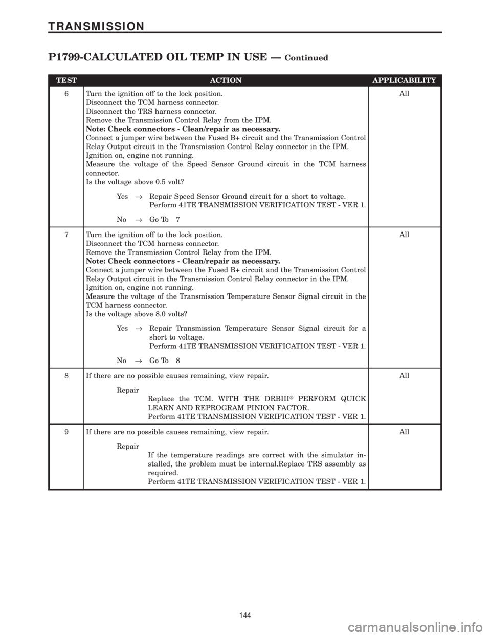
TEST ACTION APPLICABILITY
6 Turn the ignition off to the lock position.
Disconnect the TCM harness connector.
Disconnect the TRS harness connector.
Remove the Transmission Control Relay from the IPM.
Note: Check connectors - Clean/repair as necessary.
Connect a jumper wire between the Fused B+ circuit and the Transmission Control
Relay Output circuit in the Transmission Control Relay connector in the IPM.
Ignition on, engine not running.
Measure the voltage of the Speed Sensor Ground circuit in the TCM harness
connector.
Is the voltage above 0.5 volt?All
Ye s®Repair Speed Sensor Ground circuit for a short to voltage.
Perform 41TE TRANSMISSION VERIFICATION TEST - VER 1.
No®Go To 7
7 Turn the ignition off to the lock position.
Disconnect the TCM harness connector.
Remove the Transmission Control Relay from the IPM.
Note: Check connectors - Clean/repair as necessary.
Connect a jumper wire between the Fused B+ circuit and the Transmission Control
Relay Output circuit in the Transmission Control Relay connector in the IPM.
Ignition on, engine not running.
Measure the voltage of the Transmission Temperature Sensor Signal circuit in the
TCM harness connector.
Is the voltage above 8.0 volts?All
Ye s®Repair Transmission Temperature Sensor Signal circuit for a
short to voltage.
Perform 41TE TRANSMISSION VERIFICATION TEST - VER 1.
No®Go To 8
8 If there are no possible causes remaining, view repair. All
Repair
Replace the TCM. WITH THE DRBIIItPERFORM QUICK
LEARN AND REPROGRAM PINION FACTOR.
Perform 41TE TRANSMISSION VERIFICATION TEST - VER 1.
9 If there are no possible causes remaining, view repair. All
Repair
If the temperature readings are correct with the simulator in-
stalled, the problem must be internal.Replace TRS assembly as
required.
Perform 41TE TRANSMISSION VERIFICATION TEST - VER 1.
144
TRANSMISSION
P1799-CALCULATED OIL TEMP IN USE ÐContinued
Page 4267 of 4284
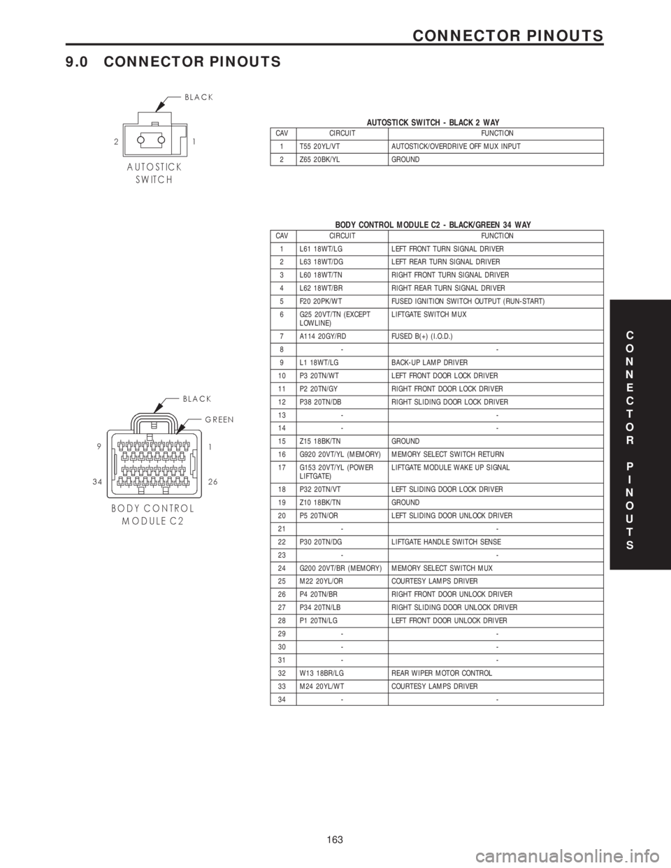
9.0 CONNECTOR PINOUTS
AUTOSTICK SWITCH - BLACK 2 WAYCAV CIRCUIT FUNCTION
1 T55 20YL/VT AUTOSTICK/OVERDRIVE OFF MUX INPUT
2 Z65 20BK/YL GROUND
BODY CONTROL MODULE C2 - BLACK/GREEN 34 WAYCAV CIRCUIT FUNCTION
1 L61 18WT/LG LEFT FRONT TURN SIGNAL DRIVER
2 L63 18WT/DG LEFT REAR TURN SIGNAL DRIVER
3 L60 18WT/TN RIGHT FRONT TURN SIGNAL DRIVER
4 L62 18WT/BR RIGHT REAR TURN SIGNAL DRIVER
5 F20 20PK/WT FUSED IGNITION SWITCH OUTPUT (RUN-START)
6 G25 20VT/TN (EXCEPT
LOWLINE)LIFTGATE SWITCH MUX
7 A114 20GY/RD FUSED B(+) (I.O.D.)
8- -
9 L1 18WT/LG BACK-UP LAMP DRIVER
10 P3 20TN/WT LEFT FRONT DOOR LOCK DRIVER
11 P2 20TN/GY RIGHT FRONT DOOR LOCK DRIVER
12 P38 20TN/DB RIGHT SLIDING DOOR LOCK DRIVER
13 - -
14 - -
15 Z15 18BK/TN GROUND
16 G920 20VT/YL (MEMORY) MEMORY SELECT SWITCH RETURN
17 G153 20VT/YL (POWER
LIFTGATE)LIFTGATE MODULE WAKE UP SIGNAL
18 P32 20TN/VT LEFT SLIDING DOOR LOCK DRIVER
19 Z10 18BK/TN GROUND
20 P5 20TN/OR LEFT SLIDING DOOR UNLOCK DRIVER
21 - -
22 P30 20TN/DG LIFTGATE HANDLE SWITCH SENSE
23 - -
24 G200 20VT/BR (MEMORY) MEMORY SELECT SWITCH MUX
25 M22 20YL/OR COURTESY LAMPS DRIVER
26 P4 20TN/BR RIGHT FRONT DOOR UNLOCK DRIVER
27 P34 20TN/LB RIGHT SLIDING DOOR UNLOCK DRIVER
28 P1 20TN/LG LEFT FRONT DOOR UNLOCK DRIVER
29 - -
30 - -
31 - -
32 W13 18BR/LG REAR WIPER MOTOR CONTROL
33 M24 20YL/WT COURTESY LAMPS DRIVER
34 - -
C
O
N
N
E
C
T
O
R
P
I
N
O
U
T
S
163
CONNECTOR PINOUTS
Page 4268 of 4284

BRAKE LAMP SWITCH - BLACK 6 WAYCAV CIRCUIT FUNCTION
1 A103 18GY/RD FUSED B(+)
2 L50 18WT/TN BRAKE LAMP SWITCH OUTPUT
3 V30 20VT/WT SPEED CONTROL BRAKE SWITCH OUTPUT
4 V32 20VT/YL SPEED CONTROL ON/OFF SWITCH SENSE
5 Z429 20BK/OR GROUND
6 B29 20DG/WT BRAKE SWITCH SENSE
CRANKSHAFT POSITION SENSOR - BLACK 3 WAYCAV CIRCUIT FUNCTION
1 F888 18BR/PK 8 VOLT SUPPLY
2 K900 18DB/DG SENSOR GROUND
3 K24 18BR/LB CRANKSHAFT POSITION SENSOR SIGNAL
DATA LINK CONNECTOR - WHITE 16 WAYCAV CIRCUIT FUNCTION
1- -
2 D25 20WT/VT PCI BUS
3- -
4 Z11 18BK/LG GROUND
5 Z111 18BK/WT GROUND
6 D20 20WT/LG SCI RECEIVE
7 D21 20WT/BR SCI TRANSMIT
8- -
9 D23 20WT/BR FLASH PROGRAM ENABLE
10 - -
11 - -
12 - -
13 - -
14 D16 20WT/OR SCI RECEIVE
15 - -
16 A105 20DB/RD FUSED B(+)
C
O
N
N
E
C
T
O
R
P
I
N
O
U
T
S
164
CONNECTOR PINOUTS
Page 4269 of 4284
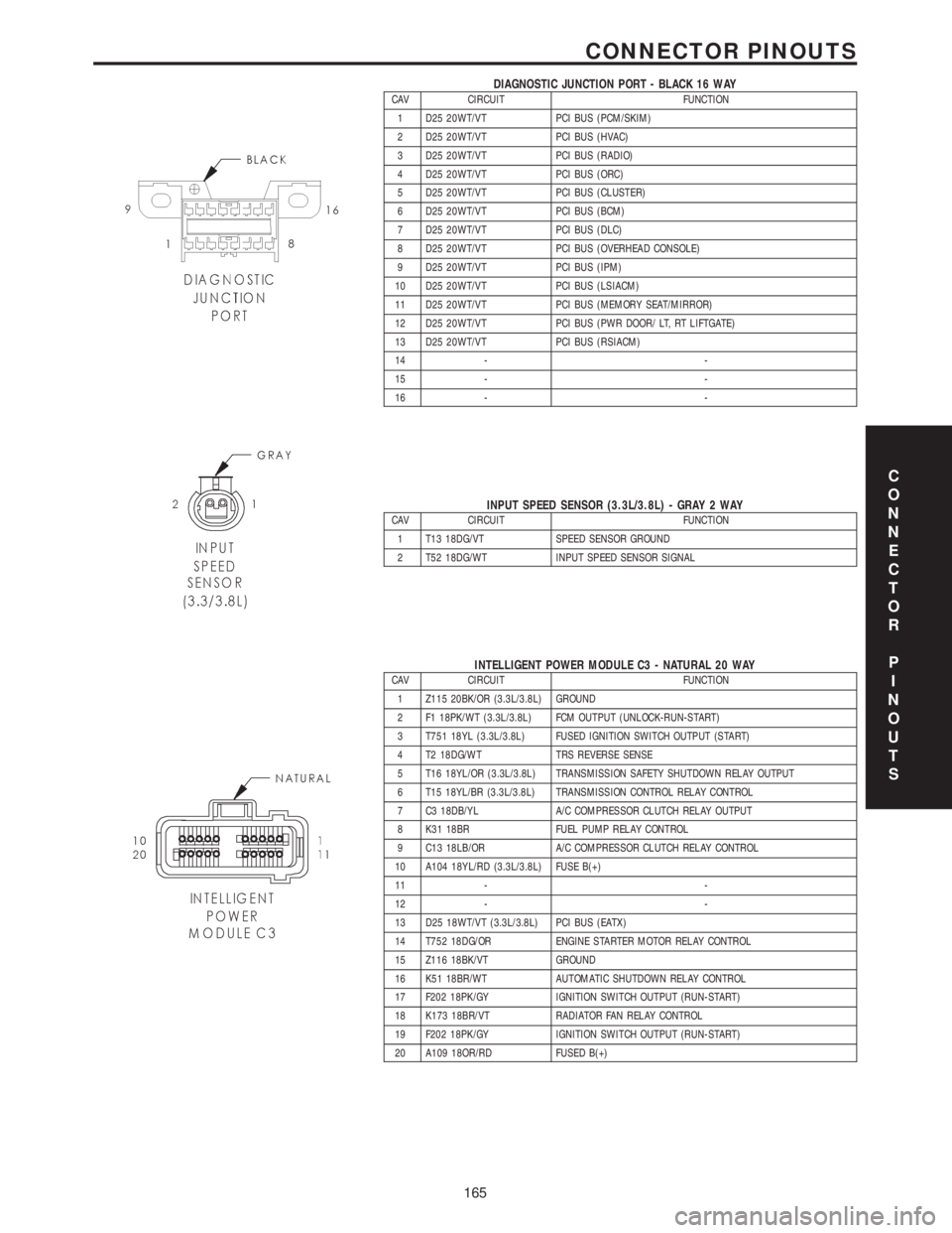
DIAGNOSTIC JUNCTION PORT - BLACK 16 WAYCAV CIRCUIT FUNCTION
1 D25 20WT/VT PCI BUS (PCM/SKIM)
2 D25 20WT/VT PCI BUS (HVAC)
3 D25 20WT/VT PCI BUS (RADIO)
4 D25 20WT/VT PCI BUS (ORC)
5 D25 20WT/VT PCI BUS (CLUSTER)
6 D25 20WT/VT PCI BUS (BCM)
7 D25 20WT/VT PCI BUS (DLC)
8 D25 20WT/VT PCI BUS (OVERHEAD CONSOLE)
9 D25 20WT/VT PCI BUS (IPM)
10 D25 20WT/VT PCI BUS (LSIACM)
11 D25 20WT/VT PCI BUS (MEMORY SEAT/MIRROR)
12 D25 20WT/VT PCI BUS (PWR DOOR/ LT, RT LIFTGATE)
13 D25 20WT/VT PCI BUS (RSIACM)
14 - -
15 - -
16 - -
INPUT SPEED SENSOR (3.3L/3.8L) - GRAY 2 WAYCAV CIRCUIT FUNCTION
1 T13 18DG/VT SPEED SENSOR GROUND
2 T52 18DG/WT INPUT SPEED SENSOR SIGNAL
INTELLIGENT POWER MODULE C3 - NATURAL 20 WAYCAV CIRCUIT FUNCTION
1 Z115 20BK/OR (3.3L/3.8L) GROUND
2 F1 18PK/WT (3.3L/3.8L) FCM OUTPUT (UNLOCK-RUN-START)
3 T751 18YL (3.3L/3.8L) FUSED IGNITION SWITCH OUTPUT (START)
4 T2 18DG/WT TRS REVERSE SENSE
5 T16 18YL/OR (3.3L/3.8L) TRANSMISSION SAFETY SHUTDOWN RELAY OUTPUT
6 T15 18YL/BR (3.3L/3.8L) TRANSMISSION CONTROL RELAY CONTROL
7 C3 18DB/YL A/C COMPRESSOR CLUTCH RELAY OUTPUT
8 K31 18BR FUEL PUMP RELAY CONTROL
9 C13 18LB/OR A/C COMPRESSOR CLUTCH RELAY CONTROL
10 A104 18YL/RD (3.3L/3.8L) FUSE B(+)
11 - -
12 - -
13 D25 18WT/VT (3.3L/3.8L) PCI BUS (EATX)
14 T752 18DG/OR ENGINE STARTER MOTOR RELAY CONTROL
15 Z116 18BK/VT GROUND
16 K51 18BR/WT AUTOMATIC SHUTDOWN RELAY CONTROL
17 F202 18PK/GY IGNITION SWITCH OUTPUT (RUN-START)
18 K173 18BR/VT RADIATOR FAN RELAY CONTROL
19 F202 18PK/GY IGNITION SWITCH OUTPUT (RUN-START)
20 A109 18OR/RD FUSED B(+)
C
O
N
N
E
C
T
O
R
P
I
N
O
U
T
S
165
CONNECTOR PINOUTS