2001 CHRYSLER VOYAGER fuse
[x] Cancel search: fusePage 3918 of 4284
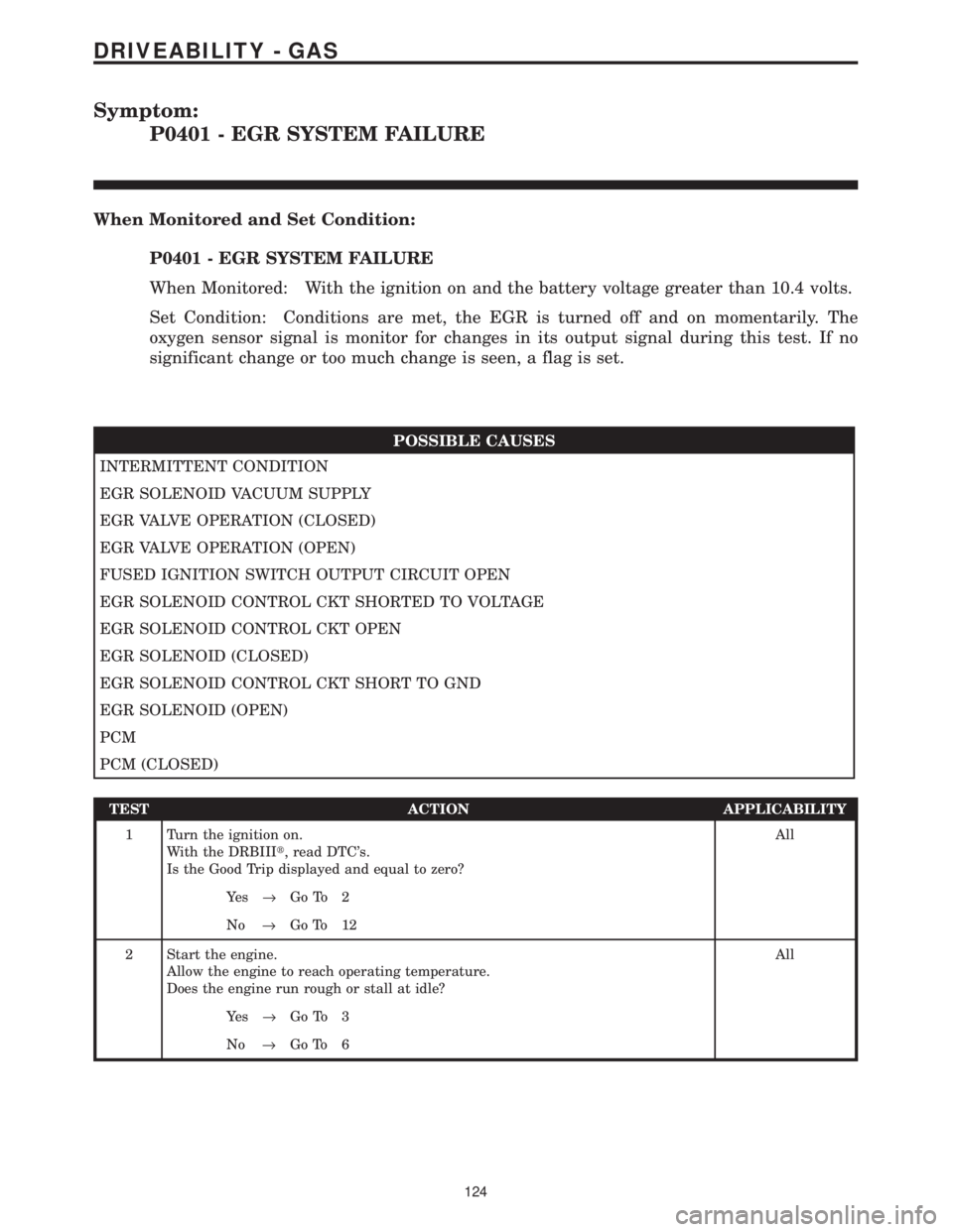
Symptom:
P0401 - EGR SYSTEM FAILURE
When Monitored and Set Condition:
P0401 - EGR SYSTEM FAILURE
When Monitored: With the ignition on and the battery voltage greater than 10.4 volts.
Set Condition: Conditions are met, the EGR is turned off and on momentarily. The
oxygen sensor signal is monitor for changes in its output signal during this test. If no
significant change or too much change is seen, a flag is set.
POSSIBLE CAUSES
INTERMITTENT CONDITION
EGR SOLENOID VACUUM SUPPLY
EGR VALVE OPERATION (CLOSED)
EGR VALVE OPERATION (OPEN)
FUSED IGNITION SWITCH OUTPUT CIRCUIT OPEN
EGR SOLENOID CONTROL CKT SHORTED TO VOLTAGE
EGR SOLENOID CONTROL CKT OPEN
EGR SOLENOID (CLOSED)
EGR SOLENOID CONTROL CKT SHORT TO GND
EGR SOLENOID (OPEN)
PCM
PCM (CLOSED)
TEST ACTION APPLICABILITY
1 Turn the ignition on.
With the DRBIIIt, read DTC's.
Is the Good Trip displayed and equal to zero?All
Ye s®Go To 2
No®Go To 12
2 Start the engine.
Allow the engine to reach operating temperature.
Does the engine run rough or stall at idle?All
Ye s®Go To 3
No®Go To 6
124
DRIVEABILITY - GAS
Page 3920 of 4284
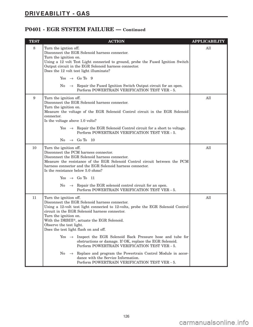
TEST ACTION APPLICABILITY
8 Turn the igntion off.
Disconnect the EGR Solenoid harness connector.
Turn the ignition on.
Using a 12 volt Test Light connected to ground, probe the Fused Ignition Switch
Output circuit in the EGR Solenoid harness connector.
Does the 12 volt test light illuminate?All
Ye s®Go To 9
No®Repair the Fused Ignition Switch Output circuit for an open.
Perform POWERTRAIN VERIFICATION TEST VER - 5.
9 Turn the ignition off.
Disconnect the EGR Solenoid harness connector.
Turn the ignition on.
Measure the voltage of the EGR Solenoid Control circuit in the EGR Solenoid
connector.
Is the voltage above 1.0 volts?All
Ye s®Repair the EGR Solenoid Control circuit for a short to voltage.
Perform POWERTRAIN VERIFICATION TEST VER - 5.
No®Go To 10
10 Turn the ignition off.
Disconnect the PCM harness connector.
Disconnect the EGR Solenoid harness connector.
Measure the resistance of the EGR Solenoid Control circuit between the PCM
harness connector and the EGR Solenoid harness connector.
Is the resistance below 5.0 ohms?All
Ye s®Go To 11
No®Repair the EGR solenoid control circuit for an open.
Perform POWERTRAIN VERIFICATION TEST VER - 5.
11 Turn the ignition off.
Disconnect the EGR Solenoid harness connector.
Using a 12-volt test light connected to 12-volts, probe the EGR Solenoid Control
circuit in the EGR Solenoid harness connector.
Turn the ignition on.
With the DRBIIIt, actuate the EGR Solenoid.
Observe the test light.
Does the test light flash on and off.All
Ye s®Inspect the EGR Solenoid Back Pressure hose and tube for
obstructions or damage. If OK, replace the EGR Solenoid.
Perform POWERTRAIN VERIFICATION TEST VER - 5.
No®Replace and program the Powertrain Control Module in accor-
dance with the Service Information.
Perform POWERTRAIN VERIFICATION TEST VER - 5.
126
DRIVEABILITY - GAS
P0401 - EGR SYSTEM FAILURE ÐContinued
Page 3922 of 4284
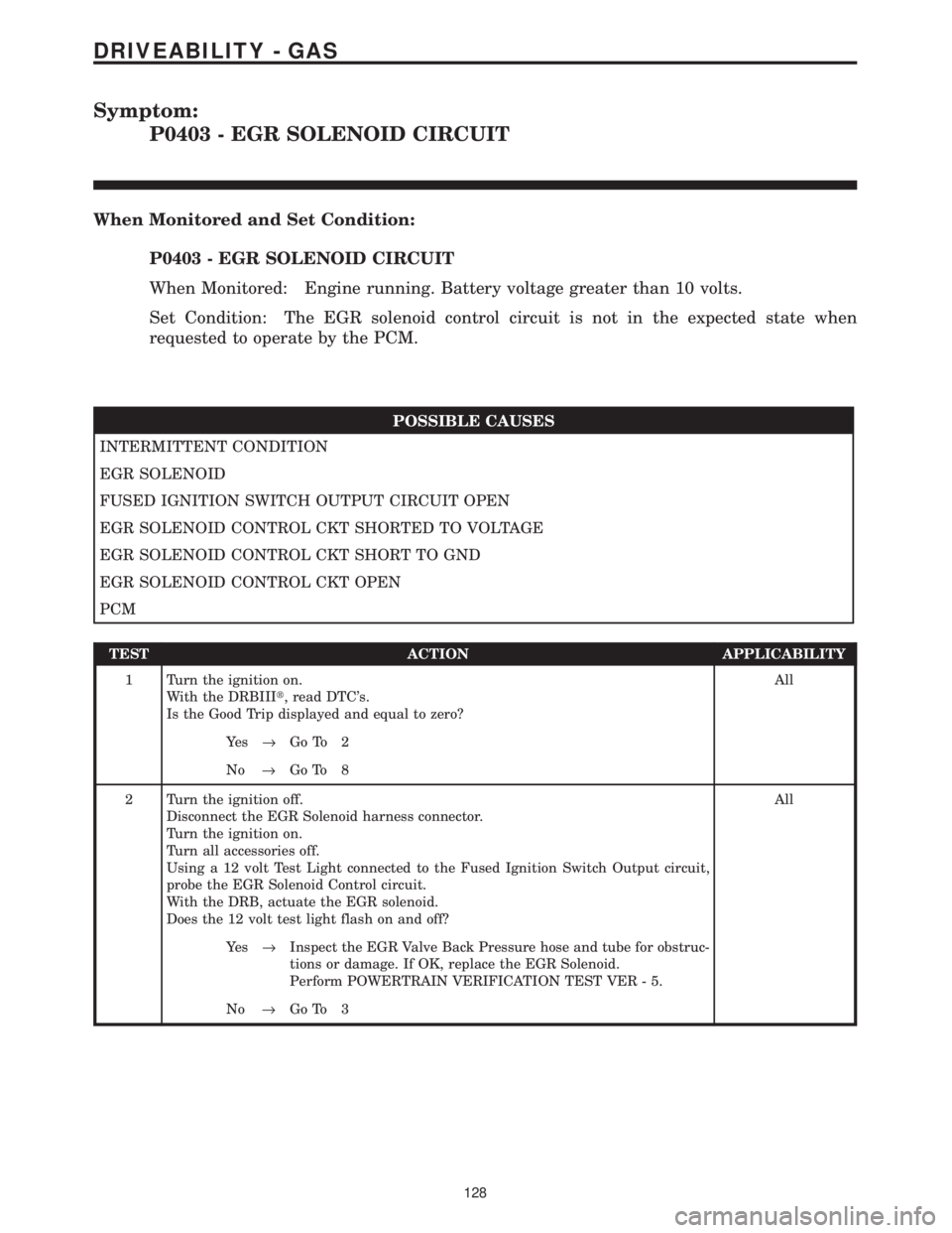
Symptom:
P0403 - EGR SOLENOID CIRCUIT
When Monitored and Set Condition:
P0403 - EGR SOLENOID CIRCUIT
When Monitored: Engine running. Battery voltage greater than 10 volts.
Set Condition: The EGR solenoid control circuit is not in the expected state when
requested to operate by the PCM.
POSSIBLE CAUSES
INTERMITTENT CONDITION
EGR SOLENOID
FUSED IGNITION SWITCH OUTPUT CIRCUIT OPEN
EGR SOLENOID CONTROL CKT SHORTED TO VOLTAGE
EGR SOLENOID CONTROL CKT SHORT TO GND
EGR SOLENOID CONTROL CKT OPEN
PCM
TEST ACTION APPLICABILITY
1 Turn the ignition on.
With the DRBIIIt, read DTC's.
Is the Good Trip displayed and equal to zero?All
Ye s®Go To 2
No®Go To 8
2 Turn the ignition off.
Disconnect the EGR Solenoid harness connector.
Turn the ignition on.
Turn all accessories off.
Using a 12 volt Test Light connected to the Fused Ignition Switch Output circuit,
probe the EGR Solenoid Control circuit.
With the DRB, actuate the EGR solenoid.
Does the 12 volt test light flash on and off?All
Ye s®Inspect the EGR Valve Back Pressure hose and tube for obstruc-
tions or damage. If OK, replace the EGR Solenoid.
Perform POWERTRAIN VERIFICATION TEST VER - 5.
No®Go To 3
128
DRIVEABILITY - GAS
Page 3923 of 4284
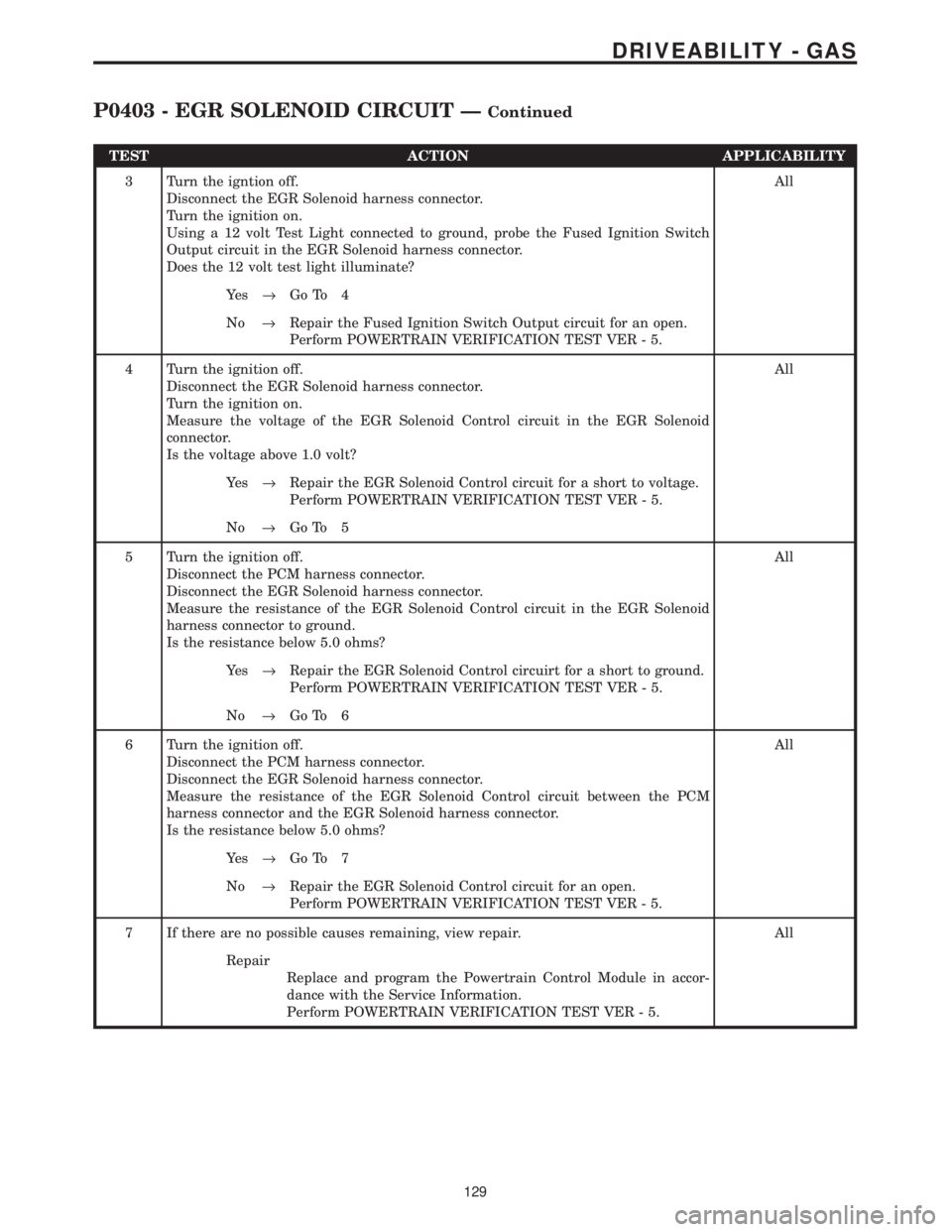
TEST ACTION APPLICABILITY
3 Turn the igntion off.
Disconnect the EGR Solenoid harness connector.
Turn the ignition on.
Using a 12 volt Test Light connected to ground, probe the Fused Ignition Switch
Output circuit in the EGR Solenoid harness connector.
Does the 12 volt test light illuminate?All
Ye s®Go To 4
No®Repair the Fused Ignition Switch Output circuit for an open.
Perform POWERTRAIN VERIFICATION TEST VER - 5.
4 Turn the ignition off.
Disconnect the EGR Solenoid harness connector.
Turn the ignition on.
Measure the voltage of the EGR Solenoid Control circuit in the EGR Solenoid
connector.
Is the voltage above 1.0 volt?All
Ye s®Repair the EGR Solenoid Control circuit for a short to voltage.
Perform POWERTRAIN VERIFICATION TEST VER - 5.
No®Go To 5
5 Turn the ignition off.
Disconnect the PCM harness connector.
Disconnect the EGR Solenoid harness connector.
Measure the resistance of the EGR Solenoid Control circuit in the EGR Solenoid
harness connector to ground.
Is the resistance below 5.0 ohms?All
Ye s®Repair the EGR Solenoid Control circuirt for a short to ground.
Perform POWERTRAIN VERIFICATION TEST VER - 5.
No®Go To 6
6 Turn the ignition off.
Disconnect the PCM harness connector.
Disconnect the EGR Solenoid harness connector.
Measure the resistance of the EGR Solenoid Control circuit between the PCM
harness connector and the EGR Solenoid harness connector.
Is the resistance below 5.0 ohms?All
Ye s®Go To 7
No®Repair the EGR Solenoid Control circuit for an open.
Perform POWERTRAIN VERIFICATION TEST VER - 5.
7 If there are no possible causes remaining, view repair. All
Repair
Replace and program the Powertrain Control Module in accor-
dance with the Service Information.
Perform POWERTRAIN VERIFICATION TEST VER - 5.
129
DRIVEABILITY - GAS
P0403 - EGR SOLENOID CIRCUIT ÐContinued
Page 3948 of 4284
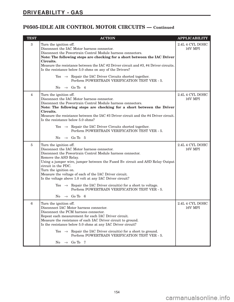
TEST ACTION APPLICABILITY
3 Turn the ignition off.
Disconnect the IAC Motor harness connector.
Disconnect the Powertrain Control Module harness connectors.
Note: The following steps are checking for a short between the IAC Driver
Circuits.
Measure the resistance between the IAC #2 Driver circuit and #3, #4 Driver circuits.
Is the resistance below 5.0 ohms on any of the Drivers?2.4L 4 CYL DOHC
16V MPI
Ye s®Repair the IAC Driver Circuits shorted together.
Perform POWERTRAIN VERIFICATION TEST VER - 5.
No®Go To 4
4 Turn the ignition off.
Disconnect the IAC Motor harness connector.
Disconnect the Powertrain Control Module harness connectors.
Note: The following steps are checking for a short between the Driver
Circuits.
Measure the resistance between the IAC #3 Driver circuit and the #4 Driver circuit.
Is the resistance below 5.0 ohms?2.4L 4 CYL DOHC
16V MPI
Ye s®Repair the IAC Driver Circuits shorted together.
Perform POWERTRAIN VERIFICATION TEST VER - 5.
No®Go To 5
5 Turn the ignition off.
Disconnect the IAC Motor harness connector.
Disconnect the Powertrain Control Module harness connector.
Remove the ASD Relay.
Using a jumper wire, jumper between the Fused B+ circuit and ASD Relay Output
circuit in the PDC.
Turn the ignition on.
Measure the voltage of each of the IAC Driver circuit.
Is the voltage above 1.0 volt at any IAC Driver circuit?2.4L 4 CYL DOHC
16V MPI
Ye s®Repair the IAC Driver circuit(s) for a short to voltage.
Perform POWERTRAIN VERIFICATION TEST VER - 5.
No®Go To 6
6 Turn the ignition off.
Disconnect IAC Motor harness connector.
Disconnect the PCM harness connector.
Repeat each measurement for each IAC Driver circuit.
Measure the resistance of each IAC Driver circuit to ground.
Is the resistance below 5.0 ohms at any IAC Driver circuit?2.4L 4 CYL DOHC
16V MPI
Ye s®Repair the IAC Driver circuit(s) for a short to ground.
Perform POWERTRAIN VERIFICATION TEST VER - 5.
No®Go To 7
154
DRIVEABILITY - GAS
P0505-IDLE AIR CONTROL MOTOR CIRCUITS ÐContinued
Page 3956 of 4284
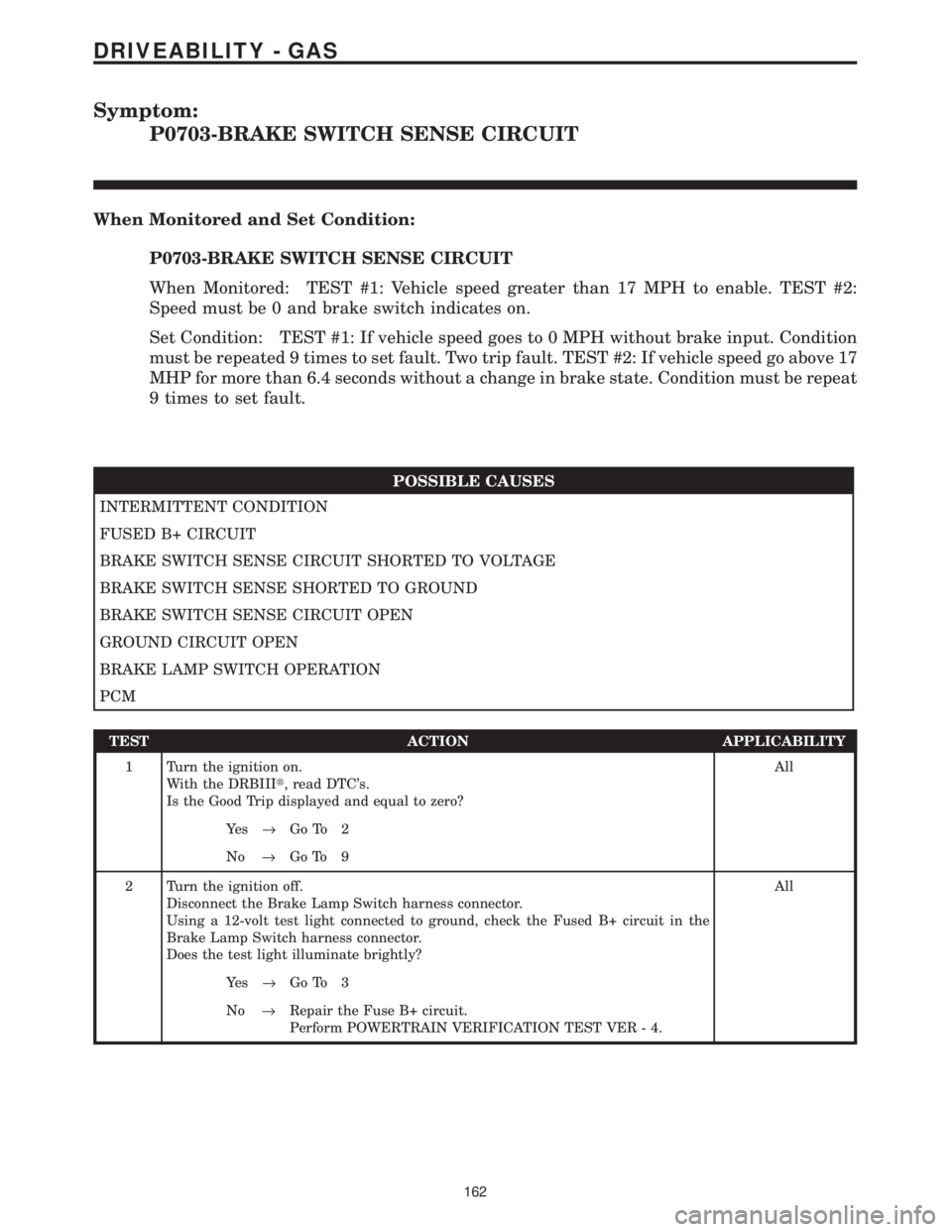
Symptom:
P0703-BRAKE SWITCH SENSE CIRCUIT
When Monitored and Set Condition:
P0703-BRAKE SWITCH SENSE CIRCUIT
When Monitored: TEST #1: Vehicle speed greater than 17 MPH to enable. TEST #2:
Speed must be 0 and brake switch indicates on.
Set Condition: TEST #1: If vehicle speed goes to 0 MPH without brake input. Condition
must be repeated 9 times to set fault. Two trip fault. TEST #2: If vehicle speed go above 17
MHP for more than 6.4 seconds without a change in brake state. Condition must be repeat
9 times to set fault.
POSSIBLE CAUSES
INTERMITTENT CONDITION
FUSED B+ CIRCUIT
BRAKE SWITCH SENSE CIRCUIT SHORTED TO VOLTAGE
BRAKE SWITCH SENSE SHORTED TO GROUND
BRAKE SWITCH SENSE CIRCUIT OPEN
GROUND CIRCUIT OPEN
BRAKE LAMP SWITCH OPERATION
PCM
TEST ACTION APPLICABILITY
1 Turn the ignition on.
With the DRBIIIt, read DTC's.
Is the Good Trip displayed and equal to zero?All
Ye s®Go To 2
No®Go To 9
2 Turn the ignition off.
Disconnect the Brake Lamp Switch harness connector.
Using a 12-volt test light connected to ground, check the Fused B+ circuit in the
Brake Lamp Switch harness connector.
Does the test light illuminate brightly?All
Ye s®Go To 3
No®Repair the Fuse B+ circuit.
Perform POWERTRAIN VERIFICATION TEST VER - 4.
162
DRIVEABILITY - GAS
Page 3957 of 4284
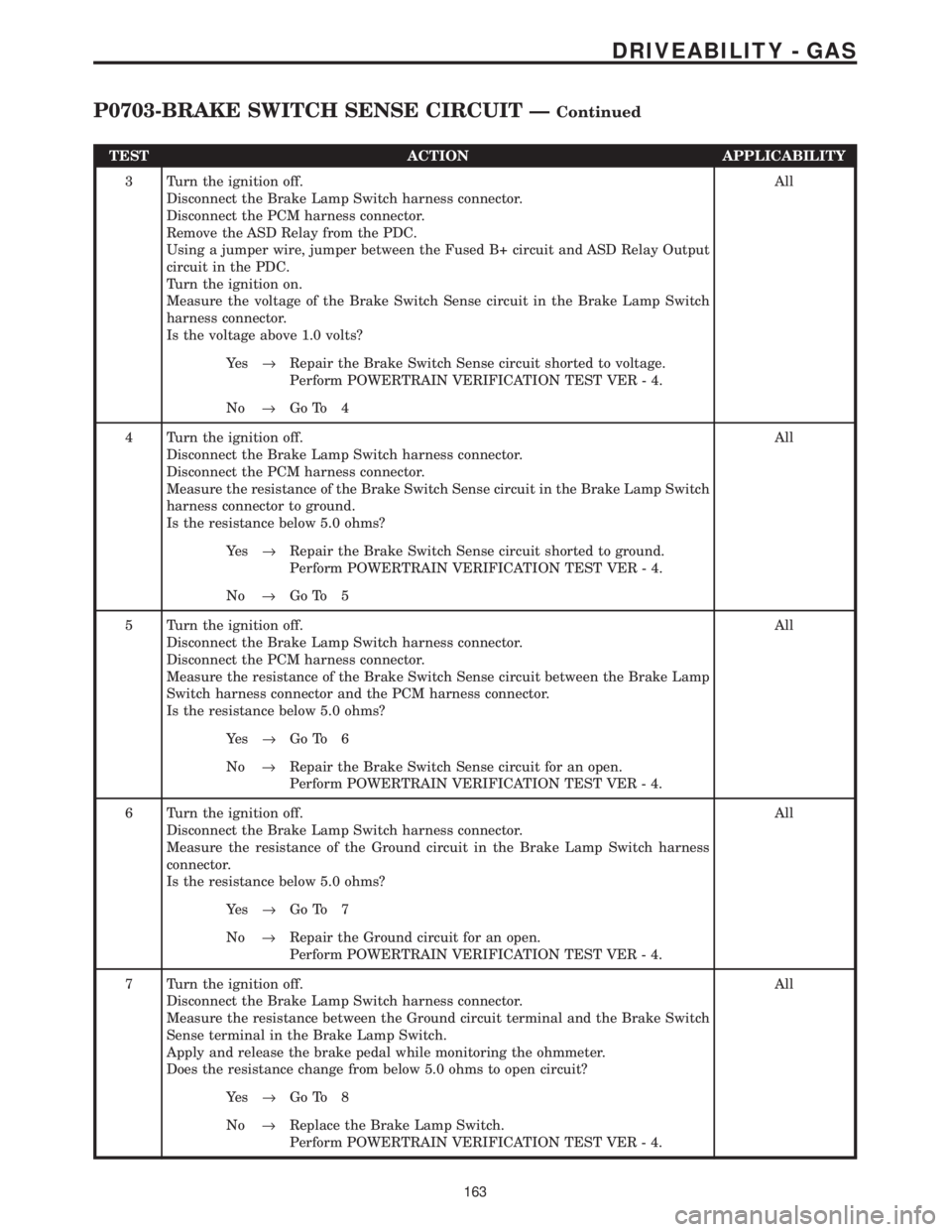
TEST ACTION APPLICABILITY
3 Turn the ignition off.
Disconnect the Brake Lamp Switch harness connector.
Disconnect the PCM harness connector.
Remove the ASD Relay from the PDC.
Using a jumper wire, jumper between the Fused B+ circuit and ASD Relay Output
circuit in the PDC.
Turn the ignition on.
Measure the voltage of the Brake Switch Sense circuit in the Brake Lamp Switch
harness connector.
Is the voltage above 1.0 volts?All
Ye s®Repair the Brake Switch Sense circuit shorted to voltage.
Perform POWERTRAIN VERIFICATION TEST VER - 4.
No®Go To 4
4 Turn the ignition off.
Disconnect the Brake Lamp Switch harness connector.
Disconnect the PCM harness connector.
Measure the resistance of the Brake Switch Sense circuit in the Brake Lamp Switch
harness connector to ground.
Is the resistance below 5.0 ohms?All
Ye s®Repair the Brake Switch Sense circuit shorted to ground.
Perform POWERTRAIN VERIFICATION TEST VER - 4.
No®Go To 5
5 Turn the ignition off.
Disconnect the Brake Lamp Switch harness connector.
Disconnect the PCM harness connector.
Measure the resistance of the Brake Switch Sense circuit between the Brake Lamp
Switch harness connector and the PCM harness connector.
Is the resistance below 5.0 ohms?All
Ye s®Go To 6
No®Repair the Brake Switch Sense circuit for an open.
Perform POWERTRAIN VERIFICATION TEST VER - 4.
6 Turn the ignition off.
Disconnect the Brake Lamp Switch harness connector.
Measure the resistance of the Ground circuit in the Brake Lamp Switch harness
connector.
Is the resistance below 5.0 ohms?All
Ye s®Go To 7
No®Repair the Ground circuit for an open.
Perform POWERTRAIN VERIFICATION TEST VER - 4.
7 Turn the ignition off.
Disconnect the Brake Lamp Switch harness connector.
Measure the resistance between the Ground circuit terminal and the Brake Switch
Sense terminal in the Brake Lamp Switch.
Apply and release the brake pedal while monitoring the ohmmeter.
Does the resistance change from below 5.0 ohms to open circuit?All
Ye s®Go To 8
No®Replace the Brake Lamp Switch.
Perform POWERTRAIN VERIFICATION TEST VER - 4.
163
DRIVEABILITY - GAS
P0703-BRAKE SWITCH SENSE CIRCUIT ÐContinued
Page 3959 of 4284
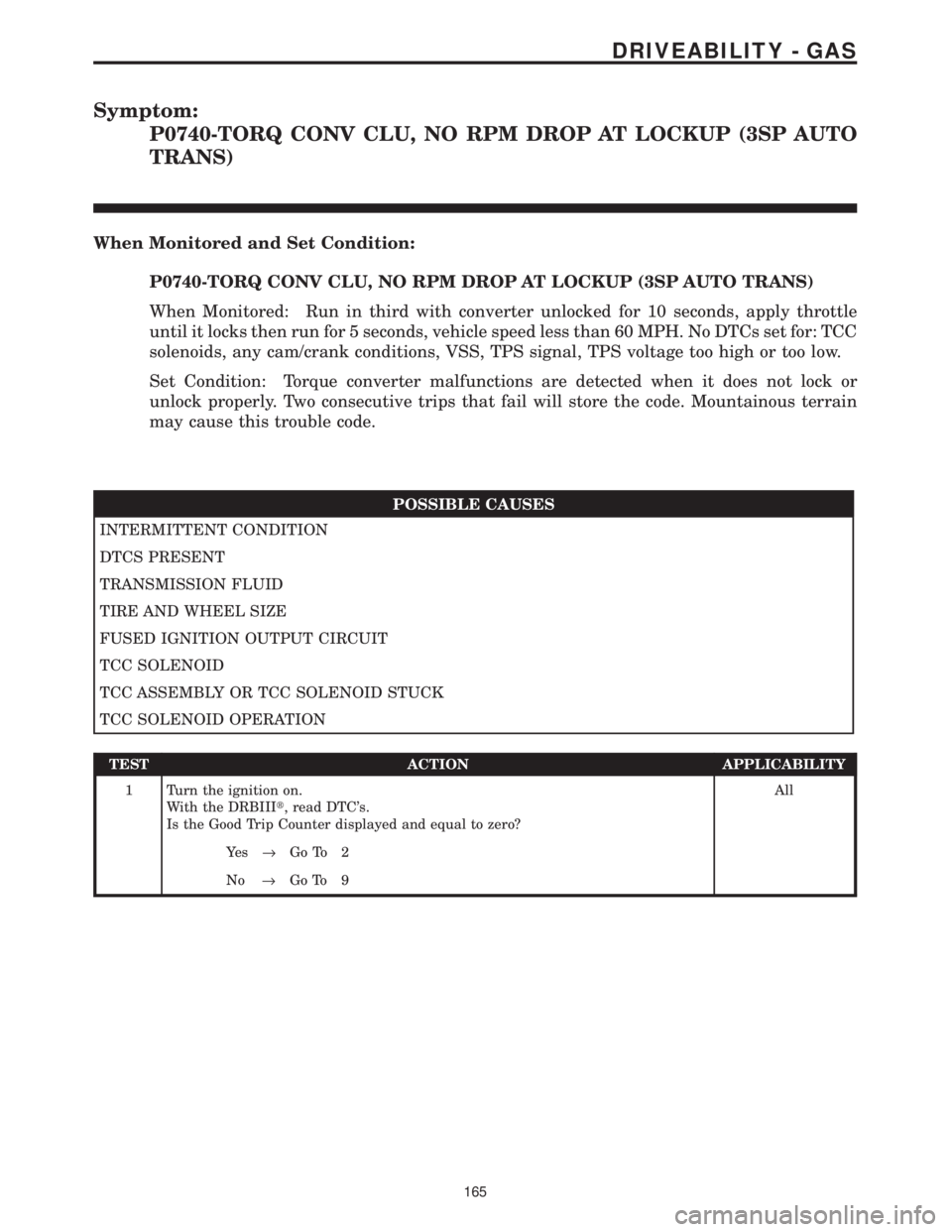
Symptom:
P0740-TORQ CONV CLU, NO RPM DROP AT LOCKUP (3SP AUTO
TRANS)
When Monitored and Set Condition:
P0740-TORQ CONV CLU, NO RPM DROP AT LOCKUP (3SP AUTO TRANS)
When Monitored: Run in third with converter unlocked for 10 seconds, apply throttle
until it locks then run for 5 seconds, vehicle speed less than 60 MPH. No DTCs set for: TCC
solenoids, any cam/crank conditions, VSS, TPS signal, TPS voltage too high or too low.
Set Condition: Torque converter malfunctions are detected when it does not lock or
unlock properly. Two consecutive trips that fail will store the code. Mountainous terrain
may cause this trouble code.
POSSIBLE CAUSES
INTERMITTENT CONDITION
DTCS PRESENT
TRANSMISSION FLUID
TIRE AND WHEEL SIZE
FUSED IGNITION OUTPUT CIRCUIT
TCC SOLENOID
TCC ASSEMBLY OR TCC SOLENOID STUCK
TCC SOLENOID OPERATION
TEST ACTION APPLICABILITY
1 Turn the ignition on.
With the DRBIIIt, read DTC's.
Is the Good Trip Counter displayed and equal to zero?All
Ye s®Go To 2
No®Go To 9
165
DRIVEABILITY - GAS