2001 CHRYSLER VOYAGER fuse
[x] Cancel search: fusePage 2559 of 4284
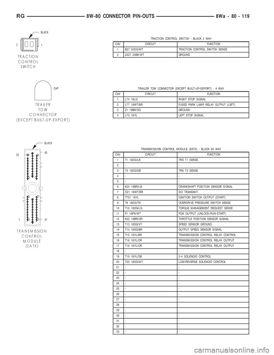
TRACTION CONTROL SWITCH - BLACK 2 WAY
CAV CIRCUIT FUNCTION
1 B27 20DG/WT TRACTION CONTROL SWITCH SENSE
2 Z427 20BK/WT GROUND
TRAILER TOW CONNECTOR (EXCEPT BUILT-UP-EXPORT)-4WAY
CAV CIRCUIT FUNCTION
1 L74 18LG RIGHT STOP SIGNAL
2 L77 18WT/BR FUSED PARK LAMP RELAY OUTPUT (LEFT)
3 Z1 18BK/DG GROUND
4 L73 18YL LEFT STOP SIGNAL
TRANSMISSION CONTROL MODULE (EATX) - BLACK 60 WAY
CAV CIRCUIT FUNCTION
1 T1 18DG/LB TRS T1 SENSE
2- -
3 T3 18DG/DB TRS T3 SENSE
4- -
5- -
6 K24 18BR/LB CRANKSHAFT POSITION SENSOR SIGNAL
7 D21 18WT/BR SCI TRANSMIT
8 T751 18YL IGNITION SWITCH OUTPUT (START)
9 T9 18DG/TN OVERDRIVE PRESSURE SWITCH SENSE
10 T10 18DG/LG TORQUE MANAGEMENT REQUEST SENSE
11 F1 18PK/WT FCM OUTPUT (UNLOCK-RUN-START)
12 K22 18BR/OR THROTTLE POSITION SENSOR SIGNAL
13 T13 18DG/VT SPEED SENSOR GROUND
14 T14 18DG/BR OUTPUT SPEED SENSOR SIGNAL
15 T15 18YL/BR TRANSMISSION CONTROL RELAY CONTROL
16 T16 18YL/OR TRANSMISSION CONTROL RELAY OUTPUT
17 T16 18YL/OR TRANSMISSION CONTROL RELAY OUTPUT
18 - -
19 T19 18YL/DB 2-4 SOLENOID CONTROL
20 T20 18DG/WT LOW/REVERSE SOLENOID CONTROL
21 - -
22 - -
23 - -
24 - -
25 - -
26 - -
27 - -
28 - -
29 - -
30 - -
31 - -
32 - -
33 - -
RG8W-80 CONNECTOR PIN-OUTS8Wa - 80 - 119
Page 2560 of 4284
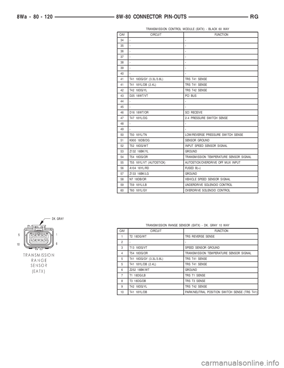
TRANSMISSION CONTROL MODULE (EATX) - BLACK 60 WAY
CAV CIRCUIT FUNCTION
34 - -
35 - -
36 - -
37 - -
38 - -
39 - -
40 - -
41 T41 18DG/GY (3.3L/3.8L) TRS T41 SENSE
41 T41 18YL/DB (2.4L) TRS T41 SENSE
42 T42 18DG/YL TRS T42 SENSE
43 D25 18WT/VT PCI BUS
44 - -
45 - -
46 D16 18WT/OR SCI RECEIVE
47 T47 18YL/DG 2-4 PRESSURE SWITCH SENSE
48 - -
49 - -
50 T50 18YL/TN LOW/REVERSE PRESSURE SWITCH SENSE
51 K900 18DB/DG SENSOR GROUND
52 T52 18DG/WT INPUT SPEED SENSOR SIGNAL
53 Z132 16BK/YL GROUND
54 T54 18DG/OR TRANSMISSION TEMPERATURE SENSOR SIGNAL
55 T55 18YL/VT (AUTOSTICK) AUTOSTICK/OVERDRIVE OFF MUX INPUT
56 A104 18YL/RD FUSED B(+)
57 Z133 16BK/LG GROUND
58 N7 18DB/OR VEHICLE SPEED SENSOR SIGNAL
59 T59 18YL/LB UNDERDRIVE SOLENOID CONTROL
60 T60 18YL/GY OVERDRIVE SOLENOID CONTROL
TRANSMISSION RANGE SENSOR (EATX) - DK. GRAY 10 WAY
CAV CIRCUIT FUNCTION
1 T2 18DG/WT TRS REVERSE SENSE
2- -
3 T13 18DG/VT SPEED SENSOR GROUND
4 T54 18DG/OR TRANSMISSION TEMPERATURE SENSOR SIGNAL
5 T41 18DG/GY (3.3L/3.8L) TRS T41 SENSE
5 T41 18YL/DB (2.4L) TRS T41 SENSE
6 Z252 18BK/WT GROUND
7 T1 18DG/LB TRS T1 SENSE
8 T3 18DG/DB TRS T3 SENSE
9 T42 18DG/YL TRS T42 SENSE
10 T41 18YL/DB PARK/NEUTRAL POSITION SWITCH SENSE (TRS T41)
8Wa - 80 - 120 8W-80 CONNECTOR PIN-OUTSRG
Page 2561 of 4284
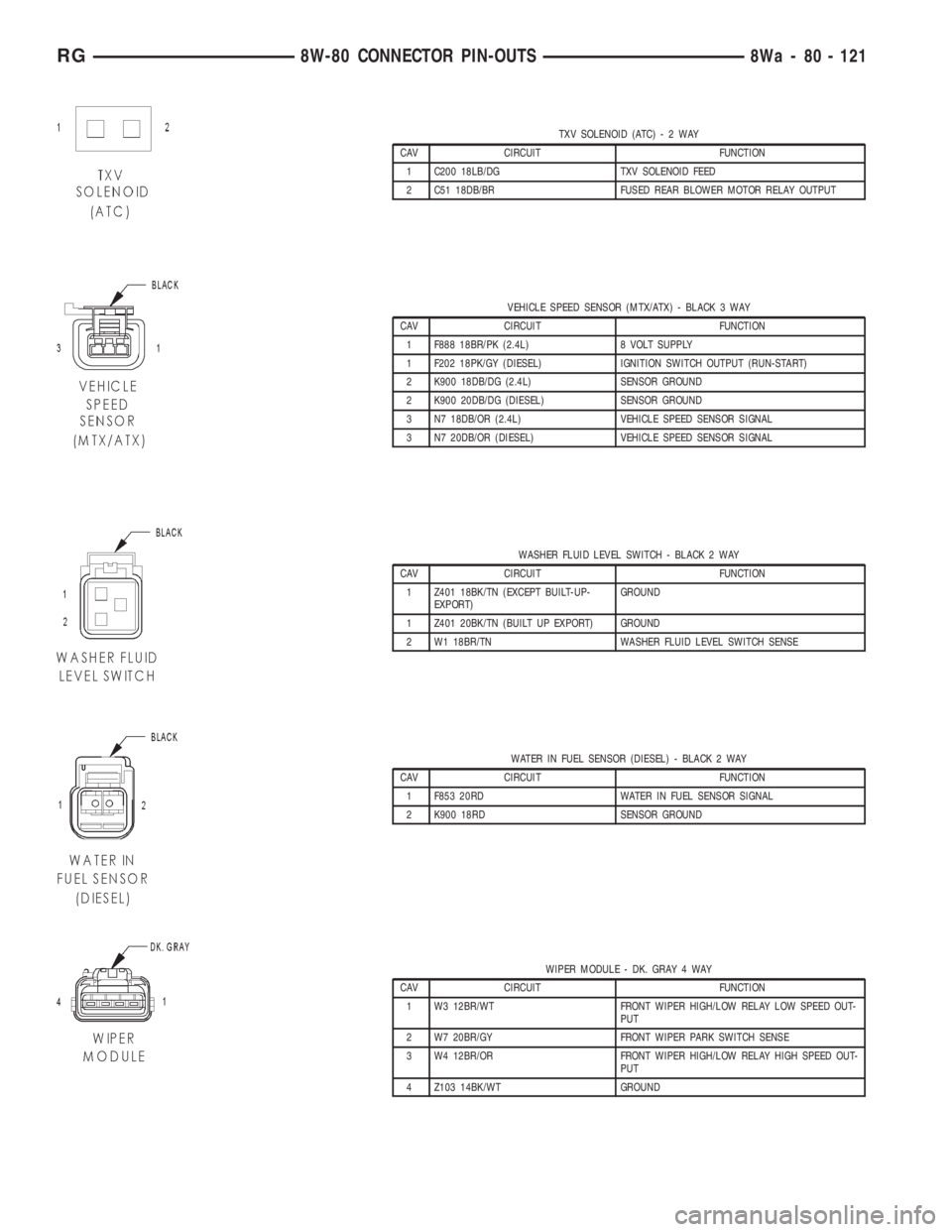
TXV SOLENOID (ATC)-2WAY
CAV CIRCUIT FUNCTION
1 C200 18LB/DG TXV SOLENOID FEED
2 C51 18DB/BR FUSED REAR BLOWER MOTOR RELAY OUTPUT
VEHICLE SPEED SENSOR (MTX/ATX) - BLACK 3 WAY
CAV CIRCUIT FUNCTION
1 F888 18BR/PK (2.4L) 8 VOLT SUPPLY
1 F202 18PK/GY (DIESEL) IGNITION SWITCH OUTPUT (RUN-START)
2 K900 18DB/DG (2.4L) SENSOR GROUND
2 K900 20DB/DG (DIESEL) SENSOR GROUND
3 N7 18DB/OR (2.4L) VEHICLE SPEED SENSOR SIGNAL
3 N7 20DB/OR (DIESEL) VEHICLE SPEED SENSOR SIGNAL
WASHER FLUID LEVEL SWITCH - BLACK 2 WAY
CAV CIRCUIT FUNCTION
1 Z401 18BK/TN (EXCEPT BUILT-UP-
EXPORT)GROUND
1 Z401 20BK/TN (BUILT UP EXPORT) GROUND
2 W1 18BR/TN WASHER FLUID LEVEL SWITCH SENSE
WATER IN FUEL SENSOR (DIESEL) - BLACK 2 WAY
CAV CIRCUIT FUNCTION
1 F853 20RD WATER IN FUEL SENSOR SIGNAL
2 K900 18RD SENSOR GROUND
WIPER MODULE - DK. GRAY 4 WAY
CAV CIRCUIT FUNCTION
1 W3 12BR/WT FRONT WIPER HIGH/LOW RELAY LOW SPEED OUT-
PUT
2 W7 20BR/GY FRONT WIPER PARK SWITCH SENSE
3 W4 12BR/OR FRONT WIPER HIGH/LOW RELAY HIGH SPEED OUT-
PUT
4 Z103 14BK/WT GROUND
RG8W-80 CONNECTOR PIN-OUTS8Wa - 80 - 121
Page 2899 of 4284
FUEL PUMP RELAY
DESCRIPTION
The fuel pump relay is located in the PDC. The
inside top of the PDC cover has a label showing relay
and fuse location.
OPERATION
The fuel pump relay supplies battery voltage to the
fuel pump. A buss bar in the Power Distribution Cen-
ter (PDC) supplies voltage to the solenoid side and
contact side of the relay. The fuel pump relay power
circuit contains a fuse between the buss bar in the
PDC and the relay. The fuse also protects the power
circuit for the Automatic Shutdown (ASD) relay. The
fuse is located in the PDC. Refer to the Wiring Dia-
grams for circuit information.
The PCM controls the fuel pump relay by switch-
ing the ground path for the solenoid side of the relay
on and off. The PCM turns the ground path off when
the ignition switch is in the Off position. When the
ignition switch is in the On position, the PCM ener-
gizes the fuel pump. If the crankshaft position sensor
does not detect engine rotation, the PCM de-ener-
gizes the relay after approximately one second.
IDLE AIR CONTROL MOTOR
DESCRIPTION
The idle air control motor is mounted on the throt-
tle body. The PCM operates the idle air control motor
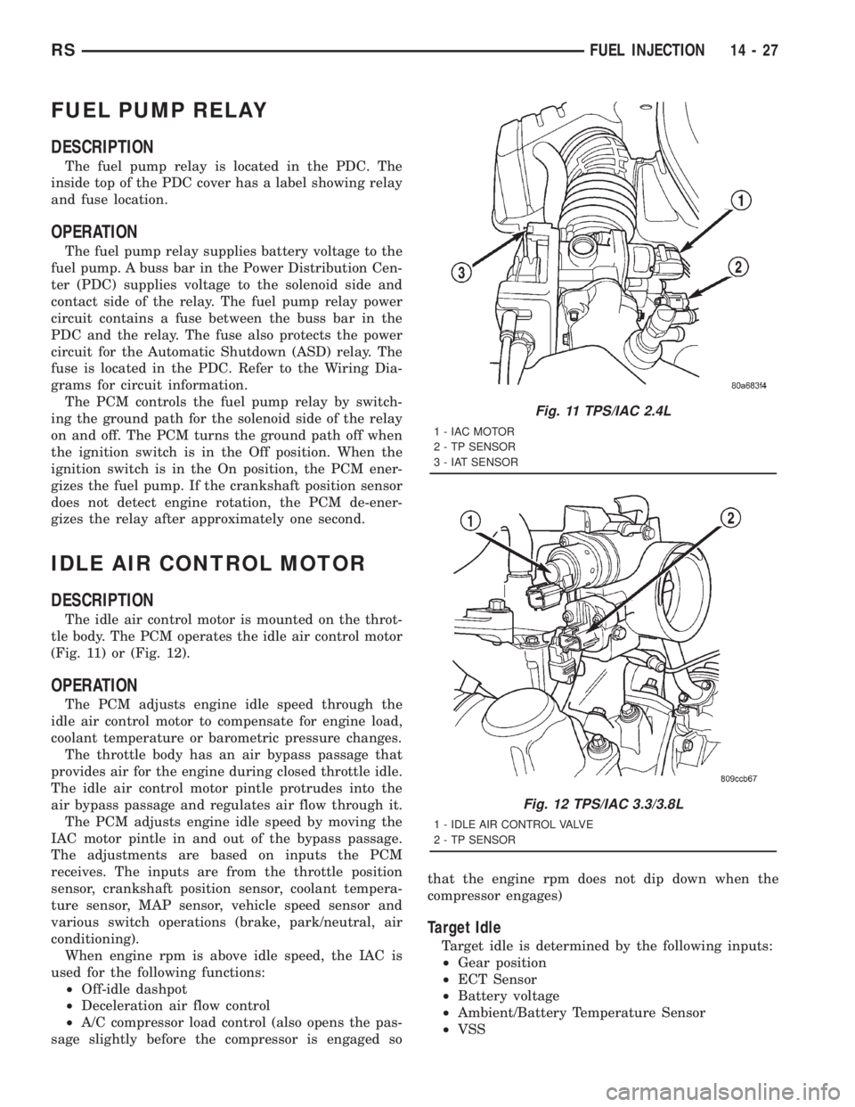
(Fig. 11) or (Fig. 12).
OPERATION
The PCM adjusts engine idle speed through the
idle air control motor to compensate for engine load,
coolant temperature or barometric pressure changes.
The throttle body has an air bypass passage that
provides air for the engine during closed throttle idle.
The idle air control motor pintle protrudes into the
air bypass passage and regulates air flow through it.
The PCM adjusts engine idle speed by moving the
IAC motor pintle in and out of the bypass passage.
The adjustments are based on inputs the PCM
receives. The inputs are from the throttle position
sensor, crankshaft position sensor, coolant tempera-
ture sensor, MAP sensor, vehicle speed sensor and
various switch operations (brake, park/neutral, air
conditioning).
When engine rpm is above idle speed, the IAC is
used for the following functions:
²Off-idle dashpot
²Deceleration air flow control
²A/C compressor load control (also opens the pas-
sage slightly before the compressor is engaged sothat the engine rpm does not dip down when the
compressor engages)
Target Idle
Target idle is determined by the following inputs:
²Gear position
²ECT Sensor
²Battery voltage
²Ambient/Battery Temperature Sensor
²VSS
Fig. 11 TPS/IAC 2.4L
1 - IAC MOTOR
2 - TP SENSOR
3 - IAT SENSOR
Fig. 12 TPS/IAC 3.3/3.8L
1 - IDLE AIR CONTROL VALVE
2 - TP SENSOR
RSFUEL INJECTION14-27
Page 3251 of 4284
TRANSMISSION CONTROL
RELAY
DESCRIPTION
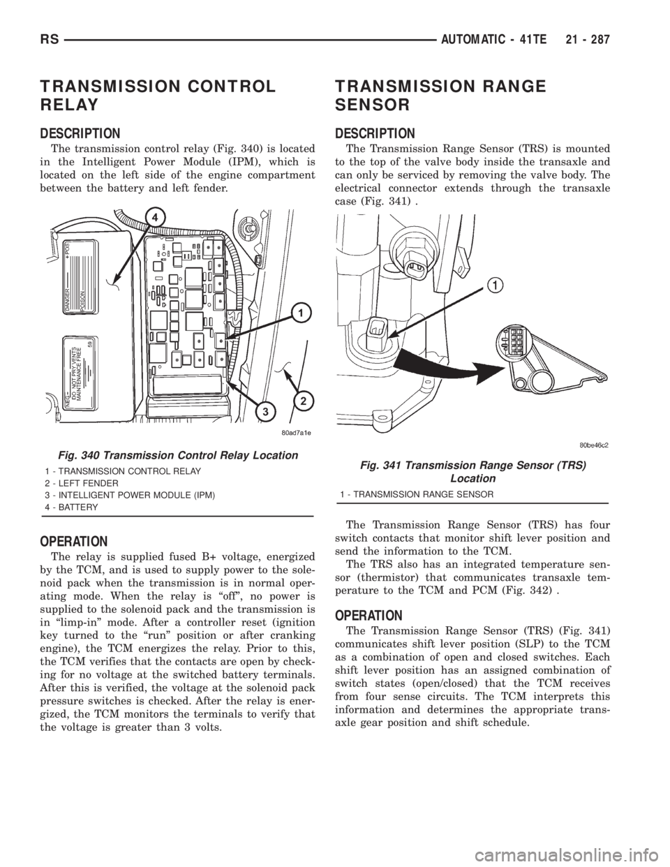
The transmission control relay (Fig. 340) is located
in the Intelligent Power Module (IPM), which is
located on the left side of the engine compartment
between the battery and left fender.
OPERATION
The relay is supplied fused B+ voltage, energized
by the TCM, and is used to supply power to the sole-
noid pack when the transmission is in normal oper-
ating mode. When the relay is ªoffº, no power is
supplied to the solenoid pack and the transmission is
in ªlimp-inº mode. After a controller reset (ignition
key turned to the ªrunº position or after cranking
engine), the TCM energizes the relay. Prior to this,
the TCM verifies that the contacts are open by check-
ing for no voltage at the switched battery terminals.
After this is verified, the voltage at the solenoid pack
pressure switches is checked. After the relay is ener-
gized, the TCM monitors the terminals to verify that
the voltage is greater than 3 volts.
TRANSMISSION RANGE
SENSOR
DESCRIPTION
The Transmission Range Sensor (TRS) is mounted
to the top of the valve body inside the transaxle and
can only be serviced by removing the valve body. The
electrical connector extends through the transaxle
case (Fig. 341) .
The Transmission Range Sensor (TRS) has four
switch contacts that monitor shift lever position and
send the information to the TCM.
The TRS also has an integrated temperature sen-
sor (thermistor) that communicates transaxle tem-
perature to the TCM and PCM (Fig. 342) .
OPERATION
The Transmission Range Sensor (TRS) (Fig. 341)
communicates shift lever position (SLP) to the TCM
as a combination of open and closed switches. Each
shift lever position has an assigned combination of
switch states (open/closed) that the TCM receives
from four sense circuits. The TCM interprets this
information and determines the appropriate trans-
axle gear position and shift schedule.
Fig. 340 Transmission Control Relay Location
1 - TRANSMISSION CONTROL RELAY
2 - LEFT FENDER
3 - INTELLIGENT POWER MODULE (IPM)
4 - BATTERYFig. 341 Transmission Range Sensor (TRS)
Location
1 - TRANSMISSION RANGE SENSOR
RSAUTOMATIC - 41TE21 - 287
Page 3643 of 4284
receptacles in the two lower finger formations of the
evaporator housing near the dash panel.
(5) Install and tighten the three screws that secure
the heater core shield to the left end of the heater/air
conditioner housing. Tighten the screws to 2 N´m (17
in. lbs.).
(6) Reinstall the silencer under the driver side end
of the instrument panel. (Refer to 23 - BODY/IN-
STRUMENT PANEL/INSTRUMENT PANEL
SILENCER - INSTALLATION).
(7) Reconnect the battery negative cable.
(8) Perform the heater-A/C control calibration pro-
cedure. (Refer to 24 - HEATING & AIR CONDITION-
ING/CONTROLS - FRONT/A/C-HEATER CONTROL
- STANDARD PROCEDURE - HEATER-A/C CON-
TROL CALIBRATION).
BLOWER MOTOR RELAY
DESCRIPTION
TERMINAL LEGEND
NUMBER IDENTIFICATION
30 COMMON FEED
85 COIL GROUND
86 COIL BATTERY
87 NORMALLY OPEN
87A NORMALLY CLOSED
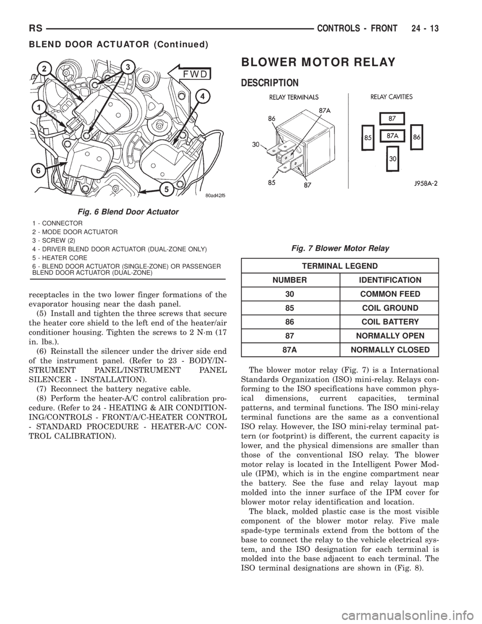
The blower motor relay (Fig. 7) is a International
Standards Organization (ISO) mini-relay. Relays con-
forming to the ISO specifications have common phys-
ical dimensions, current capacities, terminal
patterns, and terminal functions. The ISO mini-relay
terminal functions are the same as a conventional
ISO relay. However, the ISO mini-relay terminal pat-
tern (or footprint) is different, the current capacity is
lower, and the physical dimensions are smaller than
those of the conventional ISO relay. The blower
motor relay is located in the Intelligent Power Mod-
ule (IPM), which is in the engine compartment near
the battery. See the fuse and relay layout map
molded into the inner surface of the IPM cover for
blower motor relay identification and location.
The black, molded plastic case is the most visible
component of the blower motor relay. Five male
spade-type terminals extend from the bottom of the
base to connect the relay to the vehicle electrical sys-
tem, and the ISO designation for each terminal is
molded into the base adjacent to each terminal. The
ISO terminal designations are shown in (Fig. 8).
Fig. 6 Blend Door Actuator
1 - CONNECTOR
2 - MODE DOOR ACTUATOR
3 - SCREW (2)
4 - DRIVER BLEND DOOR ACTUATOR (DUAL-ZONE ONLY)
5 - HEATER CORE
6 - BLEND DOOR ACTUATOR (SINGLE-ZONE) OR PASSENGER
BLEND DOOR ACTUATOR (DUAL-ZONE)
Fig. 7 Blower Motor Relay
RSCONTROLS - FRONT24-13
BLEND DOOR ACTUATOR (Continued)
Page 3644 of 4284

OPERATION
The blower motor relay is an electromechanical
switch that uses a low current input from the Front
Control Module (FCM) to control the high current
output to the blower motor resistor (manual heater-
A/C control) or blower power module (ATC control).
The movable common feed contact point is held
against the fixed normally closed contact point by
spring pressure. When the relay coil is energized, an
electromagnetic field is produced by the coil wind-
ings. This electromagnetic field draws the movable
relay contact point away from the fixed normally
closed contact point, and holds it against the fixed
normally open contact point. When the relay coil is
de-energized, spring pressure returns the movable
contact point back against the fixed normally closed
contact point. The resistor or diode is connected in
parallel with the relay coil in the relay, and helps to
dissipate voltage spikes and electromagnetic interfer-
ence that can be generated as the electromagnetic
field of the relay coil collapses.
The blower motor relay terminals are connected to
the vehicle electrical system through a receptacle in
the Intelligent Power Module (IPM). The inputs and
outputs of the blower motor relay include:
²The common feed terminal (30) receives a bat-
tery current input from the battery through a B(+)
circuit at all times.
²The coil ground terminal (85) receives a ground
input through the front/rear blower motor relay con-
trol circuit only when the FCM electronically pulls
the control circuit to ground.
²The coil battery terminal (86) receives a battery
current input from the battery through a B(+) circuit
at all times.
²The normally open terminal (87) provides a bat-
tery current output to the blower motor resistor
(manual heater-A/C control) or blower power module
(automatic heater-A/C control) through a fuse in the
IPM on the fused front blower motor relay output cir-
cuit only when the blower motor relay coil is ener-
gized.
²The normally closed terminal (87A) is not con-
nected to any circuit in this application, but provides
a battery current output only when the blower motor
relay coil is de-energized.
Refer to the appropriate wiring information. The
wiring information includes wiring diagrams, proper
wire and connector repair procedures, further details
on wire harness routing and retention, as well as
pin-out and location views for the various wire har-
ness connectors, splices, and grounds.
DIAGNOSIS AND TESTING - BLOWER MOTOR
RELAY
The front blower motor relay (Fig. 7) is located in
the Intelligent Power Module (IPM), which is in the
engine compartment near the battery. See the fuse
and relay layout map molded into the inner surface
of the IPM cover for front blower motor relay identi-
fication and location. Remove the relay from the IPM
to perform the following tests:
(1) A relay in the de-energized position should
have continuity between terminals 87A and 30, and
no continuity between terminals 87 and 30. If OK, go
to Step 2. If not OK, replace the faulty relay.
(2) Resistance between terminals 85 and 86 (elec-
tromagnet) should be 7565 ohms. If OK, go to Step
3. If not OK, replace the faulty relay.
(3) Connect a battery to terminals 85 and 86.
There should now be continuity between terminals
30 and 87, and no continuity between terminals 87A
and 30. If OK, use a DRBIIItscan tool to perform
further diagnosis of the relay circuits. Refer to the
appropriate diagnostic information. If not OK,
replace the faulty relay.
REMOVAL
(1) Disconnect and isolate the battery negative
cable.
(2) Unlatch and remove the cover from the Intelli-
gent Power Module (IPM) (Fig. 8).
(3) See the fuse and relay layout map molded into
the inner surface of the IPM cover for front blower
motor relay identification and location.
(4) Remove the front blower motor relay from the
IPM by pulling the relay straight up.
INSTALLATION
(1) See the fuse and relay layout map molded into
the inner surface of the Intelligent Power Module
(IPM) cover for front blower motor relay identifica-
tion and location.
(2) Position the front blower motor relay to the
proper receptacle in the IPM.
(3) Align the front blower motor relay terminals
with the terminal cavities in the IPM relay recepta-
cle.
(4) Push down firmly on the front blower motor
relay until the terminals are fully seated in the ter-
minal cavities in the IPM receptacle.
(5) Install and latch the cover onto the IPM.
(6) Reconnect the battery negative cable.
24 - 14 CONTROLS - FRONTRS
BLOWER MOTOR RELAY (Continued)
Page 3651 of 4284
(11) On models with the 3.3L and 3.8L engines
only, loosely install the three screws and one nut that
secure the compressor to the engine. Tighten each of
the fasteners using the following sequence to 54 N´m
(40 ft. lbs.).
²The upper screw at the rear of the compressor.
²The lower screw at the rear of the compressor.
²The lower screw at the front of the compressor.
²The upper nut at the front of the compressor.
(12) On models with the 3.3L and 3.8L engines
only, engage the retainer on the engine wire harness
compressor clutch coil take out with the bracket on
the top of the compressor.
(13) Reconnect the engine wire harness connector
for the compressor clutch coil to the coil pigtail wire
connector on the top of the compressor.
(14) Reinstall the serpentine accessory drive belt
onto the front of the engine. (Refer to 7 - COOLING/
ACCESSORY DRIVE/DRIVE BELTS - 2.4L -
INSTALLATION) or (Refer to 7 - COOLING/ACCES-
SORY DRIVE/DRIVE BELTS - 3.3L/3.8L - INSTAL-
LATION).
(15) Lower the vehicle.
(16) Reconnect the battery negative cable.
(17) If a new clutch plate and/or clutch pulley are
being installed, the new clutch components must be
burnished. (Refer to 24 - HEATING & AIR CONDI-
TIONING/CONTROLS - FRONT/COMPRESSOR
CLUTCH - STANDARD PROCEDURE - COMPRES-
SOR CLUTCH BREAK-IN).
COMPRESSOR CLUTCH COIL
DIAGNOSIS AND TESTING - COMPRESSOR
CLUTCH COIL
The air conditioning compressor clutch coil electri-
cal circuit is controlled by the Powertrain Control
Module (PCM) through the compressor clutch relay,
which is located in the Intelligent Power Module
(IPM) in the engine compartment near the battery.
Begin testing of a suspected compressor clutch coil
problem by performing the preliminary checks.
PRELIMINARY CHECKS
(1) If the compressor clutch will not engage, verify
the refrigerant charge level. (Refer to 24 - HEATING
& AIR CONDITIONING/PLUMBING - FRONT/RE-
FRIGERANT - DIAGNOSIS AND TESTING -
REFRIGERANT CHARGE LEVEL). If the refriger-
ant charge level is OK, go to Step 2. If the refriger-
ant charge level is not OK, adjust the refrigerant
charge as required.
(2) If the a/c compressor clutch still will not
engage, disconnect the headlamp and dash wire har-
ness connector for the A/C pressure transducer andcheck for battery current at the connector with the
engine running and the heater-A/C control set to the
A/C mode. If OK, go to TESTS . If not OK, use a
DRBIIItscan tool to perform further diagnosis. Refer
to the appropriate diagnostic information.
TESTS
(1) Verify the battery state of charge. (Refer to 8 -
ELECTRICAL/BATTERY SYSTEM/BATTERY -
DIAGNOSIS AND TESTING).
(2) Connect an ammeter (0 to 10 ampere scale
selected) in series with the clutch coil feed terminal.
Connect a voltmeter (0 to 20 volt scale selected) to
measure voltage across the battery and the clutch
coil.
(3) With the heater-A/C control in the A/C mode
and the blower at low speed, start the engine and
allow it to run at a normal idle speed.
(4) The compressor clutch should engage immedi-
ately, and the clutch coil voltage should be within
two volts of the battery voltage. If the coil voltage is
not within two volts of battery voltage, test the
clutch coil feed circuit for excessive voltage drop. If
the compressor clutch does not engage, use a
DRBIIItscan tool to perform further diagnosis. Refer
to the appropriate diagnostic information.
(5) With the ambient temperature at 21É C (70É F),
the compressor clutch coil is acceptable if the current
draw is 2.0 to 3.7 amperes at 11.5 to 12.5 volts at the
clutch coil. If the voltage is more than 12.5 volts, add
electrical loads by turning on electrical accessories
until the voltage reads below 12.5 volts.
(a) If the compressor clutch coil current reading
is zero, the coil is open and must be replaced.
(b) If the compressor clutch coil current reading
is four amperes or more, the coil is shorted and
must be replaced.
COMPRESSOR CLUTCH RELAY
DESCRIPTION
The compressor clutch relay (Fig. 18) is a Interna-
tional Standards Organization (ISO) micro-relay.
Relays conforming to the ISO specifications have
common physical dimensions, current capacities, ter-
minal patterns, and terminal functions. The ISO
micro-relay terminal functions are the same as a con-
ventional ISO relay. However, the ISO micro-relay
terminal pattern (or footprint) is different, the cur-
rent capacity is lower, and the physical dimensions
are smaller than those of the conventional ISO relay.
The compressor clutch relay is located in the Intelli-
gent Power Module (IPM), which is in the engine
compartment near the battery. See the fuse and relay
layout map molded into the inner surface of the IPM
RSCONTROLS - FRONT24-21
COMPRESSOR CLUTCH (Continued)