2001 CHRYSLER VOYAGER sensor
[x] Cancel search: sensorPage 1400 of 4284
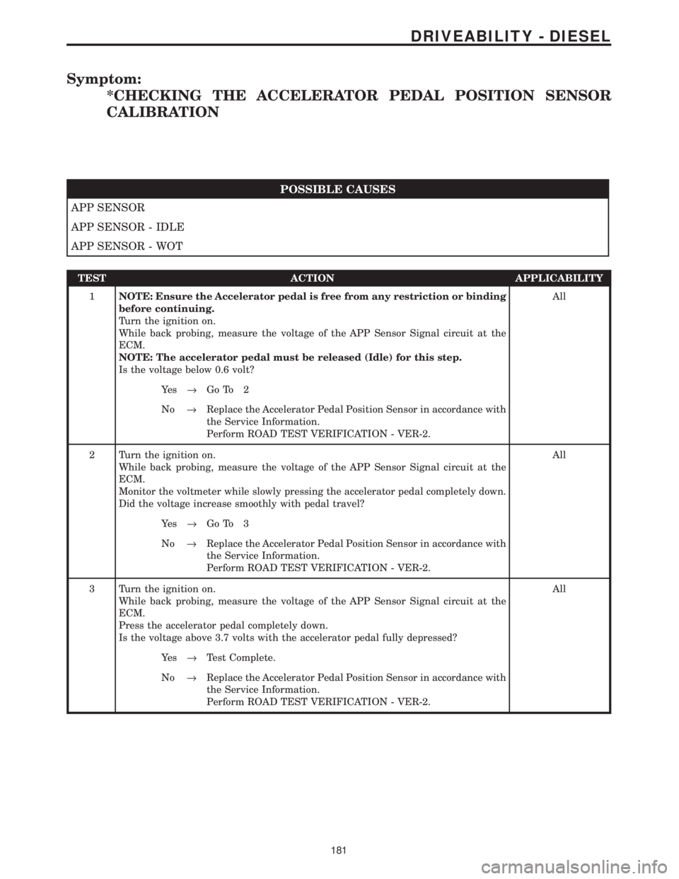
Symptom:
*CHECKING THE ACCELERATOR PEDAL POSITION SENSOR
CALIBRATION
POSSIBLE CAUSES
APP SENSOR
APP SENSOR - IDLE
APP SENSOR - WOT
TEST ACTION APPLICABILITY
1NOTE: Ensure the Accelerator pedal is free from any restriction or binding
before continuing.
Turn the ignition on.
While back probing, measure the voltage of the APP Sensor Signal circuit at the
ECM.
NOTE: The accelerator pedal must be released (Idle) for this step.
Is the voltage below 0.6 volt?All
Ye s®Go To 2
No®Replace the Accelerator Pedal Position Sensor in accordance with
the Service Information.
Perform ROAD TEST VERIFICATION - VER-2.
2 Turn the ignition on.
While back probing, measure the voltage of the APP Sensor Signal circuit at the
ECM.
Monitor the voltmeter while slowly pressing the accelerator pedal completely down.
Did the voltage increase smoothly with pedal travel?All
Ye s®Go To 3
No®Replace the Accelerator Pedal Position Sensor in accordance with
the Service Information.
Perform ROAD TEST VERIFICATION - VER-2.
3 Turn the ignition on.
While back probing, measure the voltage of the APP Sensor Signal circuit at the
ECM.
Press the accelerator pedal completely down.
Is the voltage above 3.7 volts with the accelerator pedal fully depressed?All
Ye s®Test Complete.
No®Replace the Accelerator Pedal Position Sensor in accordance with
the Service Information.
Perform ROAD TEST VERIFICATION - VER-2.
181
DRIVEABILITY - DIESEL
Page 1401 of 4284
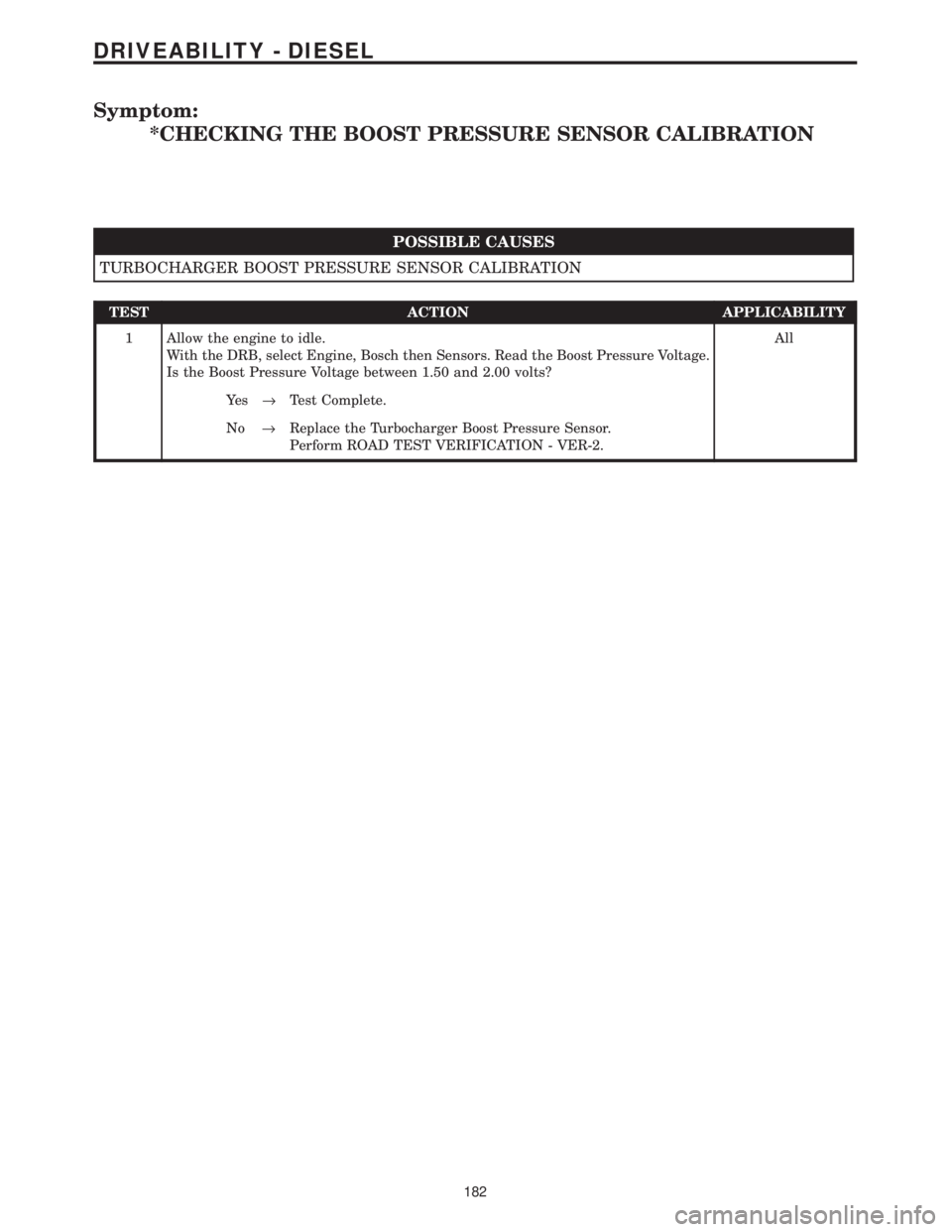
Symptom:
*CHECKING THE BOOST PRESSURE SENSOR CALIBRATION
POSSIBLE CAUSES
TURBOCHARGER BOOST PRESSURE SENSOR CALIBRATION
TEST ACTION APPLICABILITY
1 Allow the engine to idle.
With the DRB, select Engine, Bosch then Sensors. Read the Boost Pressure Voltage.
Is the Boost Pressure Voltage between 1.50 and 2.00 volts?All
Ye s®Test Complete.
No®Replace the Turbocharger Boost Pressure Sensor.
Perform ROAD TEST VERIFICATION - VER-2.
182
DRIVEABILITY - DIESEL
Page 1412 of 4284
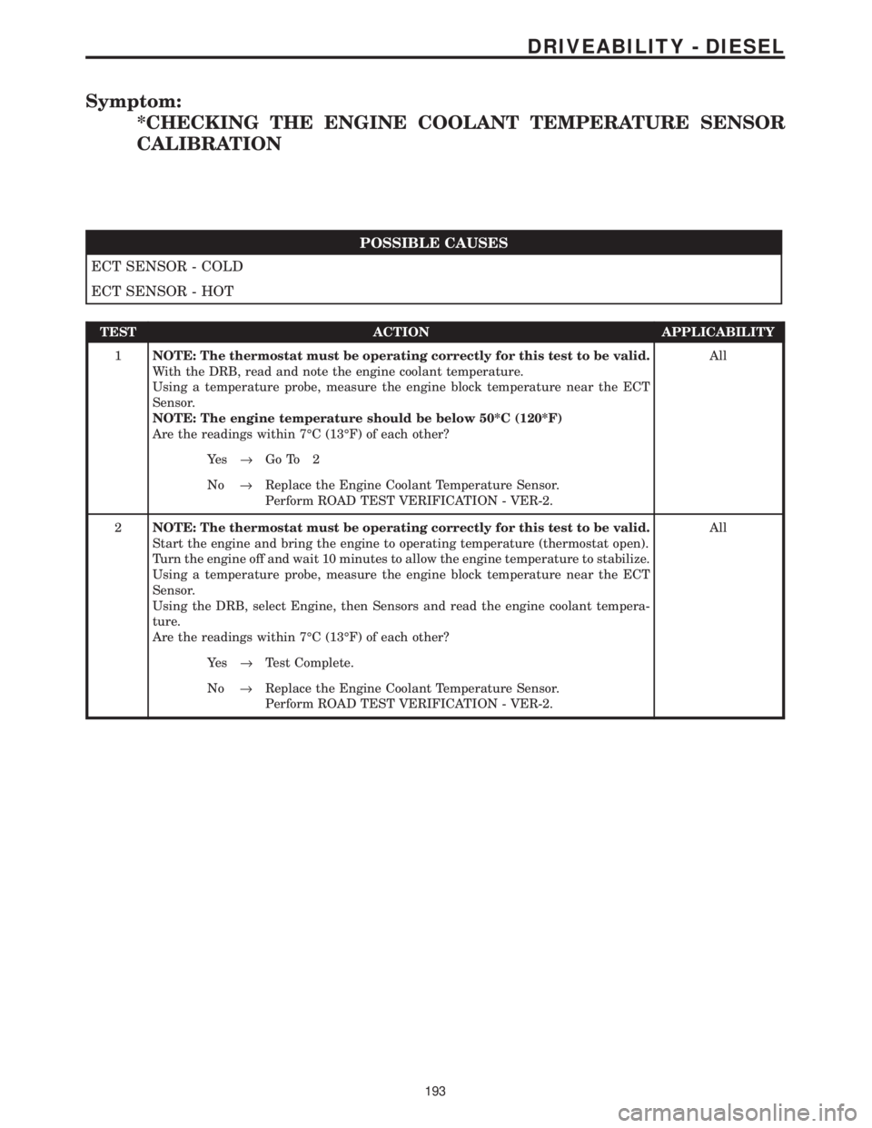
Symptom:
*CHECKING THE ENGINE COOLANT TEMPERATURE SENSOR
CALIBRATION
POSSIBLE CAUSES
ECT SENSOR - COLD
ECT SENSOR - HOT
TEST ACTION APPLICABILITY
1NOTE: The thermostat must be operating correctly for this test to be valid.
With the DRB, read and note the engine coolant temperature.
Using a temperature probe, measure the engine block temperature near the ECT
Sensor.
NOTE: The engine temperature should be below 50*C (120*F)
Are the readings within 7ÉC (13ÉF) of each other?All
Ye s®Go To 2
No®Replace the Engine Coolant Temperature Sensor.
Perform ROAD TEST VERIFICATION - VER-2.
2NOTE: The thermostat must be operating correctly for this test to be valid.
Start the engine and bring the engine to operating temperature (thermostat open).
Turn the engine off and wait 10 minutes to allow the engine temperature to stabilize.
Using a temperature probe, measure the engine block temperature near the ECT
Sensor.
Using the DRB, select Engine, then Sensors and read the engine coolant tempera-
ture.
Are the readings within 7ÉC (13ÉF) of each other?All
Ye s®Test Complete.
No®Replace the Engine Coolant Temperature Sensor.
Perform ROAD TEST VERIFICATION - VER-2.
193
DRIVEABILITY - DIESEL
Page 1413 of 4284
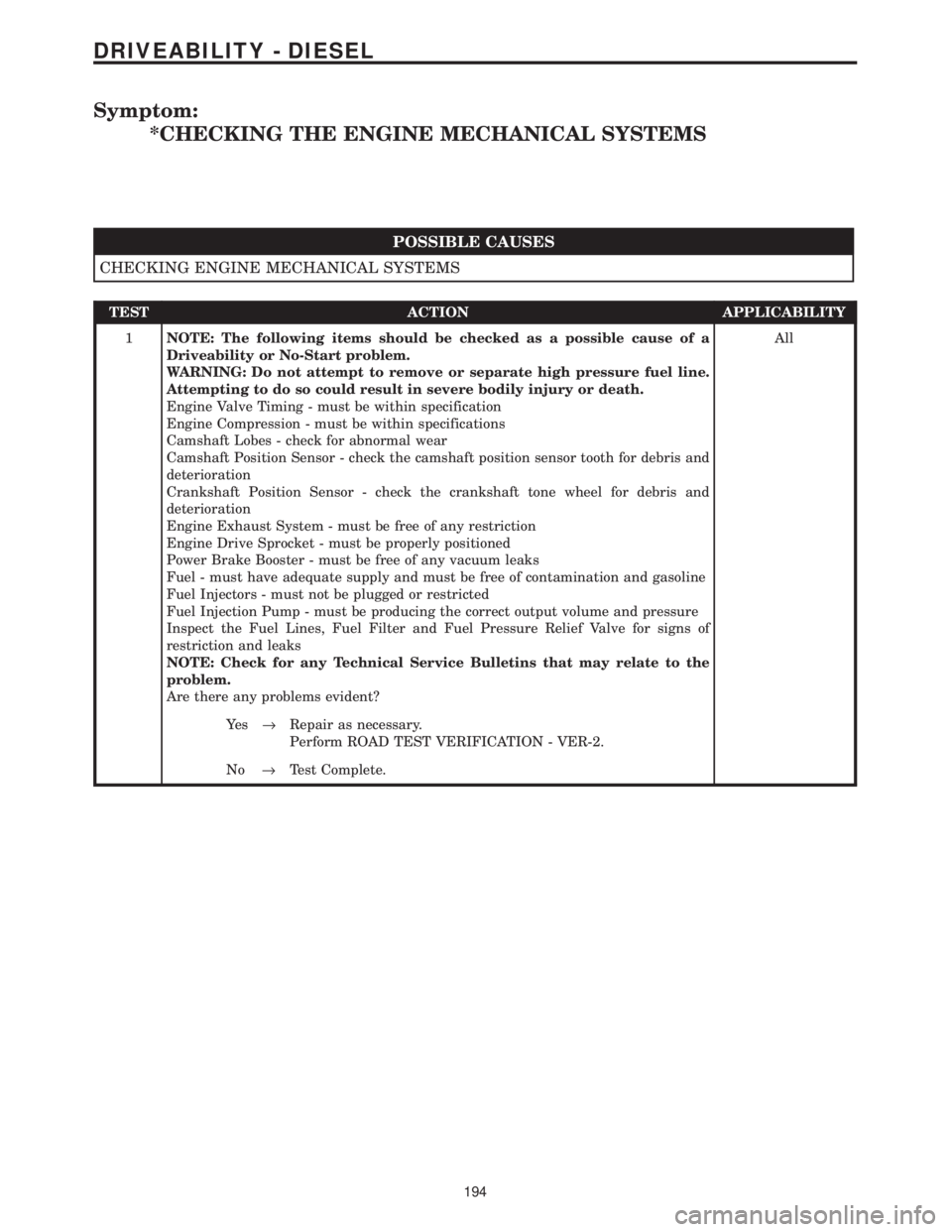
Symptom:
*CHECKING THE ENGINE MECHANICAL SYSTEMS
POSSIBLE CAUSES
CHECKING ENGINE MECHANICAL SYSTEMS
TEST ACTION APPLICABILITY
1NOTE: The following items should be checked as a possible cause of a
Driveability or No-Start problem.
WARNING: Do not attempt to remove or separate high pressure fuel line.
Attempting to do so could result in severe bodily injury or death.
Engine Valve Timing - must be within specification
Engine Compression - must be within specifications
Camshaft Lobes - check for abnormal wear
Camshaft Position Sensor - check the camshaft position sensor tooth for debris and
deterioration
Crankshaft Position Sensor - check the crankshaft tone wheel for debris and
deterioration
Engine Exhaust System - must be free of any restriction
Engine Drive Sprocket - must be properly positioned
Power Brake Booster - must be free of any vacuum leaks
Fuel - must have adequate supply and must be free of contamination and gasoline
Fuel Injectors - must not be plugged or restricted
Fuel Injection Pump - must be producing the correct output volume and pressure
Inspect the Fuel Lines, Fuel Filter and Fuel Pressure Relief Valve for signs of
restriction and leaks
NOTE: Check for any Technical Service Bulletins that may relate to the
problem.
Are there any problems evident?All
Ye s®Repair as necessary.
Perform ROAD TEST VERIFICATION - VER-2.
No®Test Complete.
194
DRIVEABILITY - DIESEL
Page 1419 of 4284
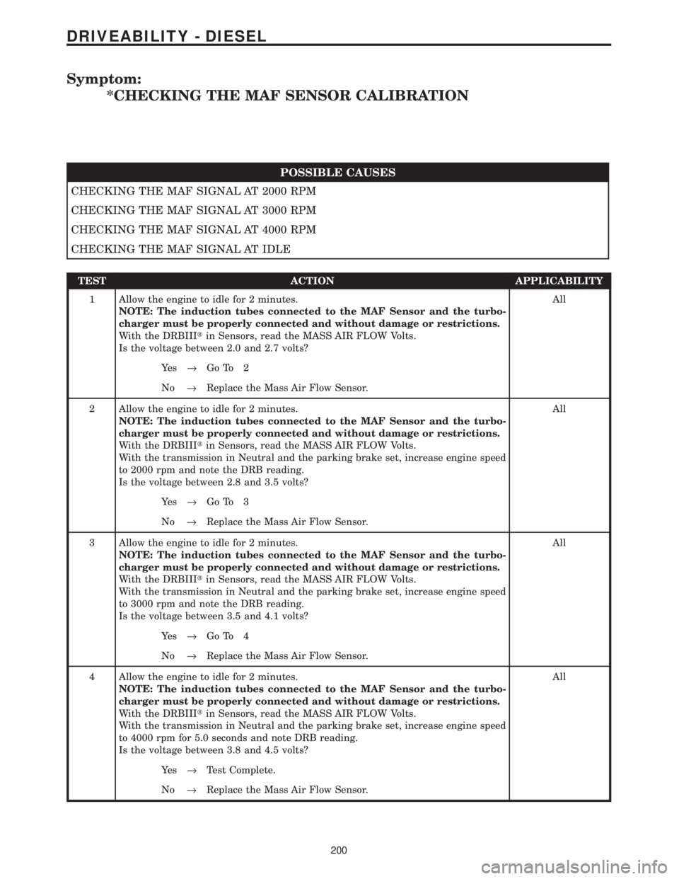
Symptom:
*CHECKING THE MAF SENSOR CALIBRATION
POSSIBLE CAUSES
CHECKING THE MAF SIGNAL AT 2000 RPM
CHECKING THE MAF SIGNAL AT 3000 RPM
CHECKING THE MAF SIGNAL AT 4000 RPM
CHECKING THE MAF SIGNAL AT IDLE
TEST ACTION APPLICABILITY
1 Allow the engine to idle for 2 minutes.
NOTE: The induction tubes connected to the MAF Sensor and the turbo-
charger must be properly connected and without damage or restrictions.
With the DRBIIItin Sensors, read the MASS AIR FLOW Volts.
Is the voltage between 2.0 and 2.7 volts?All
Ye s®Go To 2
No®Replace the Mass Air Flow Sensor.
2 Allow the engine to idle for 2 minutes.
NOTE: The induction tubes connected to the MAF Sensor and the turbo-
charger must be properly connected and without damage or restrictions.
With the DRBIIItin Sensors, read the MASS AIR FLOW Volts.
With the transmission in Neutral and the parking brake set, increase engine speed
to 2000 rpm and note the DRB reading.
Is the voltage between 2.8 and 3.5 volts?All
Ye s®Go To 3
No®Replace the Mass Air Flow Sensor.
3 Allow the engine to idle for 2 minutes.
NOTE: The induction tubes connected to the MAF Sensor and the turbo-
charger must be properly connected and without damage or restrictions.
With the DRBIIItin Sensors, read the MASS AIR FLOW Volts.
With the transmission in Neutral and the parking brake set, increase engine speed
to 3000 rpm and note the DRB reading.
Is the voltage between 3.5 and 4.1 volts?All
Ye s®Go To 4
No®Replace the Mass Air Flow Sensor.
4 Allow the engine to idle for 2 minutes.
NOTE: The induction tubes connected to the MAF Sensor and the turbo-
charger must be properly connected and without damage or restrictions.
With the DRBIIItin Sensors, read the MASS AIR FLOW Volts.
With the transmission in Neutral and the parking brake set, increase engine speed
to 4000 rpm for 5.0 seconds and note DRB reading.
Is the voltage between 3.8 and 4.5 volts?All
Ye s®Test Complete.
No®Replace the Mass Air Flow Sensor.
200
DRIVEABILITY - DIESEL
Page 1421 of 4284
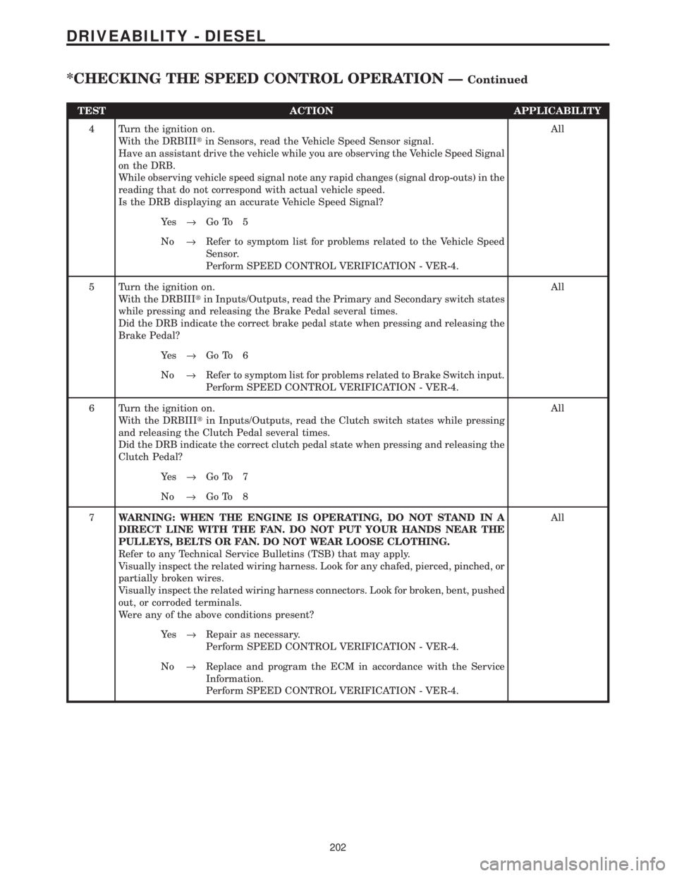
TEST ACTION APPLICABILITY
4 Turn the ignition on.
With the DRBIIItin Sensors, read the Vehicle Speed Sensor signal.
Have an assistant drive the vehicle while you are observing the Vehicle Speed Signal
on the DRB.
While observing vehicle speed signal note any rapid changes (signal drop-outs) in the
reading that do not correspond with actual vehicle speed.
Is the DRB displaying an accurate Vehicle Speed Signal?All
Ye s®Go To 5
No®Refer to symptom list for problems related to the Vehicle Speed
Sensor.
Perform SPEED CONTROL VERIFICATION - VER-4.
5 Turn the ignition on.
With the DRBIIItin Inputs/Outputs, read the Primary and Secondary switch states
while pressing and releasing the Brake Pedal several times.
Did the DRB indicate the correct brake pedal state when pressing and releasing the
Brake Pedal?All
Ye s®Go To 6
No®Refer to symptom list for problems related to Brake Switch input.
Perform SPEED CONTROL VERIFICATION - VER-4.
6 Turn the ignition on.
With the DRBIIItin Inputs/Outputs, read the Clutch switch states while pressing
and releasing the Clutch Pedal several times.
Did the DRB indicate the correct clutch pedal state when pressing and releasing the
Clutch Pedal?All
Ye s®Go To 7
No®Go To 8
7WARNING: WHEN THE ENGINE IS OPERATING, DO NOT STAND IN A
DIRECT LINE WITH THE FAN. DO NOT PUT YOUR HANDS NEAR THE
PULLEYS, BELTS OR FAN. DO NOT WEAR LOOSE CLOTHING.
Refer to any Technical Service Bulletins (TSB) that may apply.
Visually inspect the related wiring harness. Look for any chafed, pierced, pinched, or
partially broken wires.
Visually inspect the related wiring harness connectors. Look for broken, bent, pushed
out, or corroded terminals.
Were any of the above conditions present?All
Ye s®Repair as necessary.
Perform SPEED CONTROL VERIFICATION - VER-4.
No®Replace and program the ECM in accordance with the Service
Information.
Perform SPEED CONTROL VERIFICATION - VER-4.
202
DRIVEABILITY - DIESEL
*CHECKING THE SPEED CONTROL OPERATION ÐContinued
Page 1423 of 4284
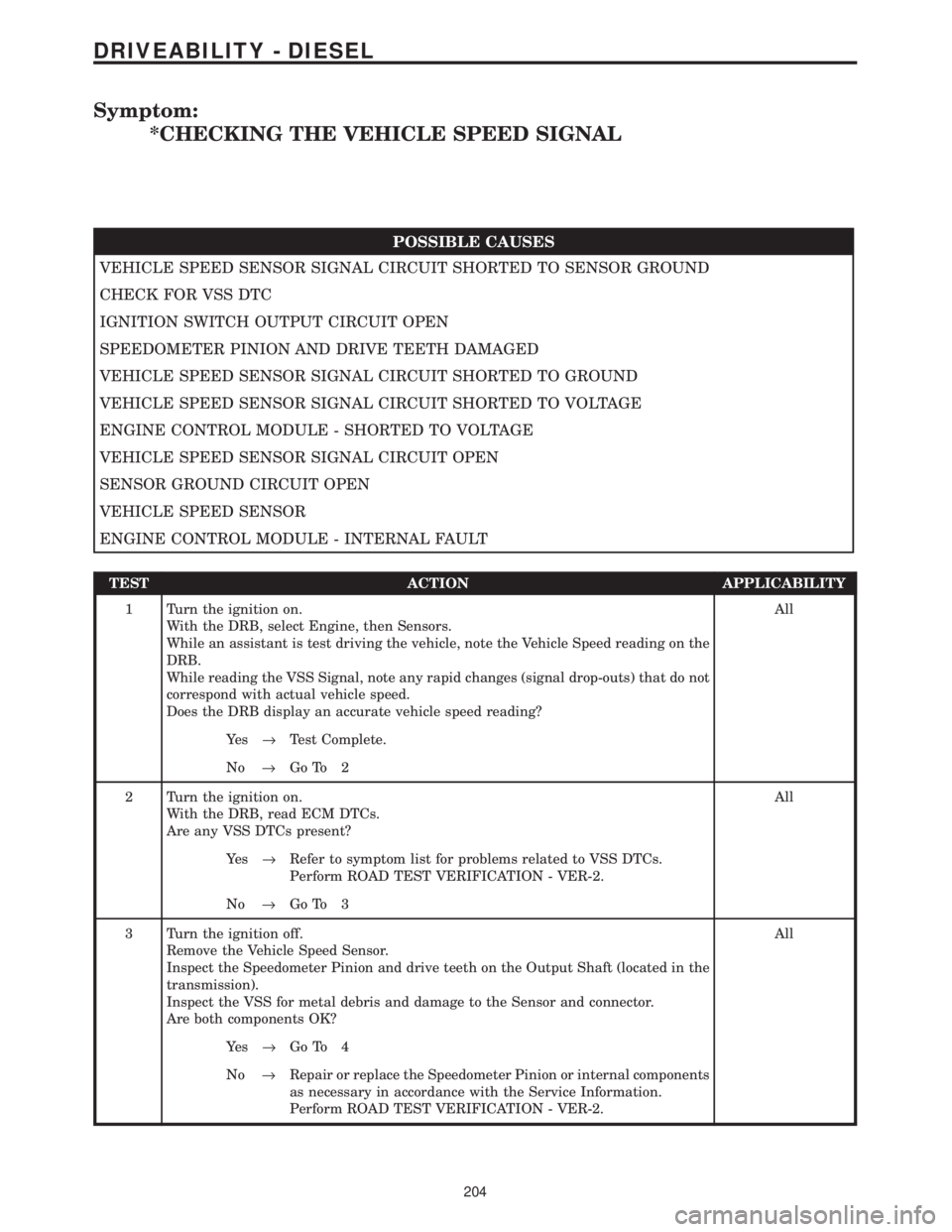
Symptom:
*CHECKING THE VEHICLE SPEED SIGNAL
POSSIBLE CAUSES
VEHICLE SPEED SENSOR SIGNAL CIRCUIT SHORTED TO SENSOR GROUND
CHECK FOR VSS DTC
IGNITION SWITCH OUTPUT CIRCUIT OPEN
SPEEDOMETER PINION AND DRIVE TEETH DAMAGED
VEHICLE SPEED SENSOR SIGNAL CIRCUIT SHORTED TO GROUND
VEHICLE SPEED SENSOR SIGNAL CIRCUIT SHORTED TO VOLTAGE
ENGINE CONTROL MODULE - SHORTED TO VOLTAGE
VEHICLE SPEED SENSOR SIGNAL CIRCUIT OPEN
SENSOR GROUND CIRCUIT OPEN
VEHICLE SPEED SENSOR
ENGINE CONTROL MODULE - INTERNAL FAULT
TEST ACTION APPLICABILITY
1 Turn the ignition on.
With the DRB, select Engine, then Sensors.
While an assistant is test driving the vehicle, note the Vehicle Speed reading on the
DRB.
While reading the VSS Signal, note any rapid changes (signal drop-outs) that do not
correspond with actual vehicle speed.
Does the DRB display an accurate vehicle speed reading?All
Ye s®Test Complete.
No®Go To 2
2 Turn the ignition on.
With the DRB, read ECM DTCs.
Are any VSS DTCs present?All
Ye s®Refer to symptom list for problems related to VSS DTCs.
Perform ROAD TEST VERIFICATION - VER-2.
No®Go To 3
3 Turn the ignition off.
Remove the Vehicle Speed Sensor.
Inspect the Speedometer Pinion and drive teeth on the Output Shaft (located in the
transmission).
Inspect the VSS for metal debris and damage to the Sensor and connector.
Are both components OK?All
Ye s®Go To 4
No®Repair or replace the Speedometer Pinion or internal components
as necessary in accordance with the Service Information.
Perform ROAD TEST VERIFICATION - VER-2.
204
DRIVEABILITY - DIESEL
Page 1424 of 4284
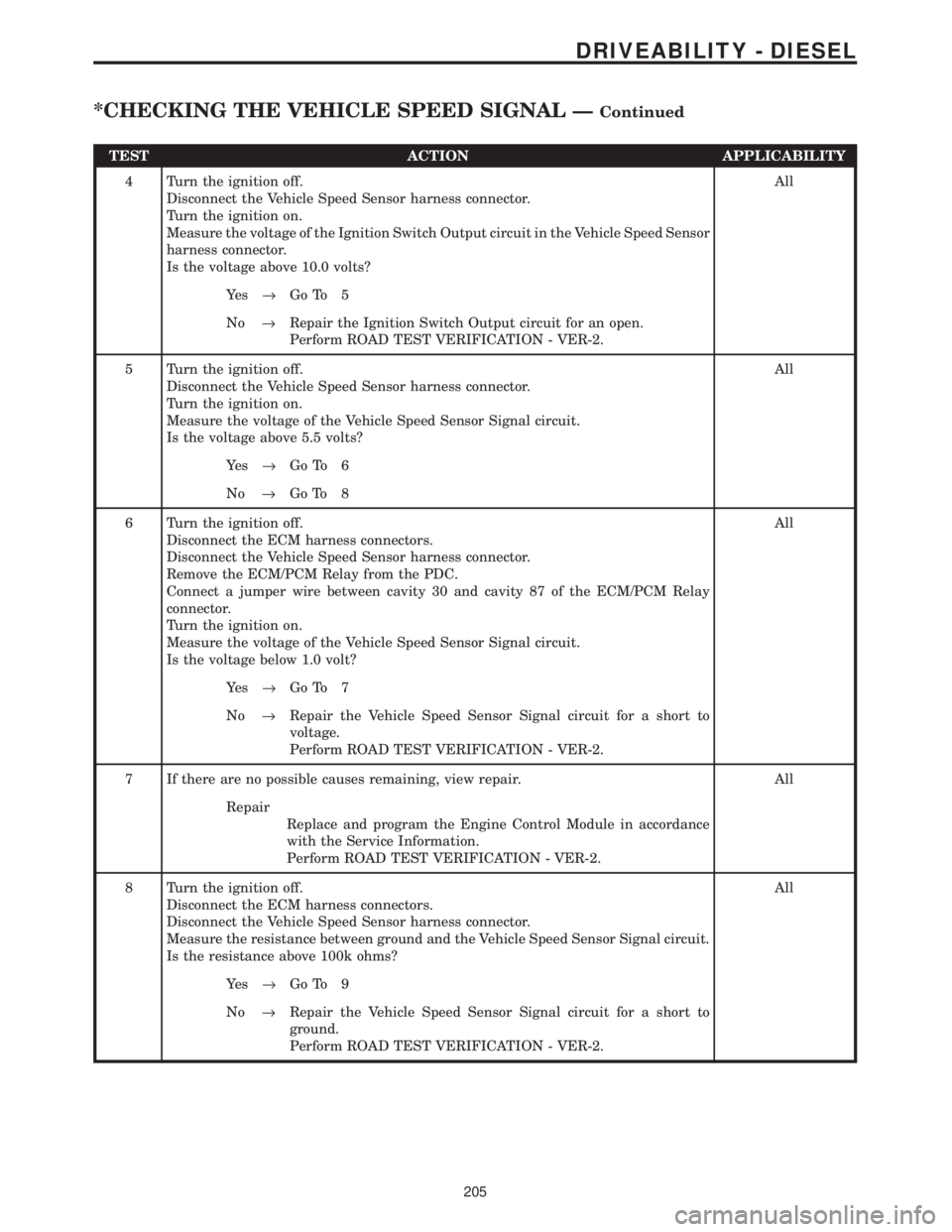
TEST ACTION APPLICABILITY
4 Turn the ignition off.
Disconnect the Vehicle Speed Sensor harness connector.
Turn the ignition on.
Measure the voltage of the Ignition Switch Output circuit in the Vehicle Speed Sensor
harness connector.
Is the voltage above 10.0 volts?All
Ye s®Go To 5
No®Repair the Ignition Switch Output circuit for an open.
Perform ROAD TEST VERIFICATION - VER-2.
5 Turn the ignition off.
Disconnect the Vehicle Speed Sensor harness connector.
Turn the ignition on.
Measure the voltage of the Vehicle Speed Sensor Signal circuit.
Is the voltage above 5.5 volts?All
Ye s®Go To 6
No®Go To 8
6 Turn the ignition off.
Disconnect the ECM harness connectors.
Disconnect the Vehicle Speed Sensor harness connector.
Remove the ECM/PCM Relay from the PDC.
Connect a jumper wire between cavity 30 and cavity 87 of the ECM/PCM Relay
connector.
Turn the ignition on.
Measure the voltage of the Vehicle Speed Sensor Signal circuit.
Is the voltage below 1.0 volt?All
Ye s®Go To 7
No®Repair the Vehicle Speed Sensor Signal circuit for a short to
voltage.
Perform ROAD TEST VERIFICATION - VER-2.
7 If there are no possible causes remaining, view repair. All
Repair
Replace and program the Engine Control Module in accordance
with the Service Information.
Perform ROAD TEST VERIFICATION - VER-2.
8 Turn the ignition off.
Disconnect the ECM harness connectors.
Disconnect the Vehicle Speed Sensor harness connector.
Measure the resistance between ground and the Vehicle Speed Sensor Signal circuit.
Is the resistance above 100k ohms?All
Ye s®Go To 9
No®Repair the Vehicle Speed Sensor Signal circuit for a short to
ground.
Perform ROAD TEST VERIFICATION - VER-2.
205
DRIVEABILITY - DIESEL
*CHECKING THE VEHICLE SPEED SIGNAL ÐContinued