Page 1425 of 4284
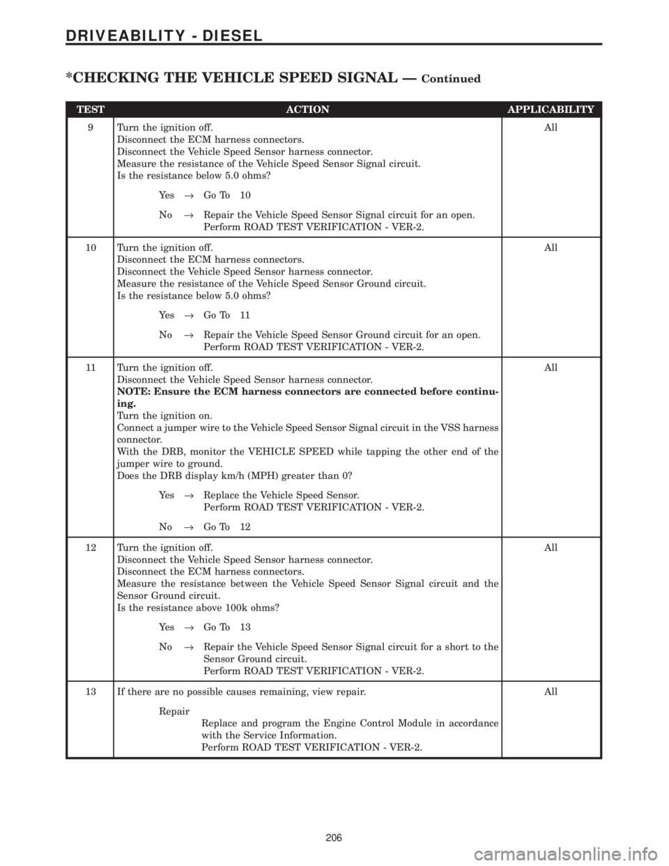
TEST ACTION APPLICABILITY
9 Turn the ignition off.
Disconnect the ECM harness connectors.
Disconnect the Vehicle Speed Sensor harness connector.
Measure the resistance of the Vehicle Speed Sensor Signal circuit.
Is the resistance below 5.0 ohms?All
Ye s®Go To 10
No®Repair the Vehicle Speed Sensor Signal circuit for an open.
Perform ROAD TEST VERIFICATION - VER-2.
10 Turn the ignition off.
Disconnect the ECM harness connectors.
Disconnect the Vehicle Speed Sensor harness connector.
Measure the resistance of the Vehicle Speed Sensor Ground circuit.
Is the resistance below 5.0 ohms?All
Ye s®Go To 11
No®Repair the Vehicle Speed Sensor Ground circuit for an open.
Perform ROAD TEST VERIFICATION - VER-2.
11 Turn the ignition off.
Disconnect the Vehicle Speed Sensor harness connector.
NOTE: Ensure the ECM harness connectors are connected before continu-
ing.
Turn the ignition on.
Connect a jumper wire to the Vehicle Speed Sensor Signal circuit in the VSS harness
connector.
With the DRB, monitor the VEHICLE SPEED while tapping the other end of the
jumper wire to ground.
Does the DRB display km/h (MPH) greater than 0?All
Ye s®Replace the Vehicle Speed Sensor.
Perform ROAD TEST VERIFICATION - VER-2.
No®Go To 12
12 Turn the ignition off.
Disconnect the Vehicle Speed Sensor harness connector.
Disconnect the ECM harness connectors.
Measure the resistance between the Vehicle Speed Sensor Signal circuit and the
Sensor Ground circuit.
Is the resistance above 100k ohms?All
Ye s®Go To 13
No®Repair the Vehicle Speed Sensor Signal circuit for a short to the
Sensor Ground circuit.
Perform ROAD TEST VERIFICATION - VER-2.
13 If there are no possible causes remaining, view repair. All
Repair
Replace and program the Engine Control Module in accordance
with the Service Information.
Perform ROAD TEST VERIFICATION - VER-2.
206
DRIVEABILITY - DIESEL
*CHECKING THE VEHICLE SPEED SIGNAL ÐContinued
Page 1426 of 4284
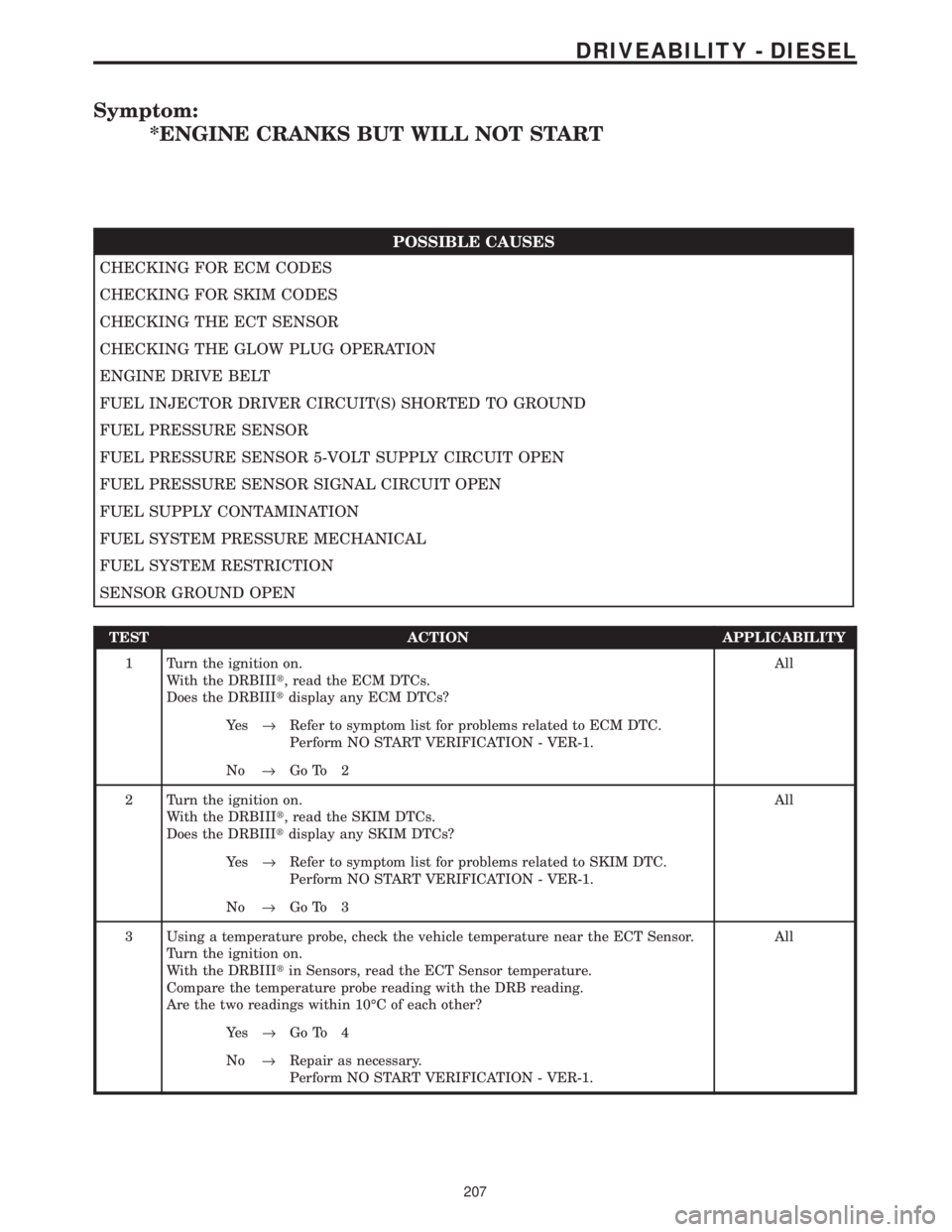
Symptom:
*ENGINE CRANKS BUT WILL NOT START
POSSIBLE CAUSES
CHECKING FOR ECM CODES
CHECKING FOR SKIM CODES
CHECKING THE ECT SENSOR
CHECKING THE GLOW PLUG OPERATION
ENGINE DRIVE BELT
FUEL INJECTOR DRIVER CIRCUIT(S) SHORTED TO GROUND
FUEL PRESSURE SENSOR
FUEL PRESSURE SENSOR 5-VOLT SUPPLY CIRCUIT OPEN
FUEL PRESSURE SENSOR SIGNAL CIRCUIT OPEN
FUEL SUPPLY CONTAMINATION
FUEL SYSTEM PRESSURE MECHANICAL
FUEL SYSTEM RESTRICTION
SENSOR GROUND OPEN
TEST ACTION APPLICABILITY
1 Turn the ignition on.
With the DRBIIIt, read the ECM DTCs.
Does the DRBIIItdisplay any ECM DTCs?All
Ye s®Refer to symptom list for problems related to ECM DTC.
Perform NO START VERIFICATION - VER-1.
No®Go To 2
2 Turn the ignition on.
With the DRBIIIt, read the SKIM DTCs.
Does the DRBIIItdisplay any SKIM DTCs?All
Ye s®Refer to symptom list for problems related to SKIM DTC.
Perform NO START VERIFICATION - VER-1.
No®Go To 3
3 Using a temperature probe, check the vehicle temperature near the ECT Sensor.
Turn the ignition on.
With the DRBIIItin Sensors, read the ECT Sensor temperature.
Compare the temperature probe reading with the DRB reading.
Are the two readings within 10ÉC of each other?All
Ye s®Go To 4
No®Repair as necessary.
Perform NO START VERIFICATION - VER-1.
207
DRIVEABILITY - DIESEL
Page 1427 of 4284
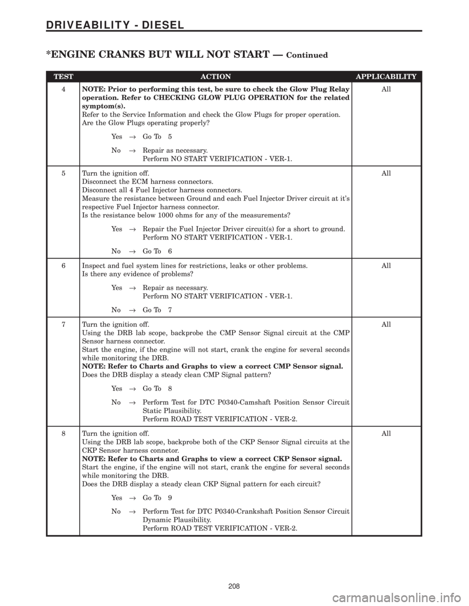
TEST ACTION APPLICABILITY
4NOTE: Prior to performing this test, be sure to check the Glow Plug Relay
operation. Refer to CHECKING GLOW PLUG OPERATION for the related
symptom(s).
Refer to the Service Information and check the Glow Plugs for proper operation.
Are the Glow Plugs operating properly?All
Ye s®Go To 5
No®Repair as necessary.
Perform NO START VERIFICATION - VER-1.
5 Turn the ignition off.
Disconnect the ECM harness connectors.
Disconnect all 4 Fuel Injector harness connectors.
Measure the resistance between Ground and each Fuel Injector Driver circuit at it's
respective Fuel Injector harness connector.
Is the resistance below 1000 ohms for any of the measurements?All
Ye s®Repair the Fuel Injector Driver circuit(s) for a short to ground.
Perform NO START VERIFICATION - VER-1.
No®Go To 6
6 Inspect and fuel system lines for restrictions, leaks or other problems.
Is there any evidence of problems?All
Ye s®Repair as necessary.
Perform NO START VERIFICATION - VER-1.
No®Go To 7
7 Turn the ignition off.
Using the DRB lab scope, backprobe the CMP Sensor Signal circuit at the CMP
Sensor harness connector.
Start the engine, if the engine will not start, crank the engine for several seconds
while monitoring the DRB.
NOTE: Refer to Charts and Graphs to view a correct CMP Sensor signal.
Does the DRB display a steady clean CMP Signal pattern?All
Ye s®Go To 8
No®Perform Test for DTC P0340-Camshaft Position Sensor Circuit
Static Plausibility.
Perform ROAD TEST VERIFICATION - VER-2.
8 Turn the ignition off.
Using the DRB lab scope, backprobe both of the CKP Sensor Signal circuits at the
CKP Sensor harness connetor.
NOTE: Refer to Charts and Graphs to view a correct CKP Sensor signal.
Start the engine, if the engine will not start, crank the engine for several seconds
while monitoring the DRB.
Does the DRB display a steady clean CKP Signal pattern for each circuit?All
Ye s®Go To 9
No®Perform Test for DTC P0340-Crankshaft Position Sensor Circuit
Dynamic Plausibility.
Perform ROAD TEST VERIFICATION - VER-2.
208
DRIVEABILITY - DIESEL
*ENGINE CRANKS BUT WILL NOT START ÐContinued
Page 1428 of 4284
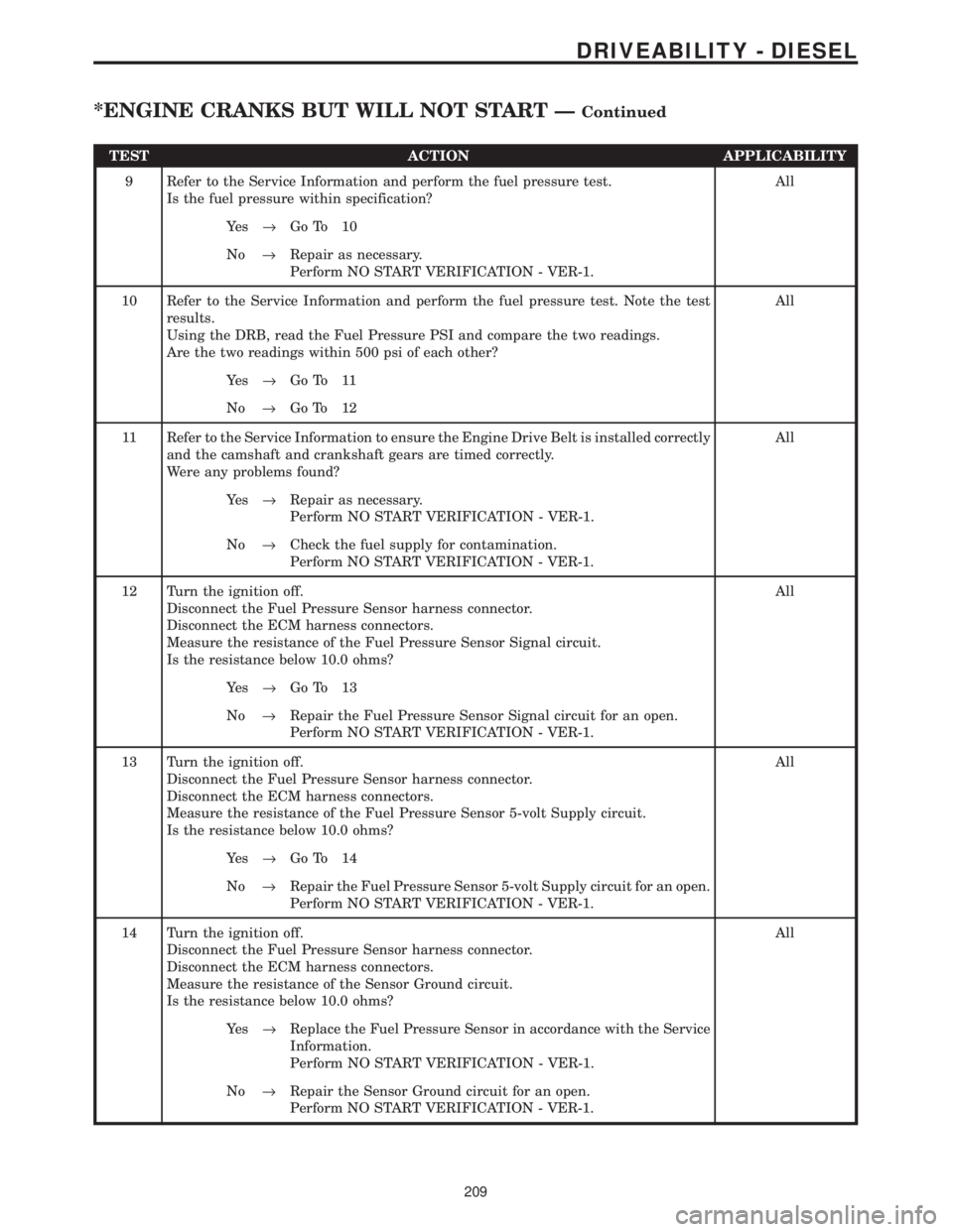
TEST ACTION APPLICABILITY
9 Refer to the Service Information and perform the fuel pressure test.
Is the fuel pressure within specification?All
Ye s®Go To 10
No®Repair as necessary.
Perform NO START VERIFICATION - VER-1.
10 Refer to the Service Information and perform the fuel pressure test. Note the test
results.
Using the DRB, read the Fuel Pressure PSI and compare the two readings.
Are the two readings within 500 psi of each other?All
Ye s®Go To 11
No®Go To 12
11 Refer to the Service Information to ensure the Engine Drive Belt is installed correctly
and the camshaft and crankshaft gears are timed correctly.
Were any problems found?All
Ye s®Repair as necessary.
Perform NO START VERIFICATION - VER-1.
No®Check the fuel supply for contamination.
Perform NO START VERIFICATION - VER-1.
12 Turn the ignition off.
Disconnect the Fuel Pressure Sensor harness connector.
Disconnect the ECM harness connectors.
Measure the resistance of the Fuel Pressure Sensor Signal circuit.
Is the resistance below 10.0 ohms?All
Ye s®Go To 13
No®Repair the Fuel Pressure Sensor Signal circuit for an open.
Perform NO START VERIFICATION - VER-1.
13 Turn the ignition off.
Disconnect the Fuel Pressure Sensor harness connector.
Disconnect the ECM harness connectors.
Measure the resistance of the Fuel Pressure Sensor 5-volt Supply circuit.
Is the resistance below 10.0 ohms?All
Ye s®Go To 14
No®Repair the Fuel Pressure Sensor 5-volt Supply circuit for an open.
Perform NO START VERIFICATION - VER-1.
14 Turn the ignition off.
Disconnect the Fuel Pressure Sensor harness connector.
Disconnect the ECM harness connectors.
Measure the resistance of the Sensor Ground circuit.
Is the resistance below 10.0 ohms?All
Ye s®Replace the Fuel Pressure Sensor in accordance with the Service
Information.
Perform NO START VERIFICATION - VER-1.
No®Repair the Sensor Ground circuit for an open.
Perform NO START VERIFICATION - VER-1.
209
DRIVEABILITY - DIESEL
*ENGINE CRANKS BUT WILL NOT START ÐContinued
Page 1448 of 4284
8.6 SENSORS
C
O
M
P
O
N
E
N
T
L
O
C
A
T
I
O
N
S
229
COMPONENT LOCATIONS
Page 1449 of 4284
8.7 SWITCHES
C
O
M
P
O
N
E
N
T
L
O
C
A
T
I
O
N
S
230
COMPONENT LOCATIONS
8.6 SENSORS (Continued)
Page 1450 of 4284
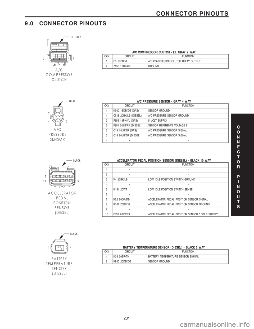
9.0 CONNECTOR PINOUTS
A/C COMPRESSOR CLUTCH - LT. GRAY 2 WAYCAV CIRCUIT FUNCTION
1 C3 18DB/YL A/C COMPRESSOR CLUTCH RELAY OUTPUT
2 Z153 18BK/GY GROUND
A/C PRESSURE SENSOR - GRAY 4 WAYCAV CIRCUIT FUNCTION
1 K900 18DB/DG (GAS) SENSOR GROUND
1 C918 20BK/LB (DIESEL) A/C PRESSURE SENSOR GROUND
2 F855 18PK/YL (GAS) 5 VOLT SUPPLY
2 F851 20LB/PK (DIESEL) SENSOR REFERENCE VOLTAGE B
3 C18 18LB/BR (GAS) A/C PRESSURE SENSOR SIGNAL
3 C18 20LB/BR (DIESEL) A/C PRESSURE SENSOR SIGNAL
4- -
ACCELERATOR PEDAL POSITION SENSOR (DIESEL) - BLACK 10 WAYCAV CIRCUIT FUNCTION
1- -
2- -
3 K4 20BK/LB LOW IDLE POSITION SWITCH GROUND
4- -
5 K151 20WT LOW IDLE POSITION SWITCH SENSE
6- -
7 K22 20OR/DB ACCELERATOR PEDAL POSITION SENSOR SIGNAL
8 K167 20BR/YL ACCELERATOR PEDAL POSITION SENSOR GROUND
9- -
10 F852 20VT/PK ACCELERATOR PEDAL POSITION SENSOR 5 VOLT SUPPLY
BATTERY TEMPERATURE SENSOR (DIESEL) - BLACK 2 WAYCAV CIRCUIT FUNCTION
1 K25 20BR/TN BATTERY TEMPERATURE SENSOR SIGNAL
2 K900 20DB/DG SENSOR GROUND
C
O
N
N
E
C
T
O
R
P
I
N
O
U
T
S
231
CONNECTOR PINOUTS
Page 1451 of 4284
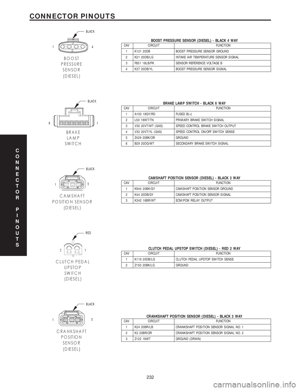
BOOST PRESSURE SENSOR (DIESEL) - BLACK 4 WAYCAV CIRCUIT FUNCTION
1 K121 20DB BOOST PRESSURE SENSOR GROUND
2 K21 20DB/LG INTAKE AIR TEMPERATURE SENSOR SIGNAL
3 F851 18LB/PK SENSOR REFERENCE VOLTAGE B
4 K37 20DB/YL BOOST PRESSURE SENSOR SIGNAL
BRAKE LAMP SWITCH - BLACK 6 WAYCAV CIRCUIT FUNCTION
1 A103 18GY/RD FUSED B(+)
2 L50 18WT/TN PRIMARY BRAKE SWITCH SIGNAL
3 V30 20VT/WT (GAS) SPEED CONTROL BRAKE SWITCH OUTPUT
4 V32 20VT/YL (GAS) SPEED CONTROL ON/OFF SWITCH SENSE
5 Z429 20BK/OR GROUND
6 B29 20DG/WT SECONDARY BRAKE SWITCH SIGNAL
CAMSHAFT POSITION SENSOR (DIESEL) - BLACK 3 WAYCAV CIRCUIT FUNCTION
1 K944 20BK/GY CAMSHAFT POSITION SENSOR GROUND
2 K44 20DB/GY CAMSHAFT POSITION SENSOR SIGNAL
3 K342 16BR/WT ECM/PCM RELAY OUTPUT
CLUTCH PEDAL UPSTOP SWITCH (DIESEL) - RED 2 WAYCAV CIRCUIT FUNCTION
1 K119 20DB/LG CLUTCH PEDAL UPSTOP SWITCH SENSE
2 Z150 20BK/LG GROUND
CRANKSHAFT POSITION SENSOR (DIESEL) - BLACK 3 WAYCAV CIRCUIT FUNCTION
1 K24 20BR/LB CRANKSHAFT POSITION SENSOR SIGNAL NO. 1
2 K3 20BR/OR CRANKSHAFT POSITION SENSOR SIGNAL NO. 2
3 Z122 18WT GROUND (DRAIN)
C
O
N
N
E
C
T
O
R
P
I
N
O
U
T
S
232
CONNECTOR PINOUTS