2001 CHRYSLER VOYAGER sensor
[x] Cancel search: sensorPage 1694 of 4284
tem enters the ABS mode. During ABS braking,
hydraulic pressure in the four wheel circuits is mod-
ulated to prevent any wheel from locking. Each
wheel circuit is designed with a set of electric sole-
noids to allow modulation, although for vehicle sta-
bility, both rear wheel solenoids receive the same
electrical signal. Wheel lockup may be perceived at
the very end of an ABS stop and is considered nor-
mal.
During an ABS stop, the brakes hydraulic system
is still diagonally split. However, the brake system
pressure is further split into three control channels.
During antilock operation of the vehicle's brake sys-
tem, the front wheels are controlled independently
and are on two separate control channels, and the
rear wheels of the vehicle are controlled together.
The system can build and release pressure at each
wheel, depending on signals generated by the wheel
speed sensors (WSS) at each wheel and received at
the controller antilock brake (CAB).
NOISE AND BRAKE PEDAL FEEL
During ABS braking, some brake pedal movement
may be felt. In addition, ABS braking will create
ticking, popping, or groaning noises heard by the
driver. This is normal and is due to pressurized fluid
being transferred between the master cylinder and
the brakes. If ABS operation occurs during hard
braking, some pulsation may be felt in the vehicle
body due to fore and aft movement of the suspension
as brake pressures are modulated.
At the end of an ABS stop, ABS is turned off when
the vehicle is slowed to a speed of 3±4 mph. There
may be a slight brake pedal drop anytime that the
ABS is deactivated, such as at the end of the stop
when the vehicle speed is less than 3 mph or during
an ABS stop where ABS is no longer required. These
conditions exist when a vehicle is being stopped on a
road surface with patches of ice, loose gravel, or sand
on it. Also, stopping a vehicle on a bumpy road sur-
face activates ABS because of the wheel hop caused
by the bumps.
TIRE NOISE AND MARKS
Although the ABS system prevents complete wheel
lockup, some wheel slip is desired in order to achieve
optimum braking performance. Wheel slip is defined
as follows: 0 percent slip means the wheel is rolling
freely and 100 percent slip means the wheel is fully
locked. During brake pressure modulation, wheel slip
is allowed to reach up to 25±30 percent. This means
that the wheel rolling velocity is 25±30 percent less
than that of a free rolling wheel at a given vehicle
speed. This slip may result in some tire chirping,
depending on the road surface. This sound should not
be interpreted as total wheel lockup.Complete wheel lockup normally leaves black tire
marks on dry pavement. The ABS will not leave dark
black tire marks since the wheel never reaches a
fully locked condition. However, tire marks may be
noticeable as light patched marks.
START-UP CYCLE
When the ignition is turned on, a popping sound
and a slight brake pedal movement may be noticed.
The ABS warning lamp will also be on for up to 5
seconds after the ignition is turned on. When the
vehicle is first driven off, a humming may be heard
or felt by the driver at approximately 20±40 kph
(12±25 mph). All of these conditions are a normal
function of ABS as the system is performing a diag-
nosis check.
PREMATURE ABS CYCLING
Symptoms of premature ABS cycling include: click-
ing sounds from the solenoid valves; pump/motor
running; and pulsations in the brake pedal. Prema-
ture ABS cycling can occur at any braking rate of the
vehicle and on any type of road surface. Neither the
red BRAKE warning lamp, nor the amber ABS warn-
ing lamp, illuminate and no fault codes are stored in
the CAB.
Premature ABS cycling is a condition that needs to
be correctly assessed when diagnosing problems with
the antilock brake system. It may be necessary to use
a DRB scan tool to detect and verify premature ABS
cycling.
Check the following common causes when diagnos-
ing premature ABS cycling: damaged tone wheels;
incorrect tone wheels; damaged steering knuckle
wheel speed sensor mounting bosses; loose wheel
speed sensor mounting bolts; excessive tone wheel
runout; or an excessively large tone wheel-to-wheel
speed sensor air gap. Give special attention to these
components when diagnosing a vehicle exhibiting
premature ABS cycling.
After diagnosing the defective component, repair or
replace it as required. When the component repair or
replacement is completed, test drive the vehicle to
verify that premature ABS cycling has been cor-
rected.
OPERATION - ELECTRONIC BRAKE
DISTRIBUTION
Upon entry into EBD the inlet valve for the rear
brake circuit is switched on so that the fluid supply
from the master cylinder is shut off. In order to
decrease the rear brake pressure, the outlet valve for
the rear brake circuit is pulsed. This allows fluid to
enter the low pressure accumulator (LPA) in the
hydraulic control unit (HCU) resulting in a drop in
fluid pressure to the rear brakes. In order to increase
5 - 68 BRAKES - ABSRS
BRAKES - ABS (Continued)
Page 1697 of 4284
SPECIFICATIONS
SPECIFICATIONS - ABS FASTENER TORQUE
(Refer to 5 - BRAKES - BASE - SPECIFICA-
TIONS)
TONE WHEEL RUNOUT
DESCRIPTION SPECIFICATION
Front Tone Wheel
Maximum Runout0.15 mm (0.006 in.)
Rear Tone Wheel
Maximum Runout0.15 mm (0.006 in.)
WHEEL SPEED SENSOR AIR GAP
DESCRIPTION SPECIFICATION
Front Sensor0.35 ± 1.20 mm
0.014 ± 0.047 in.
Rear Sensor0.40 ± 1.20 mm
0.016 ± 0.047 in.
FRONT WHEEL SPEED
SENSOR
REMOVAL - WHEEL SPEED SENSOR (FRONT)
(1) Raise vehicle. (Refer to LUBRICATION &
MAINTENANCE/HOISTING - STANDARD PROCE-
DURE)
(2) Remove the tire and wheel assembly.
(3) Remove the sensor cable routing clamp screws.
CAUTION: When disconnecting the wheel speed
sensor from vehicle wiring harness, be careful not
to damage pins on connector
(4) Remove speed sensor cable grommets from
intermediate bracket on strut.
(5) Disconnect speed sensor cable from vehicle wir-
ing harness behind fender well shield.
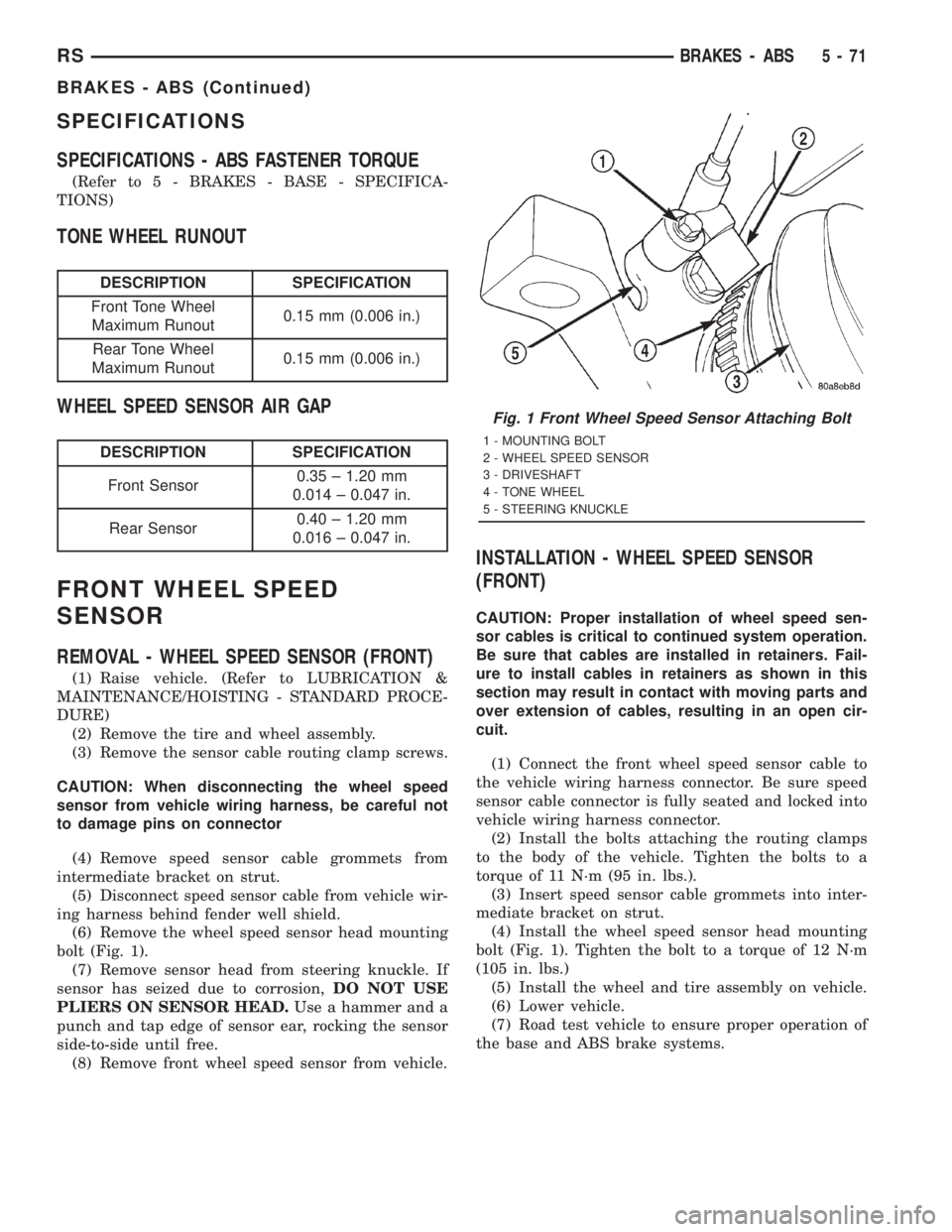
(6) Remove the wheel speed sensor head mounting
bolt (Fig. 1).
(7) Remove sensor head from steering knuckle. If
sensor has seized due to corrosion,DO NOT USE
PLIERS ON SENSOR HEAD.Use a hammer and a
punch and tap edge of sensor ear, rocking the sensor
side-to-side until free.
(8) Remove front wheel speed sensor from vehicle.
INSTALLATION - WHEEL SPEED SENSOR
(FRONT)
CAUTION: Proper installation of wheel speed sen-
sor cables is critical to continued system operation.
Be sure that cables are installed in retainers. Fail-
ure to install cables in retainers as shown in this
section may result in contact with moving parts and
over extension of cables, resulting in an open cir-
cuit.
(1) Connect the front wheel speed sensor cable to
the vehicle wiring harness connector. Be sure speed
sensor cable connector is fully seated and locked into
vehicle wiring harness connector.
(2) Install the bolts attaching the routing clamps
to the body of the vehicle. Tighten the bolts to a
torque of 11 N´m (95 in. lbs.).
(3) Insert speed sensor cable grommets into inter-
mediate bracket on strut.
(4) Install the wheel speed sensor head mounting
bolt (Fig. 1). Tighten the bolt to a torque of 12 N´m
(105 in. lbs.)
(5) Install the wheel and tire assembly on vehicle.
(6) Lower vehicle.
(7) Road test vehicle to ensure proper operation of
the base and ABS brake systems.
Fig. 1 Front Wheel Speed Sensor Attaching Bolt
1 - MOUNTING BOLT
2 - WHEEL SPEED SENSOR
3 - DRIVESHAFT
4 - TONE WHEEL
5 - STEERING KNUCKLE
RSBRAKES - ABS5-71
BRAKES - ABS (Continued)
Page 1698 of 4284
REAR WHEEL SPEED SENSOR
-AWD
REMOVAL - WHEEL SPEED SENSOR
(REAR-AWD)
(1) Raise vehicle. (Refer to LUBRICATION &
MAINTENANCE/HOISTING - STANDARD PROCE-
DURE)
CAUTION: When disconnecting speed sensor cable
from vehicle wiring harness be careful not to dam-
age pins on the electrical connectors. Also, inspect
connectors for any signs of previous damage.
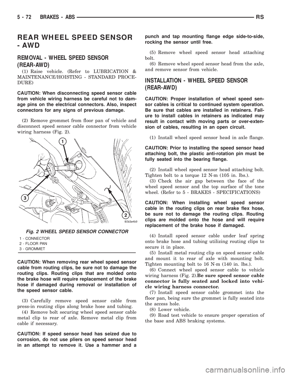
(2) Remove grommet from floor pan of vehicle and
disconnect speed sensor cable connector from vehicle
wiring harness (Fig. 2).
CAUTION: When removing rear wheel speed sensor
cable from routing clips, be sure not to damage the
routing clips. Routing clips that are molded onto
the brake hose will require replacement of the brake
hose if damaged during removal or installation of
the speed sensor cable.
(3) Carefully remove speed sensor cable from
press-in routing clips along brake hose and tubing.
(4) Remove bolt securing wheel speed sensor cable
metal clip to rear of axle. Remove metal clip from
cable if necessary.
CAUTION: If speed sensor head has seized due to
corrosion, do not use pliers on speed sensor head
in an attempt to remove it. Use a hammer and apunch and tap mounting flange edge side-to-side,
rocking the sensor until free.
(5) Remove wheel speed sensor head attaching
bolt.
(6) Remove wheel speed sensor head from the axle,
and remove sensor from vehicle.
INSTALLATION - WHEEL SPEED SENSOR
(REAR-AWD)
CAUTION: Proper installation of wheel speed sen-
sor cables is critical to continued system operation.
Be sure that cables are installed in retainers. Fail-
ure to install cables in retainers as indicated may
result in contact with moving parts or over-exten-
sion of cables, resulting in an open circuit.
(1) Install wheel speed sensor head in axle flange.
CAUTION: Prior to installing the speed sensor head
attaching bolt, the plastic anti-rotation pin must be
fully seated into the bearing flange.
(2) Install wheel speed sensor head attaching bolt.
Tighten bolt to a torque 12 N´m (105 in. lbs.).
(3) Check the air gap between the face of the
wheel speed sensor and the top surface of the tone
wheel. (Refer to 5 - BRAKES - SPECIFICATIONS)
CAUTION: When installing wheel speed sensor
cable in the routing clips on rear brake flex hose,
be sure not to damage the routing clips. Routing
clips are molded onto the hose and will require
replacement of the brake hose if damaged.
(4) Install speed sensor cable under leaf spring
onto brake hose and tubing utilizing routing clips to
secure it in place.
(5) Install metal routing clip on speed sensor cable
and mount it to rear of axle with mounting bolt.
Tighten mounting bolt to 16 N´m (140 in. lbs.).
(6) Connect wheel speed sensor cable to vehicle
wiring harness (Fig. 2).Be sure speed sensor cable
connector is fully seated and locked into vehi-
cle wiring harness connector.
(7) Install speed sensor cable grommet into the
floor pan, being sure the grommet is fully seated into
the access hole.
(8) Lower vehicle.
(9) Road test vehicle to ensure proper operation of
the base and ABS braking systems.
Fig. 2 WHEEL SPEED SENSOR CONNECTOR
1 - CONNECTOR
2 - FLOOR PAN
3 - GROMMET
5 - 72 BRAKES - ABSRS
Page 1699 of 4284
REAR WHEEL SPEED SENSOR
- FWD
REMOVAL - WHEEL SPEED SENSOR
(REAR-FWD)
(1) Raise vehicle. (Refer to LUBRICATION &
MAINTENANCE/HOISTING - STANDARD PROCE-
DURE)
CAUTION: When disconnecting speed sensor cable
from vehicle wiring harness be careful not to dam-
age pins on the electrical connectors. Also, inspect
connectors for any signs of previous damage.
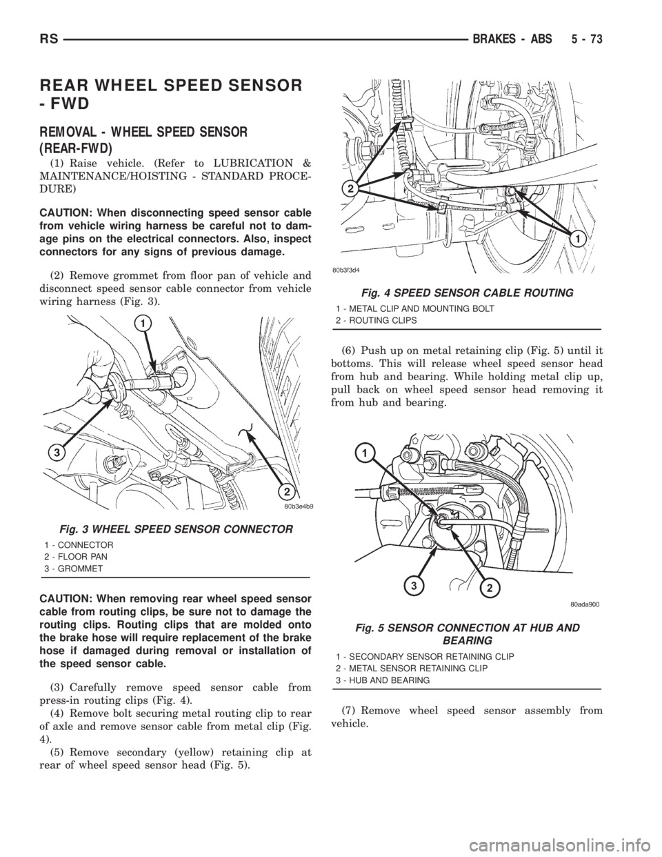
(2) Remove grommet from floor pan of vehicle and
disconnect speed sensor cable connector from vehicle
wiring harness (Fig. 3).
CAUTION: When removing rear wheel speed sensor
cable from routing clips, be sure not to damage the
routing clips. Routing clips that are molded onto
the brake hose will require replacement of the brake
hose if damaged during removal or installation of
the speed sensor cable.
(3) Carefully remove speed sensor cable from
press-in routing clips (Fig. 4).
(4) Remove bolt securing metal routing clip to rear
of axle and remove sensor cable from metal clip (Fig.
4).
(5) Remove secondary (yellow) retaining clip at
rear of wheel speed sensor head (Fig. 5).(6) Push up on metal retaining clip (Fig. 5) until it
bottoms. This will release wheel speed sensor head
from hub and bearing. While holding metal clip up,
pull back on wheel speed sensor head removing it
from hub and bearing.
(7) Remove wheel speed sensor assembly from
vehicle.
Fig. 3 WHEEL SPEED SENSOR CONNECTOR
1 - CONNECTOR
2 - FLOOR PAN
3 - GROMMET
Fig. 4 SPEED SENSOR CABLE ROUTING
1 - METAL CLIP AND MOUNTING BOLT
2 - ROUTING CLIPS
Fig. 5 SENSOR CONNECTION AT HUB AND
BEARING
1 - SECONDARY SENSOR RETAINING CLIP
2 - METAL SENSOR RETAINING CLIP
3 - HUB AND BEARING
RSBRAKES - ABS5-73
Page 1700 of 4284
INSTALLATION - WHEEL SPEED SENSOR
(REAR-FWD)
CAUTION: Proper installation of wheel speed sen-
sor cable is critical to continued system operation.
Be sure that cable is installed in routing retainers/
clips. Failure to install cable in retainers may result
in contact with moving parts or over extension of
cable, resulting in an open circuit.
NOTE: Make sure wheel speed sensor stays clean
and dry as it is installed into the hub and bearing
cap.
(1) If metal sensor retaining clip is not in the neu-
tral installed position on hub and bearing cap, install
from the bottom, if necessary, and push clip upward
until it snaps into position.
(2) Install wheel speed sensor head into rear of
hub and bearing aligning index tab with the notch in
the top of the mounting hole. Push the sensor in
until it snaps into place on the metal retaining clip.
(3) Install secondary (yellow) retaining clip over
wheel speed sensor head and engage the tabs on each
side.
(4) Route sensor cable under leaf spring along rear
of axle. Install speed sensor cable into routing clips
on rear brake flex hose (Fig. 4).
(5) Install cable into metal routing clip and attach
it to the rear axle with mounting bolt (Fig. 4).
Tighten mounting bolt to 16 N´m (140 in. lbs.).
(6) Connect wheel speed sensor cable to vehicle
wiring harness (Fig. 3).Be sure speed sensor
cable connector is fully seated and locked into
vehicle wiring harness connector.
(7) Install speed sensor cable grommet into hole in
floor pan making sure grommet is fully seated into
hole.
(8) Lower vehicle.
(9) Road test vehicle to ensure proper operation of
the base and ABS braking systems.
TONE WHEEL
INSPECTION - TONE WHEEL
NOTE: Rear tone wheels for front-wheel-drive vehi-
cles are sealed within the hub and bearing assem-
bly and cannot be inspected or replaced.
Replacement of the hub and bearing is necessary.Tone wheels can cause erratic wheel speed sensor
signals. Inspect tone wheels for the following possible
causes.
²missing, chipped, or broken teeth
²contact with the wheel speed sensor
²wheel speed sensor to tone wheel alignment
²wheel speed sensor to tone wheel clearance
²excessive tone wheel runout
²tone wheel loose on its mounting surface
If a front tone wheel is found to need replacement,
the drive shaft must be replaced. No attempt should
be made to replace just the tone wheel. (Refer to 3 -
DIFFERENTIAL & DRIVELINE/HALF SHAFT -
REMOVAL)
If a rear tone wheel is found to need replacement
on an all-wheel-drive model, the drive shaft must be
replaced. No attempt should be made to replace just
the tone wheel. (Refer to 3 - DIFFERENTIAL &
DRIVELINE/HALF SHAFT - REMOVAL)
If wheel speed sensor to tone wheel contact is evi-
dent, determine the cause and correct it before
replacing the wheel speed sensor or tone wheel.
Check the gap between the speed sensor head and
the tone wheel to ensure it is within specifications.
(Refer to 5 - BRAKES - ABS/ELECTRICAL - SPEC-
IFICATIONS)
Excessive wheel speed sensor runout can cause
erratic wheel speed sensor signals. Refer to SPECI-
FICATIONS in this section of the service manual for
the maximum allowed tone wheel runout (Refer to 5 -
BRAKES - ABS/ELECTRICAL - SPECIFICATIONS).
If tone wheel runout is excessive, determine if it is
caused by a defect in the driveshaft assembly or hub
and bearing. Replace as necessary.
Tone wheels are pressed onto their mounting sur-
faces and should not rotate independently from the
mounting surface. Replacement of the front drive-
shaft, rear driveshaft (AWD only) or rear hub and
bearing is necessary.
TRACTION CONTROL SWITCH
DIAGNOSIS AND TESTING - TRACTION
CONTROL SWITCH
(1) Remove lower column shroud.
(2) Disconnect traction control switch harness from
column harness below column.
(3) Using an ohmmeter, check for continuity read-
ing between pins. Refer to test table and (Fig. 6).
5 - 74 BRAKES - ABSRS
REAR WHEEL SPEED SENSOR - FWD (Continued)
Page 1747 of 4284
ENGINE
TABLE OF CONTENTS
page page
ENGINE
DIAGNOSIS AND TESTING.................14
COOLING SYSTEM DIAGNOSIS...........14
CLEANING..............................17
INSPECTION............................17
COOLANT
DIAGNOSIS AND TESTING.................17
COOLANT CONCENTRATION TESTING......17
STANDARD PROCEDURE..................18
COOLANT SERVICE.....................18
COOLANT RECOVERY CONTAINER
DESCRIPTION...........................18
OPERATION.............................18
DIAGNOSIS AND TESTING.................19
COOLANT RECOVERY SYSTEM CHECK.....19
REMOVAL..............................19
INSTALLATION...........................19
ENGINE BLOCK HEATER
DESCRIPTION...........................19
OPERATION.............................19
DIAGNOSIS AND TESTING.................19
ENGINE BLOCK HEATER TESTING.........19
REMOVAL..............................19
INSTALLATION...........................19
ENGINE COOLANT TEMP SENSOR - 2.4L
DESCRIPTION...........................20
REMOVAL..............................20
INSTALLATION...........................20
ENGINE COOLANT TEMP SENSOR - 3.3/3.8L
DESCRIPTION...........................20
REMOVAL..............................20
INSTALLATION...........................21
ENGINE COOLANT THERMOSTAT
DESCRIPTION...........................21
OPERATION.............................21
DIAGNOSIS AND TESTING.................22
THERMOSTAT.........................22
ENGINE COOLANT THERMOSTAT - 2.4L
REMOVAL..............................22
INSTALLATION...........................22
ENGINE COOLANT THERMOSTAT - 3.3/3.8L
REMOVAL..............................23
INSTALLATION...........................23
RADIATOR
DESCRIPTION...........................24
OPERATION.............................24
REMOVAL..............................24INSTALLATION...........................25
RADIATOR DRAINCOCK
REMOVAL..............................25
INSTALLATION...........................25
RADIATOR PRESSURE CAP
DESCRIPTION...........................26
OPERATION.............................26
DIAGNOSIS AND TESTING.................26
COOLING SYSTEM PRESSURE CAP
TESTING.............................26
RADIATOR CAP TO FILLER NECK SEAL.....26
CLEANING..............................27
INSPECTION............................27
RADIATOR FAN
DESCRIPTION...........................27
OPERATION.............................28
DIAGNOSIS AND TESTING.................28
RADIATOR FAN MOTOR TEST.............28
REMOVAL..............................29
INSTALLATION...........................29
RADIATOR FAN RELAY
DESCRIPTION...........................29
OPERATION.............................29
REMOVAL..............................29
INSTALLATION...........................29
WATER PUMP - 2.4L
DESCRIPTION...........................30
OPERATION.............................30
REMOVAL..............................30
CLEANING..............................31
INSPECTION............................31
INSTALLATION...........................31
WATER PUMP - 3.3/3.8L
DESCRIPTION...........................32
OPERATION.............................32
REMOVAL..............................32
CLEANING..............................33
INSPECTION............................33
INSTALLATION...........................33
WATER PUMP INLET TUBE - 2.4L
DESCRIPTION...........................34
REMOVAL..............................34
INSTALLATION...........................34
WATER PUMP INLET TUBE - 3.3/3.8L
REMOVAL..............................35
INSTALLATION...........................35
RSENGINE7-13
Page 1751 of 4284
CONDITION POSSIBLE CAUSES CORRECTION
COOLANT LEVEL CHANGES IN
COOLANT BOTTLE.
TEMPERATURE GAUGE IS IN
NORMAL RANGE.1. Level changes are to be
expected as coolant volume
fluctuates with engine temperature.
The coolant level will also drop as
the system removes air from a
recent filling.1. A normal condition. No repair is
necessary.
TEMPERATURE GAUGE INDICATION DIAGNOSIS CHART
CONDITION POSSIBLE CAUSES CORRECTION
TEMPERATURE GAUGE READING
IS INCONSISTENT (FLUCTUATES,
CYCLES OR IS ERRATIC).1. Normal reaction to fan and/or
thermostat cycle 1, Examples B
and C. During cold weather
operation with the heater blower in
the high position, the gauge reading
may drop slightly 1, Example D.
Fluctuation is also influenced by
outside temperature and heavy
loads 1, Example E.1. A normal condition. No correction
is necessary.
2. Gauge reading rises when
vehicle is brought to a stop after
heavy use (engine still running) 1,
Example F.2. A normal condition. No correction
is necessary. Gauge reading should
return to normal range 1, Example
A, after vehicle is driven.
3. Gauge reading high after
restarting a warmed-up (hot)
engine.3. A normal condition. No correction
is necessary. The gauge should
return to normal range 1, Example
A, after a few minutes of engine
operation.
4. Temperature gauge or engine
coolant temperature sensor
defective or shorted. Also, corroded
or loose wiring in the electrical
circuit.4. Check operation of gauge or
engine coolant temperature sensor
and repair, if necessary.
CLEANING
Drain cooling system and refill with clean water.
Refer to procedures in this section. Run engine with
radiator cap installed until upper radiator hose is
hot. Stop engine and drain water from system. If
water is dirty; fill, run, and drain system again, until
water runs clear.
INSPECTION
After performing a cleaning/flush procedure,
inspect all hoses, clamps and connections for deterio-
ration and leaks. Inspect radiator and heater core for
leaks.
COOLANT
DIAGNOSIS AND TESTING - COOLANT
CONCENTRATION
Coolant concentration should be checked when any
additional coolant was added to system or after a cool-
ant drain, flush and refill. The coolant mixture offers
optimum engine cooling and protection against corrosion
when mixed to a freeze point of -37ÉC (-34ÉF) to -59ÉC
(-50ÉF). The use of a hydrometer or a refractometer can
be used to test coolant concentration.
A hydrometer will test the amount of glycol in a
mixture by measuring the specific gravity of the mix-
ture. The higher the concentration of ethylene glycol,
the larger the number of balls that will float, and
higher the freeze protection (up to a maximum of
60% by volume glycol).
RSENGINE7-17
ENGINE (Continued)
Page 1754 of 4284
ENGINE COOLANT TEMP
SENSOR - 2.4L
DESCRIPTION
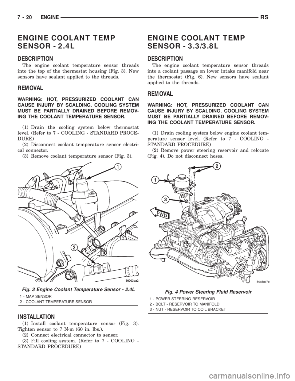
The engine coolant temperature sensor threads
into the top of the thermostat housing (Fig. 3). New
sensors have sealant applied to the threads.
REMOVAL
WARNING: HOT, PRESSURIZED COOLANT CAN
CAUSE INJURY BY SCALDING. COOLING SYSTEM
MUST BE PARTIALLY DRAINED BEFORE REMOV-
ING THE COOLANT TEMPERATURE SENSOR.
(1) Drain the cooling system below thermostat
level. (Refer to 7 - COOLING - STANDARD PROCE-
DURE)
(2) Disconnect coolant temperature sensor electri-
cal connector.
(3) Remove coolant temperature sensor (Fig. 3).
INSTALLATION
(1) Install coolant temperature sensor (Fig. 3).
Tighten sensor to 7 N´m (60 in. lbs.).
(2) Connect electrical connector to sensor.
(3) Fill cooling system. (Refer to 7 - COOLING -
STANDARD PROCEDURE)
ENGINE COOLANT TEMP
SENSOR - 3.3/3.8L
DESCRIPTION
The engine coolant temperature sensor threads
into a coolant passage on lower intake manifold near
the thermostat (Fig. 6). New sensors have sealant
applied to the threads.
REMOVAL
WARNING: HOT, PRESSURIZED COOLANT CAN
CAUSE INJURY BY SCALDING. COOLING SYSTEM
MUST BE PARTIALLY DRAINED BEFORE REMOV-
ING THE COOLANT TEMPERATURE SENSOR.
(1) Drain cooling system below engine coolant tem-
perature sensor level. (Refer to 7 - COOLING -
STANDARD PROCEDURE)
(2) Remove power steering reservoir and relocate
(Fig. 4). Do not disconnect hoses.
Fig. 3 Engine Coolant Temperature Sensor - 2.4L
1 - MAP SENSOR
2 - COOLANT TEMPERATURE SENSORFig. 4 Power Steering Fluid Reservoir
1 - POWER STEERING RESERVOIR
2 - BOLT - RESERVOIR TO MANIFOLD
3 - NUT - RESERVOIR TO COIL BRACKET
7 - 20 ENGINERS