Page 3936 of 4284
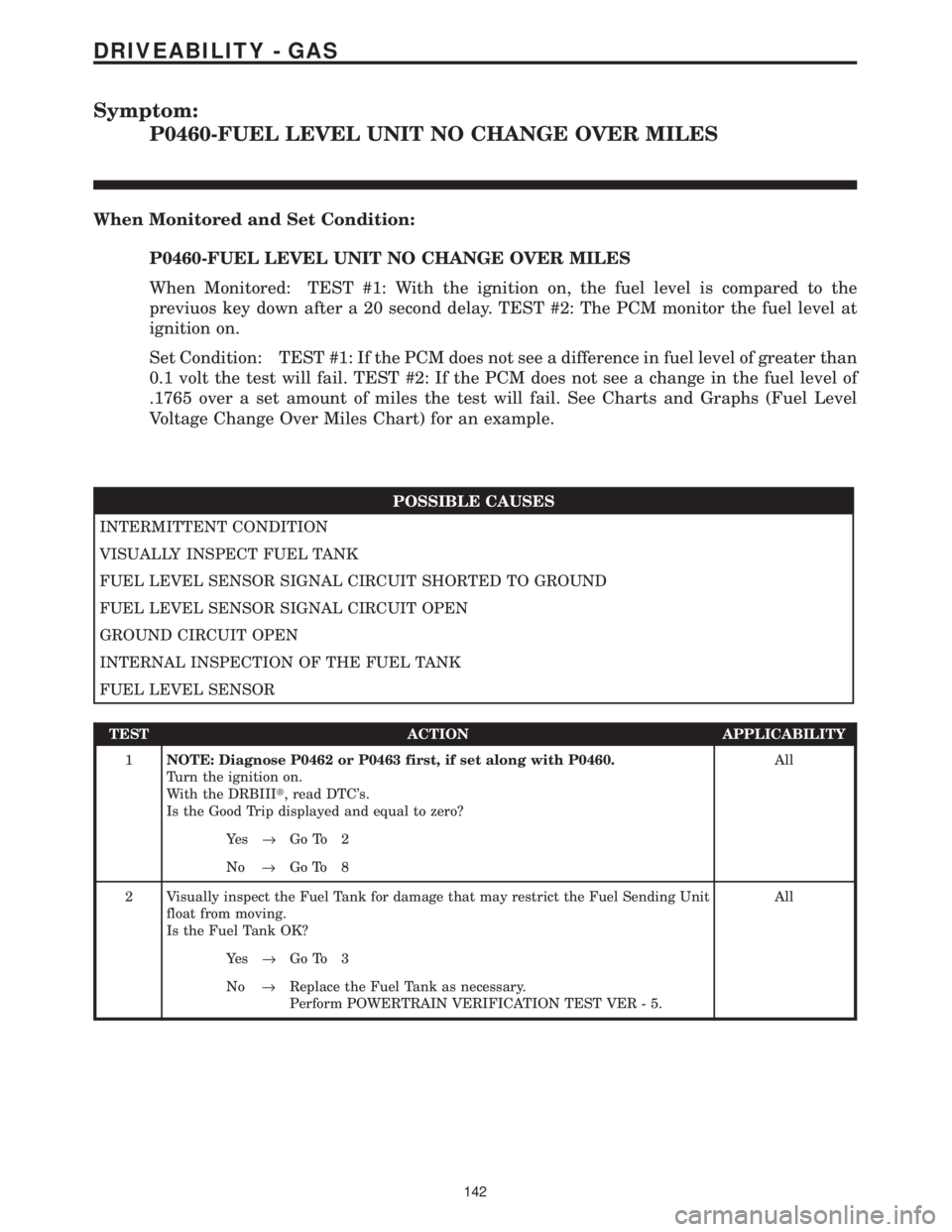
Symptom:
P0460-FUEL LEVEL UNIT NO CHANGE OVER MILES
When Monitored and Set Condition:
P0460-FUEL LEVEL UNIT NO CHANGE OVER MILES
When Monitored: TEST #1: With the ignition on, the fuel level is compared to the
previuos key down after a 20 second delay. TEST #2: The PCM monitor the fuel level at
ignition on.
Set Condition: TEST #1: If the PCM does not see a difference in fuel level of greater than
0.1 volt the test will fail. TEST #2: If the PCM does not see a change in the fuel level of
.1765 over a set amount of miles the test will fail. See Charts and Graphs (Fuel Level
Voltage Change Over Miles Chart) for an example.
POSSIBLE CAUSES
INTERMITTENT CONDITION
VISUALLY INSPECT FUEL TANK
FUEL LEVEL SENSOR SIGNAL CIRCUIT SHORTED TO GROUND
FUEL LEVEL SENSOR SIGNAL CIRCUIT OPEN
GROUND CIRCUIT OPEN
INTERNAL INSPECTION OF THE FUEL TANK
FUEL LEVEL SENSOR
TEST ACTION APPLICABILITY
1NOTE: Diagnose P0462 or P0463 first, if set along with P0460.
Turn the ignition on.
With the DRBIIIt, read DTC's.
Is the Good Trip displayed and equal to zero?All
Ye s®Go To 2
No®Go To 8
2 Visually inspect the Fuel Tank for damage that may restrict the Fuel Sending Unit
float from moving.
Is the Fuel Tank OK?All
Ye s®Go To 3
No®Replace the Fuel Tank as necessary.
Perform POWERTRAIN VERIFICATION TEST VER - 5.
142
DRIVEABILITY - GAS
Page 3974 of 4284
Symptom:
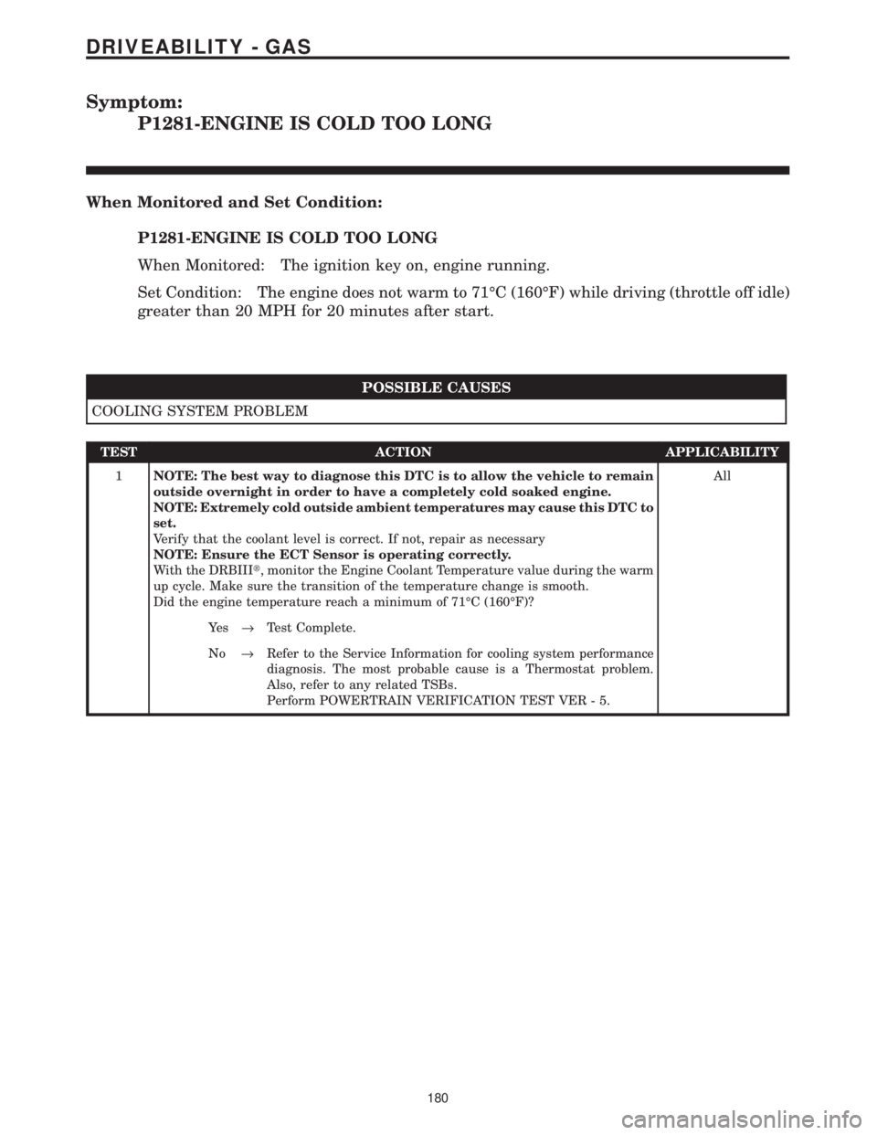
P1281-ENGINE IS COLD TOO LONG
When Monitored and Set Condition:
P1281-ENGINE IS COLD TOO LONG
When Monitored: The ignition key on, engine running.
Set Condition: The engine does not warm to 71ÉC (160ÉF) while driving (throttle off idle)
greater than 20 MPH for 20 minutes after start.
POSSIBLE CAUSES
COOLING SYSTEM PROBLEM
TEST ACTION APPLICABILITY
1NOTE: The best way to diagnose this DTC is to allow the vehicle to remain
outside overnight in order to have a completely cold soaked engine.
NOTE: Extremely cold outside ambient temperatures may cause this DTC to
set.
Verify that the coolant level is correct. If not, repair as necessary
NOTE: Ensure the ECT Sensor is operating correctly.
With the DRBIIIt, monitor the Engine Coolant Temperature value during the warm
up cycle. Make sure the transition of the temperature change is smooth.
Did the engine temperature reach a minimum of 71ÉC (160ÉF)?All
Ye s®Test Complete.
No®Refer to the Service Information for cooling system performance
diagnosis. The most probable cause is a Thermostat problem.
Also, refer to any related TSBs.
Perform POWERTRAIN VERIFICATION TEST VER - 5.
180
DRIVEABILITY - GAS
Page 3992 of 4284
Symptom:
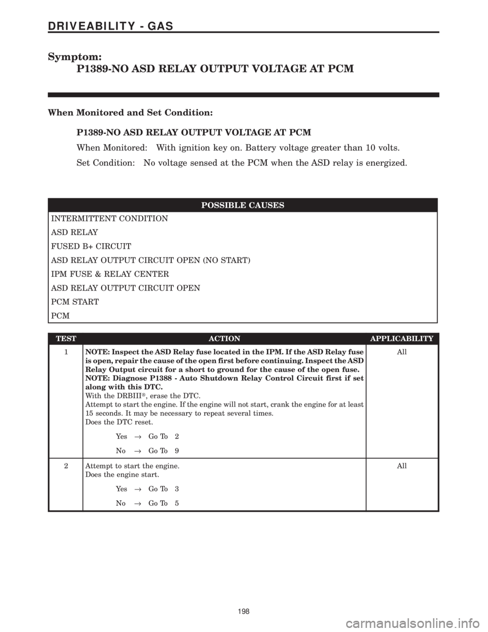
P1389-NO ASD RELAY OUTPUT VOLTAGE AT PCM
When Monitored and Set Condition:
P1389-NO ASD RELAY OUTPUT VOLTAGE AT PCM
When Monitored: With ignition key on. Battery voltage greater than 10 volts.
Set Condition: No voltage sensed at the PCM when the ASD relay is energized.
POSSIBLE CAUSES
INTERMITTENT CONDITION
ASD RELAY
FUSED B+ CIRCUIT
ASD RELAY OUTPUT CIRCUIT OPEN (NO START)
IPM FUSE & RELAY CENTER
ASD RELAY OUTPUT CIRCUIT OPEN
PCM START
PCM
TEST ACTION APPLICABILITY
1NOTE: Inspect the ASD Relay fuse located in the IPM. If the ASD Relay fuse
is open, repair the cause of the open first before continuing. Inspect the ASD
Relay Output circuit for a short to ground for the cause of the open fuse.
NOTE: Diagnose P1388 - Auto Shutdown Relay Control Circuit first if set
along with this DTC.
With the DRBIIIt, erase the DTC.
Attempt to start the engine. If the engine will not start, crank the engine for at least
15 seconds. It may be necessary to repeat several times.
Does the DTC reset.All
Ye s®Go To 2
No®Go To 9
2 Attempt to start the engine.
Does the engine start.All
Ye s®Go To 3
No®Go To 5
198
DRIVEABILITY - GAS
Page 4015 of 4284
Symptom:
P1602-PCM NOT PROGRAMMED
When Monitored and Set Condition:
P1602-PCM NOT PROGRAMMED
When Monitored: Ignition key on.
Set Condition: PCM has not been programmed.
POSSIBLE CAUSES
PCM PROGRAMMED
TEST ACTION APPLICABILITY
1 Attempt to program PCM in accordance with the Service Information.
Turn the ignition on.
Start the engine.
NOTE: If the engine will not start, crank the engine over for 15 seconds.
Crank at least 2 time with the ignition switch returning to the off position
each time.
Allow the engine to reach normal operating temperature.
With the DRBIIIt, read DTCs.
Does the DTC reset?All
Ye s®Replace and program the Powertrain Control Module in accor-
dance with the Service Information.
Perform POWERTRAIN VERIFICATION TEST VER-1.
No®Test Complete.
221
DRIVEABILITY - GAS
Page 4042 of 4284
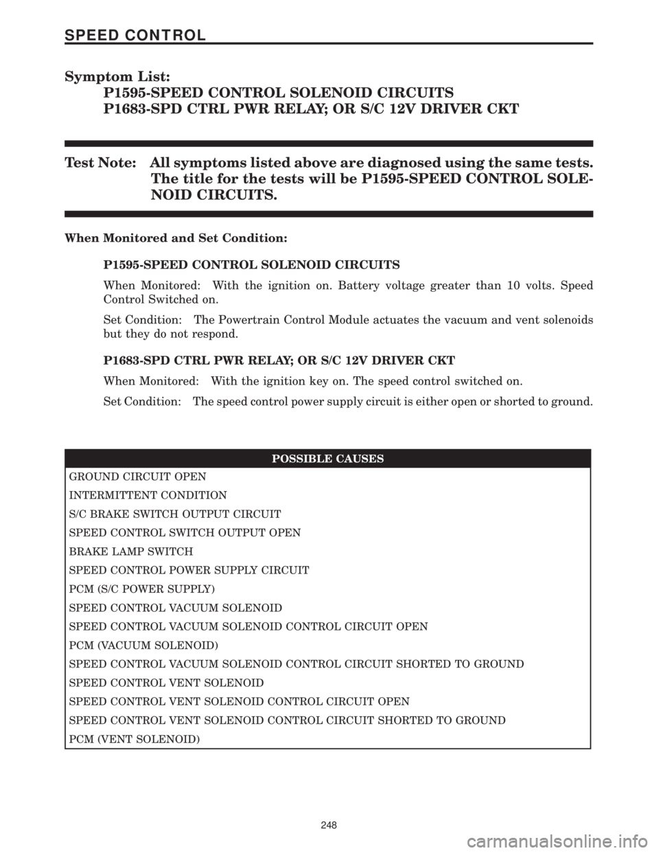
Symptom List:
P1595-SPEED CONTROL SOLENOID CIRCUITS
P1683-SPD CTRL PWR RELAY; OR S/C 12V DRIVER CKT
Test Note: All symptoms listed above are diagnosed using the same tests.
The title for the tests will be P1595-SPEED CONTROL SOLE-
NOID CIRCUITS.
When Monitored and Set Condition:
P1595-SPEED CONTROL SOLENOID CIRCUITS
When Monitored: With the ignition on. Battery voltage greater than 10 volts. Speed
Control Switched on.
Set Condition: The Powertrain Control Module actuates the vacuum and vent solenoids
but they do not respond.
P1683-SPD CTRL PWR RELAY; OR S/C 12V DRIVER CKT
When Monitored: With the ignition key on. The speed control switched on.
Set Condition: The speed control power supply circuit is either open or shorted to ground.
POSSIBLE CAUSES
GROUND CIRCUIT OPEN
INTERMITTENT CONDITION
S/C BRAKE SWITCH OUTPUT CIRCUIT
SPEED CONTROL SWITCH OUTPUT OPEN
BRAKE LAMP SWITCH
SPEED CONTROL POWER SUPPLY CIRCUIT
PCM (S/C POWER SUPPLY)
SPEED CONTROL VACUUM SOLENOID
SPEED CONTROL VACUUM SOLENOID CONTROL CIRCUIT OPEN
PCM (VACUUM SOLENOID)
SPEED CONTROL VACUUM SOLENOID CONTROL CIRCUIT SHORTED TO GROUND
SPEED CONTROL VENT SOLENOID
SPEED CONTROL VENT SOLENOID CONTROL CIRCUIT OPEN
SPEED CONTROL VENT SOLENOID CONTROL CIRCUIT SHORTED TO GROUND
PCM (VENT SOLENOID)
248
SPEED CONTROL
Page 4047 of 4284
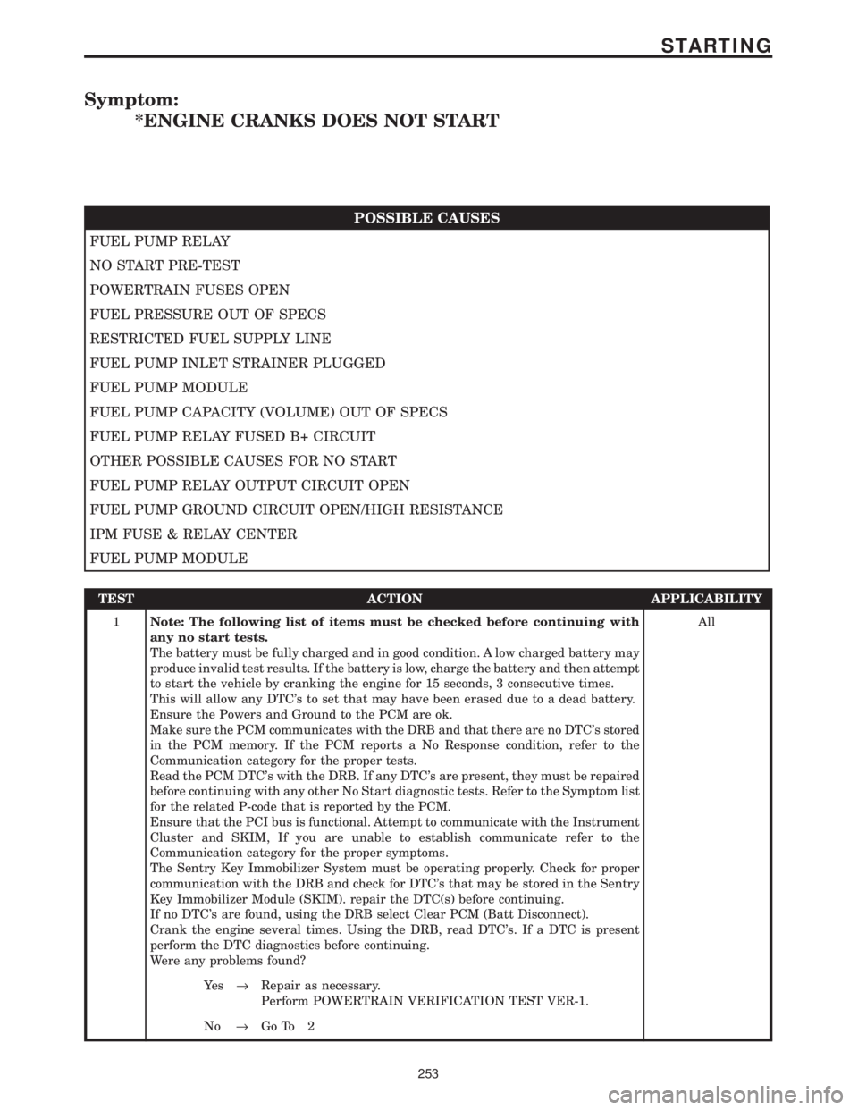
Symptom:
*ENGINE CRANKS DOES NOT START
POSSIBLE CAUSES
FUEL PUMP RELAY
NO START PRE-TEST
POWERTRAIN FUSES OPEN
FUEL PRESSURE OUT OF SPECS
RESTRICTED FUEL SUPPLY LINE
FUEL PUMP INLET STRAINER PLUGGED
FUEL PUMP MODULE
FUEL PUMP CAPACITY (VOLUME) OUT OF SPECS
FUEL PUMP RELAY FUSED B+ CIRCUIT
OTHER POSSIBLE CAUSES FOR NO START
FUEL PUMP RELAY OUTPUT CIRCUIT OPEN
FUEL PUMP GROUND CIRCUIT OPEN/HIGH RESISTANCE
IPM FUSE & RELAY CENTER
FUEL PUMP MODULE
TEST ACTION APPLICABILITY
1Note: The following list of items must be checked before continuing with
any no start tests.
The battery must be fully charged and in good condition. A low charged battery may
produce invalid test results. If the battery is low, charge the battery and then attempt
to start the vehicle by cranking the engine for 15 seconds, 3 consecutive times.
This will allow any DTC's to set that may have been erased due to a dead battery.
Ensure the Powers and Ground to the PCM are ok.
Make sure the PCM communicates with the DRB and that there are no DTC's stored
in the PCM memory. If the PCM reports a No Response condition, refer to the
Communication category for the proper tests.
Read the PCM DTC's with the DRB. If any DTC's are present, they must be repaired
before continuing with any other No Start diagnostic tests. Refer to the Symptom list
for the related P-code that is reported by the PCM.
Ensure that the PCI bus is functional. Attempt to communicate with the Instrument
Cluster and SKIM, If you are unable to establish communicate refer to the
Communication category for the proper symptoms.
The Sentry Key Immobilizer System must be operating properly. Check for proper
communication with the DRB and check for DTC's that may be stored in the Sentry
Key Immobilizer Module (SKIM). repair the DTC(s) before continuing.
If no DTC's are found, using the DRB select Clear PCM (Batt Disconnect).
Crank the engine several times. Using the DRB, read DTC's. If a DTC is present
perform the DTC diagnostics before continuing.
Were any problems found?All
Ye s®Repair as necessary.
Perform POWERTRAIN VERIFICATION TEST VER-1.
No®Go To 2
253
STARTING
Page 4053 of 4284

TEST ACTION APPLICABILITY
4 Turn ignition off.
Remove the Starter Relay from PDC.
WARNING: The Parking Brake must be on and the Transmission must be in
park for a vehicle equipped with an automatic transmission.
Warning: The engine may be cranked in the next step. Keep away from
moving engine parts.
Briefly connect a jumper wire between Starter Relay B+ circuit and the Starter Relay
Output Circuits.
Did the Starter Motor crank the engine?All
Ye s®Go To 5
No®Go To 8
5 Turn the ignition off.
Remove the Starter Relay from the PDC.
Turn the ignition on.
Using a 12-volt test light, probe the Ignition Switch Output circuit in the Starter
Relay connector.
While observing 12-volt test light, hold ignition key in the start position.
Does the test light illuminate brightly?All
Ye s®Go To 6
No®Repair the Ignition Switch Output circuit for an open or high
resistance.
Perform POWERTRAIN VERIFICATION TEST VER-1.
6 Turn the ignition off.
Remove the Starter Relay from the PDC.
Disconnect the PCM harness connector.
Measure the Starter Relay Control circuit between the Relay terminal and the PCM
harness connector.
Is the resistance below 5.0 ohms?All
Ye s®Go To 7
No®Repair the Starter Relay Control circuit for an open.
Perform POWERTRAIN VERIFICATION TEST VER-1.
7 Turn the ignition off.
Install a substitute a Relay in the of the Starter Motor Relay.
Attempt to start the vehicle.
Does the engine crank over?All
Ye s®Replace the Starter Motor Relay.
Perform POWERTRAIN VERIFICATION TEST VER-1.
No®Replace and program the Powertrain Control Module in accor-
dance with the Service Information.
Perform POWERTRAIN VERIFICATION TEST VER-1.
259
STARTING
*NO CRANK CONDITION ÐContinued
Page 4061 of 4284
POSSIBLE CAUSES
SKIM INTERNAL DTC FAILURE
TEST ACTION APPLICABILITY
1Note: This trouble code indicates an internal SKIM fault.
With the DRB III, read and record the SKIM DTCs and then erase the SKIM DTCs
Perform 10 ignition key cycles, leaving the ignition key on for a minimum of 90
seconds per cycle.
With the DRB III, read the SKIM DTCs.
Did the same SKIM DTC return?All
Ye s®Replace and program the Sentry Key Immobilizer Module in
accordance with the Service Information.
Perform SKIS VERIFICATION TEST.
No®Test Complete.
267
VEHICLE THEFT/SECURITY
ANTENNA FAILURE ÐContinued