2001 CHRYSLER VOYAGER key
[x] Cancel search: keyPage 3753 of 4284
²Vehicle Speed Sensor
²Engine Coolant Temperature Sensor
²Throttle Position Sensor
²Engine Controller Self Test Faults
²Cam or Crank Sensor
²Injector and Coil
²Idle Air Control Motor
²EVAP Electrical
²EGR Solenoid Electrical
²Intake Air Temperature
²5 Volt Feed
ConflictÐThe Task Manager does not run the
Oxygen Sensor Monitor if any of the following condi-
tions are present:
²A/C ON (A/C clutch cycling temporarily sus-
pends monitor)
²Purge flow in progress
²Ethanel content learn is takeng place and the
ethenal used once flag is set
SuspendÐThe Task Manager suspends maturing
a fault for the Oxygen Sensor Monitor if an of the fol-
lowing are present:
²Oxygen Sensor Heater Monitor, Priority 1
²Misfire Monitor, Priority 2
OXYGEN SENSOR HEATER MONITOR
DESCRIPTIONÐIf there is an oxygen sensor
(O2S) DTC as well as a O2S heater DTC, the O2S
fault MUST be repaired first. After the O2S fault is
repaired, verify that the heater circuit is operating
correctly.
The voltage readings taken from the O2S are very
temperature sensitive. The readings are not accurate
below 300ÉC. Heating of the O2S is done to allow the
engine controller to shift to closed loop control as
soon as possible. The heating element used to heat
the O2S must be tested to ensure that it is heating
the sensor properly.
The heater element itself is not tested. The sensor
output is used to test the heater by isolating the
effect of the heater element on the O2S output volt-
age from the other effects. The resistance is normally
between 100 ohms and 4.5 megaohms. When oxygen
sensor temperature increases, the resistance in the
internal circuit decreases. The PCM sends a 5 volts
biased signal through the oxygen sensors to ground
this monitoring circuit. As the temperature increases,
resistance decreases and the PCM detects a lower
voltage at the reference signal. Inversely, as the tem-
perature decreases, the resistance increases and the
PCM detects a higher voltage at the reference signal.
The O2S circuit is monitored for a drop in voltage.
OPERATIONÐThe Oxygen Sensor Heater Moni-
tor begins after the ignition has been turned OFF
and the O2 sensors have cooled. The PCM sends a 5
volt bias to the oxygen sensor every 1.6 seconds. ThePCM keeps it biased for 35 ms each time. As the sen-
sor cools down, the resistance increases and the PCM
reads the increase in voltage. Once voltage has
increased to a predetermined amount, higher than
when the test started, the oxygen sensor is cool
enough to test heater operation.
When the oxygen sensor is cool enough, the PCM
energizes the ASD relay. Voltage to the O2 sensor
begins to increase the temperature. As the sensor
temperature increases, the internal resistance
decreases. The PCM continues biasing the 5 volt sig-
nal to the sensor. Each time the signal is biased, the
PCM reads a voltage decrease. When the PCM
detects a voltage decrease of a predetermined value
for several biased pulses, the test passes.
The heater elements are tested each time the
engine is turned OFF if all the enabling conditions
are met. If the monitor fails, the PCM stores a
maturing fault and a Freeze Frame is entered. If two
consecutive tests fail, a DTC is stored. Because the
ignition is OFF, the MIL is illuminated at the begin-
ning of the next key cycle.
Enabling ConditionsÐThe following conditions
must be met for the PCM to run the oxygen sensor
heater test:
²Engine run time of at least 5.1 minutes
²Key OFF power down
²Battery voltage of at least 10 volts
²Sufficient Oxygen Sensor cool down
Pending ConditionsÐThere are not conditions or
situations that prompt conflict or suspension of test-
ing. The oxygen sensor heater test is not run pending
resolution of MIL illumination due to oxygen sensor
failure.
SuspendÐThere are no conditions which exist for
suspending the Heater Monitor.
CATALYST MONITOR
To comply with clean air regulations, vehicles are
equipped with catalytic converters. These converters
reduce the emission of hydrocarbons, oxides of nitro-
gen and carbon monoxide.
Normal vehicle miles or engine misfire can cause a
catalyst to decay. A meltdown of the ceramic core can
cause a reduction of the exhaust passage. This can
increase vehicle emissions and deteriorate engine
performance, driveability and fuel economy.
The catalyst monitor uses dual oxygen sensors
(O2S's) to monitor the efficiency of the converter. The
dual O2S strategy is based on the fact that as a cat-
alyst deteriorates, its oxygen storage capacity and its
efficiency are both reduced. By monitoring the oxy-
gen storage capacity of a catalyst, its efficiency can
be indirectly calculated. The upstream O2S is used to
detect the amount of oxygen in the exhaust gas
before the gas enters the catalytic converter. The
RSEMISSIONS CONTROL25-3
EMISSIONS CONTROL (Continued)
Page 3774 of 4284
The Task Manager Screen shows both a Requested
MIL state and an Actual MIL state. When the MIL is
illuminated upon completion of a test for a third trip,
the Requested MIL state changes to OFF. However,
the MIL remains illuminated until the next key
cycle. (On some vehicles, the MIL will actually turn
OFF during the third key cycle) During the key cycle
for the third good trip, the Requested MIL state is
OFF, while the Actual MILL state is ON. After the
next key cycle, the MIL is not illuminated and both
MIL states read OFF.
Diagnostic Trouble Codes (DTCs)
With OBD II, different DTC faults have different
priorities according to regulations. As a result, the
priorities determine MIL illumination and DTC era-
sure. DTCs are entered according to individual prior-
ity. DTCs with a higher priority overwrite lower
priority DTCs.
Priorities
²Priority 0 ÐNon-emissions related trouble codes
²Priority 1 Ð One trip failure of a two trip fault
for non-fuel system and non-misfire.
²Priority 2 Ð One trip failure of a two trip fault
for fuel system (rich/lean) or misfire.
²Priority3ÐTwotrip failure for a non-fuel sys-
tem and non-misfire or matured one trip comprehen-
sive component fault.
²Priority4ÐTwotrip failure or matured fault
for fuel system (rich/lean) and misfire or one trip cat-
alyst damaging misfire.
Non-emissions related failures have no priority.
One trip failures of two trip faults have low priority.
Two trip failures or matured faults have higher pri-
ority. One and two trip failures of fuel system and
misfire monitor take precedence over non-fuel system
and non-misfire failures.
DTC Self Erasure
With one trip components or systems, the MIL is
illuminated upon test failure and DTCs are stored.
Two trip monitors are components requiring failure
in two consecutive trips for MIL illumination. Upon
failure of the first test, the Task Manager enters a
maturing code. If the component fails the test for a
second time the code matures and a DTC is set.
After three good trips the MIL is extinguished and
the Task Manager automatically switches the trip
counter to a warm-up cycle counter. DTCs are auto-
matically erased following 40 warm-up cycles if the
component does not fail again.
For misfire and fuel system monitors, the compo-
nent must pass the test under a Similar Conditions
Window in order to record a good trip. A Similar Con-
ditions Window is when engine RPM is within6375RPM and load is within610% of when the fault
occurred.
NOTE: It is important to understand that a compo-
nent does not have to fail under a similar window of
operation to mature. It must pass the test under a
Similar Conditions Window when it failed to record
a Good Trip for DTC erasure for misfire and fuel
system monitors.
DTCs can be erased anytime with a DRBIIIt.
Erasing the DTC with the DRBIIIterases all OBD II
information. The DRBIIItautomatically displays a
warning that erasing the DTC will also erase all
OBD II monitor data. This includes all counter infor-
mation for warm-up cycles, trips and Freeze Frame.
Trip Indicator
TheTripis essential for running monitors and
extinguishing the MIL. In OBD II terms, a trip is a
set of vehicle operating conditions that must be met
for a specific monitor to run. All trips begin with a
key cycle.
Good Trip
The Good Trip counters are as follows:
²Global Good Trip
²Fuel System Good Trip
²Misfire Good Trip
²Alternate Good Trip (appears as a Global Good
Trip on DRBIIIt)
²Comprehensive Components
²Major Monitor
²Warm-Up Cycles
Global Good Trip
To increment a Global Good Trip, the Oxygen sen-
sor and Catalyst efficiency monitors must have run
and passed.
Fuel System Good Trip
To count a good trip (three required) and turn off
the MIL, the following conditions must occur:
²Engine in closed loop
²Operating in Similar Conditions Window
²Short Term multiplied by Long Term less than
threshold
²Less than threshold for a predetermined time
If all of the previous criteria are met, the PCM will
count a good trip (three required) and turn off the
MIL.
Misfire Good Trip
If the following conditions are met the PCM will
count one good trip (three required) in order to turn
off the MIL:
²Operating in Similar Condition Window
²1000 engine revolutions with no misfire
Alternate Good Trip
Alternate Good Trips are used in place of Global
Good Trips for Comprehensive Components and
25 - 24 ON-BOARD DIAGNOSTICSRS
TASK MANAGER (Continued)
Page 3777 of 4284
EMISSIONS CONTROL 2.5L TURBO DIESEL
TABLE OF CONTENTS
page page
EMISSIONS CONTROL 2.5L TURBO DIESEL
DESCRIPTION............................1
SPECIFICATIONS.........................2EXHAUST GAS RECIRCULATION.............3
ON-BOARD DIAGNOSTICS..................6
EMISSIONS CONTROL 2.5L
TURBO DIESEL
DESCRIPTION
The 2.5L diesel Engine Control Module (ECM) con-
trols many different circuits in the fuel injection
pump and engine systems. If the ECM senses a prob-
lem with a monitored circuit that indicates an actual
problem, a Diagnostic Trouble Code (DTC) will be
stored in the ECM's memory, and eventually may
illuminate the MIL (Malfunction Indicator Lamp)
constantly while the key is on. If the problem is
repaired, or is intermittent, the ECM will erase the
DTC after 40 warm-up cycles without the the fault
detected. A warm-up cycle consists of starting the
vehicle when the engine is cold, then the engine is
warmed up to a certain temperature, and finally, the
engine temperature falls to a normal operating tem-
perature, then the key is turned off.
Certain criteria must be met for a DTC to be
entered into ECM memory. The criteria may be a
specific range of engine rpm, engine or fuel tempera-
ture and/or input voltage to the ECM. A DTC indi-
cates that the ECM has identified an abnormal
signal in a circuit or the system.
There are several operating conditions that the
ECM does not monitor and set a DTC for. Refer to
the following Monitored Circuits and Non±Monitored
Circuits in this section.
ECM MONITORED SYSTEMS
The ECM can detect certain problems in the elec-
trical system.
Open or Shorted Circuit± The ECM will not
distinguish between an open or a short to ground,
however the ECM can determine if there is excessive
current on a circuit, such as a short to voltage or a
decrease in component resistance.
Output Device Current Flow± The ECM senses
whether the output devices are electrically connected.
If there is a problem with the circuit, the ECM
senses whether the circuit is open, shorted to ground
(±), or shorted to (+) voltage.Fuel Pressure:Fuel pressure is controlled by the
fuel injection pump and fuel pressure solenoid. The
ECM uses a fuel pressure sensor to determine if a
fuel pressure problem exists.
Fuel Injector Malfunctions:The ECM can deter-
mine if a fuel injector has an electrical problem. The
fuel injectors on the diesel engine arecontrolledby
the ECM.
ECM NON±MONITORED SYSTEMS
The ECM does not monitor the following circuits,
systems or conditions that could have malfunctions
that result in driveability problems. A DTC will not
be displayed for these conditions.
Cylinder Compression:The ECM cannot detect
uneven, low, or high engine cylinder compression.
Exhaust System:The ECM cannot detect a
plugged, restricted or leaking exhaust system.
Vacuum Assist:Leaks or restrictions in the vac-
uum circuits of the Exhaust Gas Recirculation Sys-
tem (EGR) are not monitored by the ECM.
ECM System Ground:The ECM cannot deter-
mine a poor system ground. However, a DTC may be
generated as a result of this condition.
ECM/PCM Connector Engagement:The ECM
cannot determine spread or damaged connector pins.
However, a DTC may be generated as a result of this
condition.
HIGH AND LOW LIMITS
The ECM compares input signals from each input
device. It has high and low limits that are pro-
grammed into it for that device. If the inputs are not
within specifications and other DTC criteria are met,
a DTC will be stored in memory. Other DTC criteria
might include engine rpm limits or input voltages
from other sensors or switches. The other inputs
might have to be sensed by the ECM when it senses
a high or low input voltage from the control system
device in question.
RGEMISSIONS CONTROL 2.5L TURBO DIESEL25a-1
Page 3785 of 4284
Generic Scan Tool Code DRB IIITScan Tool Display
P0685 ECM/PCM Relay Control Circuit Shuts Off Too Early
ECM/PCM Relay Control Circuit Shuts Off Too Late
P0703 Brake Switch Signal Circuits Incorrect Can Message
Brake Switch Signal Circuits Plausibility With Redundant Contact
P1130 Fuel Rail Pressure Malfunction Small Leakage Detected
Fuel Rail Pressure Malfunction Small Leakage Detected
P1131 Fuel Pressure Solenoid Open Circuit
Fuel Pressure Solenoid Short Circuit
P1206 Calculated Injector Voltage #1 Too Low
Calculated Injector Voltage #2 Too Low
P1511 Battery Sense Line 1 Voltage Too High
Battery Sense Line 1 Voltage Too Low
P1601 Capacitor Voltage 1 Voltage Too High
Capacitor Voltage 1 Voltage Too Low
P1602 Capacitor Voltage 2 Voltage Too High
Capacitor Voltage 2 Voltage Too Low
P1605 Ignition Switch Plausibility
P1610 Voltage Regulator Signal Voltage Too High
Voltage Regulator Signal Voltage Too Low
P1680 EEPROM Plausibility Checksum Error
EEPROM Plausibility Code Word Incorrect Or Missing
EEPROM Plausibility Communication Error
EEPROM Plausibility Variation Number Error
EEPROM Plausibility VIN Checksum Error
EEPROM Plausibility VIN Write Error
P1685 SKIM System Invalid Key Code Received
SKIM System Invalid Secret Key In EEPROM
SKIM System Key Communication Timed Out
SKIM System SKIM Error
SKIM System Write Access To EEPROM Failure
P1696 EEPROM Communication Error
EEPROM Communication Not Verified
EEPROM Quanity Stop
EEPROM Recovery Occured
EEPROM Redundant Overrun Monitoring
RGON-BOARD DIAGNOSTICS25a-9
ON-BOARD DIAGNOSTICS (Continued)
Page 3789 of 4284
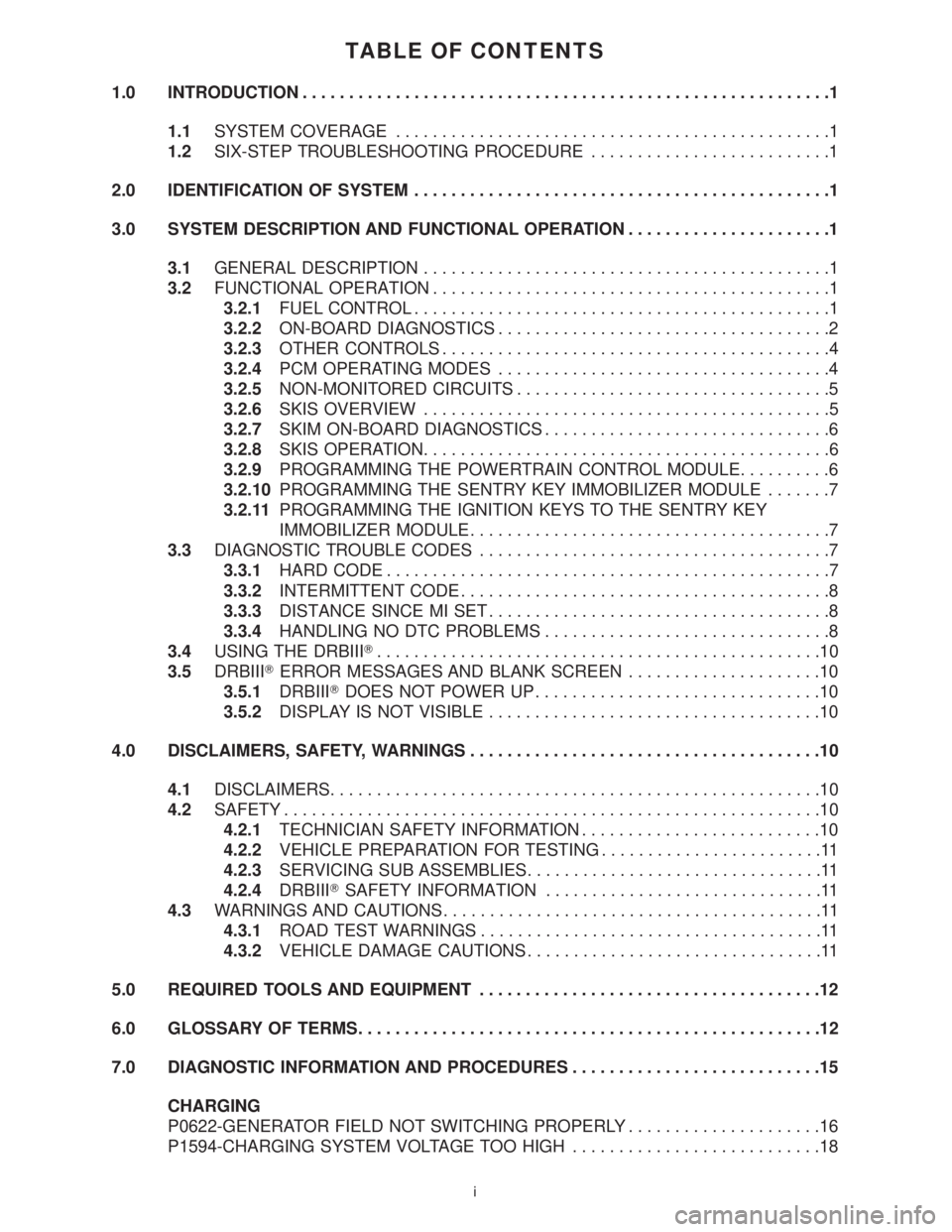
TABLE OF CONTENTS
1.0 INTRODUCTION.........................................................1
1.1SYSTEM COVERAGE...............................................1
1.2SIX-STEP TROUBLESHOOTING PROCEDURE..........................1
2.0 IDENTIFICATION OF SYSTEM.............................................1
3.0 SYSTEM DESCRIPTION AND FUNCTIONAL OPERATION......................1
3.1GENERAL DESCRIPTION............................................1
3.2FUNCTIONAL OPERATION...........................................1
3.2.1FUEL CONTROL.............................................1
3.2.2ON-BOARD DIAGNOSTICS....................................2
3.2.3OTHER CONTROLS..........................................4
3.2.4PCM OPERATING MODES....................................4
3.2.5NON-MONITORED CIRCUITS..................................5
3.2.6SKIS OVERVIEW............................................5
3.2.7SKIM ON-BOARD DIAGNOSTICS...............................6
3.2.8SKIS OPERATION............................................6
3.2.9PROGRAMMING THE POWERTRAIN CONTROL MODULE..........6
3.2.10PROGRAMMING THE SENTRY KEY IMMOBILIZER MODULE.......7
3.2.11PROGRAMMING THE IGNITION KEYS TO THE SENTRY KEY
IMMOBILIZER MODULE.......................................7
3.3DIAGNOSTIC TROUBLE CODES......................................7
3.3.1HARD CODE................................................7
3.3.2INTERMITTENT CODE........................................8
3.3.3DISTANCE SINCE MI SET.....................................8
3.3.4HANDLING NO DTC PROBLEMS...............................8
3.4USING THE DRBIIIT................................................10
3.5DRBIIITERROR MESSAGES AND BLANK SCREEN.....................10
3.5.1DRBIIITDOES NOT POWER UP...............................10
3.5.2DISPLAY IS NOT VISIBLE....................................10
4.0 DISCLAIMERS, SAFETY, WARNINGS......................................10
4.1DISCLAIMERS.....................................................10
4.2SAFETY..........................................................10
4.2.1TECHNICIAN SAFETY INFORMATION..........................10
4.2.2VEHICLE PREPARATION FOR TESTING........................11
4.2.3SERVICING SUB ASSEMBLIES................................11
4.2.4DRBIIITSAFETY INFORMATION..............................11
4.3WARNINGS AND CAUTIONS.........................................11
4.3.1ROAD TEST WARNINGS.....................................11
4.3.2VEHICLE DAMAGE CAUTIONS................................11
5.0 REQUIRED TOOLS AND EQUIPMENT.....................................12
6.0 GLOSSARY OF TERMS..................................................12
7.0 DIAGNOSTIC INFORMATION AND PROCEDURES...........................15
CHARGING
P0622-GENERATOR FIELD NOT SWITCHING PROPERLY.....................16
P1594-CHARGING SYSTEM VOLTAGE TOO HIGH...........................18
i
Page 3790 of 4284
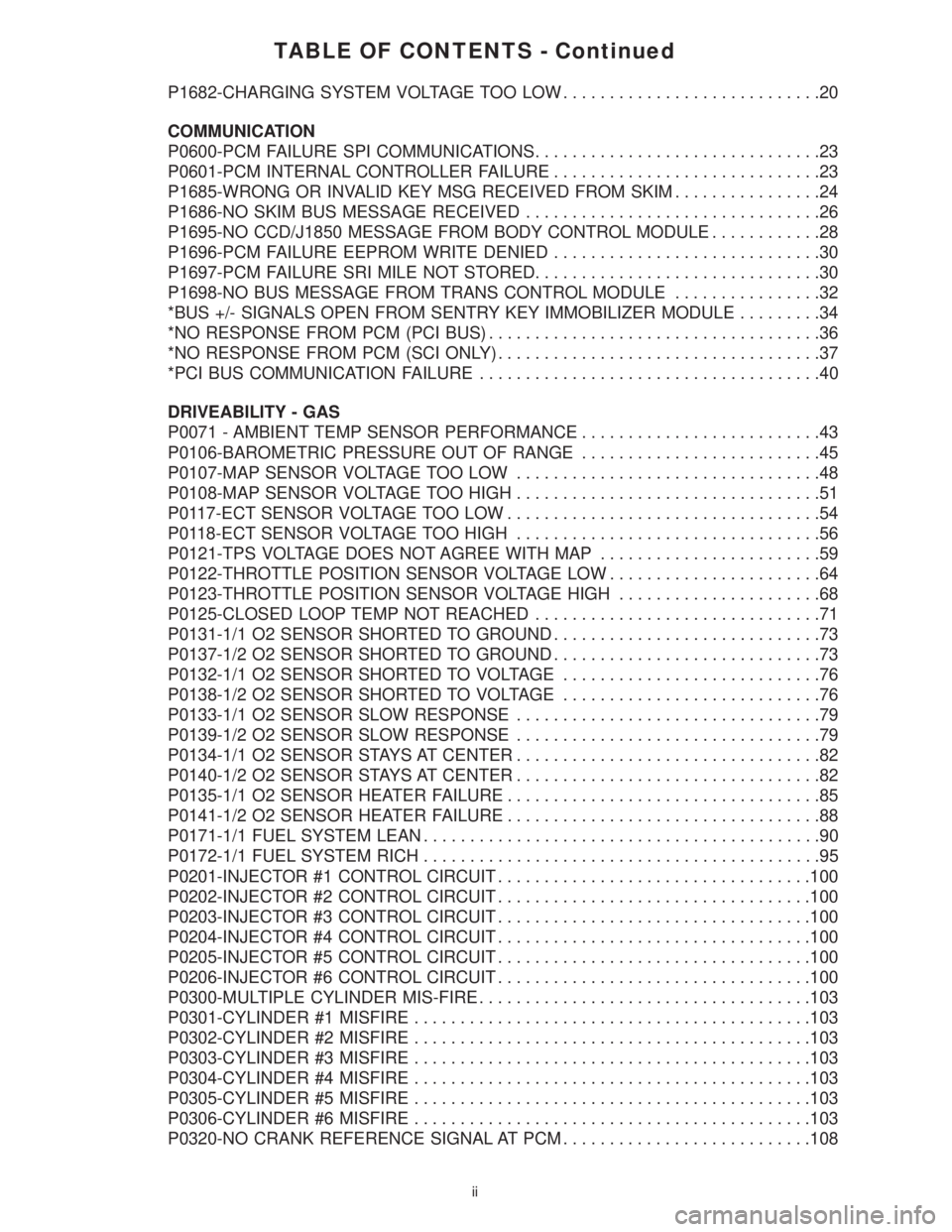
TABLE OF CONTENTS - Continued
P1682-CHARGING SYSTEM VOLTAGE TOO LOW............................20
COMMUNICATION
P0600-PCM FAILURE SPI COMMUNICATIONS...............................23
P0601-PCM INTERNAL CONTROLLER FAILURE.............................23
P1685-WRONG OR INVALID KEY MSG RECEIVED FROM SKIM................24
P1686-NO SKIM BUS MESSAGE RECEIVED................................26
P1695-NO CCD/J1850 MESSAGE FROM BODY CONTROL MODULE............28
P1696-PCM FAILURE EEPROM WRITE DENIED.............................30
P1697-PCM FAILURE SRI MILE NOT STORED...............................30
P1698-NO BUS MESSAGE FROM TRANS CONTROL MODULE................32
*BUS +/- SIGNALS OPEN FROM SENTRY KEY IMMOBILIZER MODULE.........34
*NO RESPONSE FROM PCM (PCI BUS)....................................36
*NO RESPONSE FROM PCM (SCI ONLY)...................................37
*PCI BUS COMMUNICATION FAILURE.....................................40
DRIVEABILITY - GAS
P0071 - AMBIENT TEMP SENSOR PERFORMANCE..........................43
P0106-BAROMETRIC PRESSURE OUT OF RANGE..........................45
P0107-MAP SENSOR VOLTAGE TOO LOW.................................48
P0108-MAP SENSOR VOLTAGE TOO HIGH.................................51
P0117-ECT SENSOR VOLTAGE TOO LOW..................................54
P0118-ECT SENSOR VOLTAGE TOO HIGH.................................56
P0121-TPS VOLTAGE DOES NOT AGREE WITH MAP........................59
P0122-THROTTLE POSITION SENSOR VOLTAGE LOW.......................64
P0123-THROTTLE POSITION SENSOR VOLTAGE HIGH......................68
P0125-CLOSED LOOP TEMP NOT REACHED...............................71
P0131-1/1 O2 SENSOR SHORTED TO GROUND.............................73
P0137-1/2 O2 SENSOR SHORTED TO GROUND.............................73
P0132-1/1 O2 SENSOR SHORTED TO VOLTAGE............................76
P0138-1/2 O2 SENSOR SHORTED TO VOLTAGE............................76
P0133-1/1 O2 SENSOR SLOW RESPONSE.................................79
P0139-1/2 O2 SENSOR SLOW RESPONSE.................................79
P0134-1/1 O2 SENSOR STAYS AT CENTER.................................82
P0140-1/2 O2 SENSOR STAYS AT CENTER.................................82
P0135-1/1 O2 SENSOR HEATER FAILURE..................................85
P0141-1/2 O2 SENSOR HEATER FAILURE..................................88
P0171-1/1 FUEL SYSTEM LEAN...........................................90
P0172-1/1 FUEL SYSTEM RICH...........................................95
P0201-INJECTOR #1 CONTROL CIRCUIT..................................100
P0202-INJECTOR #2 CONTROL CIRCUIT..................................100
P0203-INJECTOR #3 CONTROL CIRCUIT..................................100
P0204-INJECTOR #4 CONTROL CIRCUIT..................................100
P0205-INJECTOR #5 CONTROL CIRCUIT..................................100
P0206-INJECTOR #6 CONTROL CIRCUIT..................................100
P0300-MULTIPLE CYLINDER MIS-FIRE....................................103
P0301-CYLINDER #1 MISFIRE...........................................103
P0302-CYLINDER #2 MISFIRE...........................................103
P0303-CYLINDER #3 MISFIRE...........................................103
P0304-CYLINDER #4 MISFIRE...........................................103
P0305-CYLINDER #5 MISFIRE...........................................103
P0306-CYLINDER #6 MISFIRE...........................................103
P0320-NO CRANK REFERENCE SIGNAL AT PCM...........................108
ii
Page 3798 of 4284
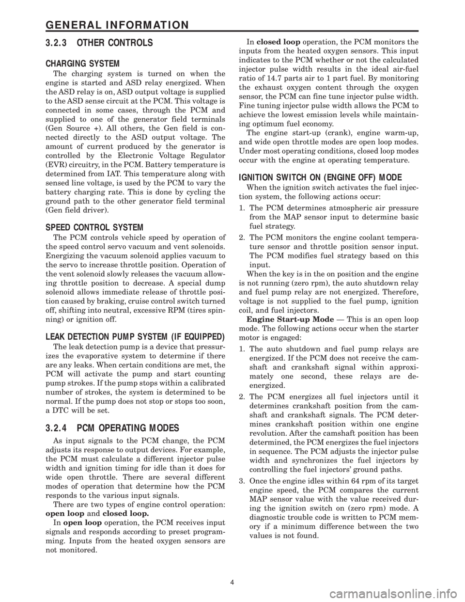
3.2.3 OTHER CONTROLS
CHARGING SYSTEM
The charging system is turned on when the
engine is started and ASD relay energized. When
the ASD relay is on, ASD output voltage is supplied
to the ASD sense circuit at the PCM. This voltage is
connected in some cases, through the PCM and
supplied to one of the generator field terminals
(Gen Source +). All others, the Gen field is con-
nected directly to the ASD output voltage. The
amount of current produced by the generator is
controlled by the Electronic Voltage Regulator
(EVR) circuitry, in the PCM. Battery temperature is
determined from IAT. This temperature along with
sensed line voltage, is used by the PCM to vary the
battery charging rate. This is done by cycling the
ground path to the other generator field terminal
(Gen field driver).
SPEED CONTROL SYSTEM
The PCM controls vehicle speed by operation of
the speed control servo vacuum and vent solenoids.
Energizing the vacuum solenoid applies vacuum to
the servo to increase throttle position. Operation of
the vent solenoid slowly releases the vacuum allow-
ing throttle position to decrease. A special dump
solenoid allows immediate release of throttle posi-
tion caused by braking, cruise control switch turned
off, shifting into neutral, excessive RPM (tires spin-
ning) or ignition off.
LEAK DETECTION PUMP SYSTEM (IF EQUIPPED)
The leak detection pump is a device that pressur-
izes the evaporative system to determine if there
are any leaks. When certain conditions are met, the
PCM will activate the pump and start counting
pump strokes. If the pump stops within a calibrated
number of strokes, the system is determined to be
normal. If the pump does not stop or stops too soon,
a DTC will be set.
3.2.4 PCM OPERATING MODES
As input signals to the PCM change, the PCM
adjusts its response to output devices. For example,
the PCM must calculate a different injector pulse
width and ignition timing for idle than it does for
wide open throttle. There are several different
modes of operation that determine how the PCM
responds to the various input signals.
There are two types of engine control operation:
open loopandclosed loop.
Inopen loopoperation, the PCM receives input
signals and responds according to preset program-
ming. Inputs from the heated oxygen sensors are
not monitored.Inclosed loopoperation, the PCM monitors the
inputs from the heated oxygen sensors. This input
indicates to the PCM whether or not the calculated
injector pulse width results in the ideal air-fuel
ratio of 14.7 parts air to 1 part fuel. By monitoring
the exhaust oxygen content through the oxygen
sensor, the PCM can fine tune injector pulse width.
Fine tuning injector pulse width allows the PCM to
achieve the lowest emission levels while maintain-
ing optimum fuel economy.
The engine start-up (crank), engine warm-up,
and wide open throttle modes are open loop modes.
Under most operating conditions, closed loop modes
occur with the engine at operating temperature.
IGNITION SWITCH ON (ENGINE OFF) MODE
When the ignition switch activates the fuel injec-
tion system, the following actions occur:
1. The PCM determines atmospheric air pressure
from the MAP sensor input to determine basic
fuel strategy.
2. The PCM monitors the engine coolant tempera-
ture sensor and throttle position sensor input.
The PCM modifies fuel strategy based on this
input.
When the key is in the on position and the engine
is not running (zero rpm), the auto shutdown relay
and fuel pump relay are not energized. Therefore,
voltage is not supplied to the fuel pump, ignition
coil, and fuel injectors.
Engine Start-up ModeÐ This is an open loop
mode. The following actions occur when the starter
motor is engaged:
1. The auto shutdown and fuel pump relays are
energized. If the PCM does not receive the cam-
shaft and crankshaft signal within approxi-
mately one second, these relays are de-
energized.
2. The PCM energizes all fuel injectors until it
determines crankshaft position from the cam-
shaft and crankshaft signals. The PCM deter-
mines crankshaft position within one engine
revolution. After the camshaft position has been
determined, the PCM energizes the fuel injectors
in sequence. The PCM adjusts the injector pulse
width and synchronizes the fuel injectors by
controlling the fuel injectors' ground paths.
3. Once the engine idles within 64 rpm of its target
engine speed, the PCM compares the current
MAP sensor value with the value received dur-
ing the ignition switch on (zero rpm) mode. A
diagnostic trouble code is written to PCM mem-
ory if a minimum difference between the two
values is not found.
4
GENERAL INFORMATION
Page 3799 of 4284
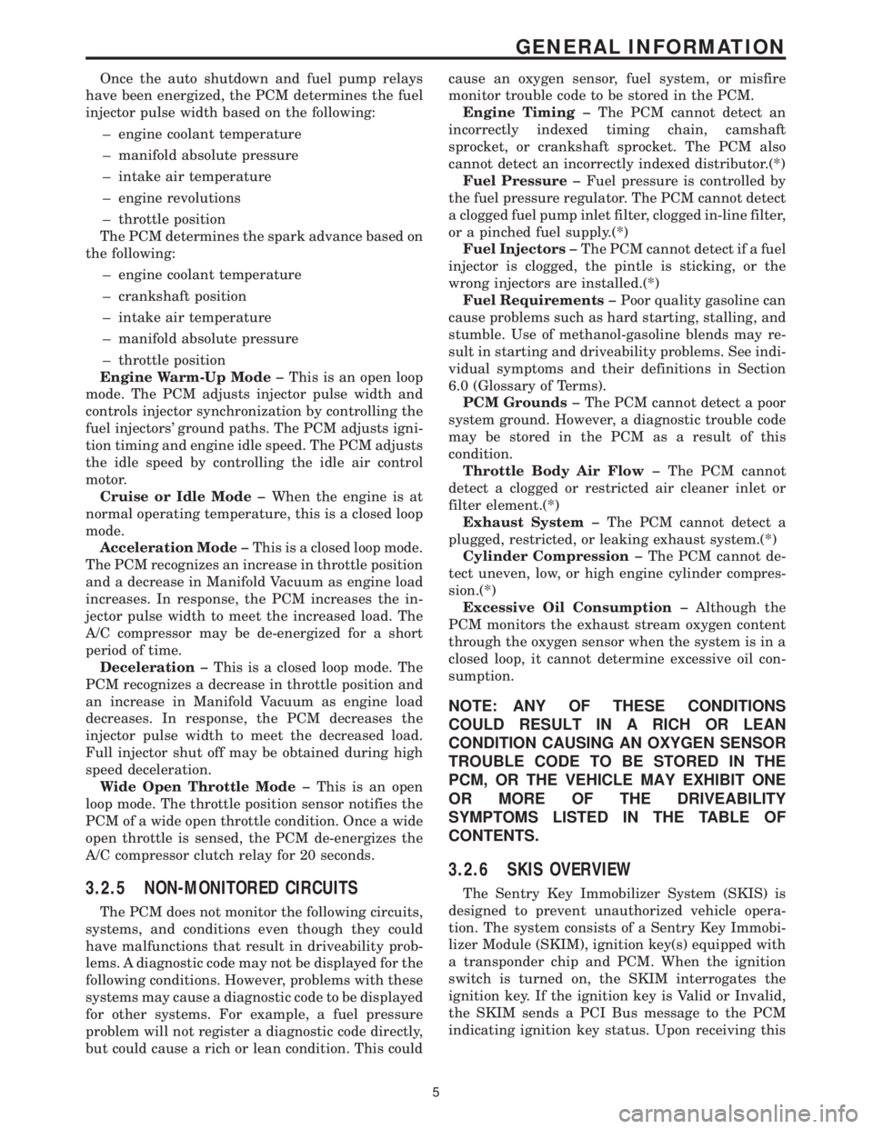
Once the auto shutdown and fuel pump relays
have been energized, the PCM determines the fuel
injector pulse width based on the following:
± engine coolant temperature
± manifold absolute pressure
± intake air temperature
± engine revolutions
± throttle position
The PCM determines the spark advance based on
the following:
± engine coolant temperature
± crankshaft position
± intake air temperature
± manifold absolute pressure
± throttle position
Engine Warm-Up Modeþ This is an open loop
mode. The PCM adjusts injector pulse width and
controls injector synchronization by controlling the
fuel injectors' ground paths. The PCM adjusts igni-
tion timing and engine idle speed. The PCM adjusts
the idle speed by controlling the idle air control
motor.
Cruise or Idle Modeþ When the engine is at
normal operating temperature, this is a closed loop
mode.
Acceleration Modeþ This is a closed loop mode.
The PCM recognizes an increase in throttle position
and a decrease in Manifold Vacuum as engine load
increases. In response, the PCM increases the in-
jector pulse width to meet the increased load. The
A/C compressor may be de-energized for a short
period of time.
Decelerationþ This is a closed loop mode. The
PCM recognizes a decrease in throttle position and
an increase in Manifold Vacuum as engine load
decreases. In response, the PCM decreases the
injector pulse width to meet the decreased load.
Full injector shut off may be obtained during high
speed deceleration.
Wide Open Throttle Modeþ This is an open
loop mode. The throttle position sensor notifies the
PCM of a wide open throttle condition. Once a wide
open throttle is sensed, the PCM de-energizes the
A/C compressor clutch relay for 20 seconds.
3.2.5 NON-MONITORED CIRCUITS
The PCM does not monitor the following circuits,
systems, and conditions even though they could
have malfunctions that result in driveability prob-
lems. A diagnostic code may not be displayed for the
following conditions. However, problems with these
systems may cause a diagnostic code to be displayed
for other systems. For example, a fuel pressure
problem will not register a diagnostic code directly,
but could cause a rich or lean condition. This couldcause an oxygen sensor, fuel system, or misfire
monitor trouble code to be stored in the PCM.
Engine Timingþ The PCM cannot detect an
incorrectly indexed timing chain, camshaft
sprocket, or crankshaft sprocket. The PCM also
cannot detect an incorrectly indexed distributor.(*)
Fuel Pressureþ Fuel pressure is controlled by
the fuel pressure regulator. The PCM cannot detect
a clogged fuel pump inlet filter, clogged in-line filter,
or a pinched fuel supply.(*)
Fuel Injectorsþ The PCM cannot detect if a fuel
injector is clogged, the pintle is sticking, or the
wrong injectors are installed.(*)
Fuel Requirementsþ Poor quality gasoline can
cause problems such as hard starting, stalling, and
stumble. Use of methanol-gasoline blends may re-
sult in starting and driveability problems. See indi-
vidual symptoms and their definitions in Section
6.0 (Glossary of Terms).
PCM Groundsþ The PCM cannot detect a poor
system ground. However, a diagnostic trouble code
may be stored in the PCM as a result of this
condition.
Throttle Body Air Flowþ The PCM cannot
detect a clogged or restricted air cleaner inlet or
filter element.(*)
Exhaust Systemþ The PCM cannot detect a
plugged, restricted, or leaking exhaust system.(*)
Cylinder Compressionþ The PCM cannot de-
tect uneven, low, or high engine cylinder compres-
sion.(*)
Excessive Oil Consumptionþ Although the
PCM monitors the exhaust stream oxygen content
through the oxygen sensor when the system is in a
closed loop, it cannot determine excessive oil con-
sumption.
NOTE: ANY OF THESE CONDITIONS
COULD RESULT IN A RICH OR LEAN
CONDITION CAUSING AN OXYGEN SENSOR
TROUBLE CODE TO BE STORED IN THE
PCM, OR THE VEHICLE MAY EXHIBIT ONE
OR MORE OF THE DRIVEABILITY
SYMPTOMS LISTED IN THE TABLE OF
CONTENTS.
3.2.6 SKIS OVERVIEW
The Sentry Key Immobilizer System (SKIS) is
designed to prevent unauthorized vehicle opera-
tion. The system consists of a Sentry Key Immobi-
lizer Module (SKIM), ignition key(s) equipped with
a transponder chip and PCM. When the ignition
switch is turned on, the SKIM interrogates the
ignition key. If the ignition key is Valid or Invalid,
the SKIM sends a PCI Bus message to the PCM
indicating ignition key status. Upon receiving this
5
GENERAL INFORMATION