2001 CHRYSLER VOYAGER key
[x] Cancel search: keyPage 3381 of 4284
BODY
TABLE OF CONTENTS
page page
BODY
DESCRIPTION............................1
WARNING...............................2
DIAGNOSIS AND TESTING..................2
WATER LEAKS..........................2
WIND NOISE...........................3
STANDARD PROCEDURE...................4
PLASTIC BODY PANEL REPAIR.............4
HEAT STAKING.........................8
SPECIFICATIONS.........................9
SPECIAL TOOLS........................151DOOR - FRONT.........................152
DOORS - SLIDING.......................162
DECKLID/HATCH/LIFTGATE/TAILGATE.......180
EXTERIOR.............................184
HOOD................................199
INSTRUMENT PANEL....................202
INTERIOR.............................208
PAINT................................220
SEATS................................222
STATIONARY GLASS.....................243
WEATHERSTRIP/SEALS..................248
BODY
DESCRIPTION - LOCK CYLINDERS
Ignition, door, deck lid, and rear hatch lock cylin-
ders are all codable to the key. Lock barrels, tum-
blers, and tumbler springs are available to allow the
technician to change replacement locks cylinders to
match the customer's original key set. See the appro-
priate section in this manual for lock cylinder
removal. See the Moparž catalogue for part numbers
and lock coding procedures.
DESCRIPTION - VEHICLE IDENTIFICATION
Throughout this group, references to the
DaimlerChrysler Corporation vehicle family identifi-
cation code are used when describing a procedure
that is unique to that vehicle. Refer to Introduction
Group of this manual for detailed information on
vehicle identification. If a procedure is common to all
vehicles covered in this manual, no reference will be
made to a vehicle family code.
DESCRIPTION - PUSH-IN FASTENERS
DaimlerChrysler Corporation uses many different
types of push-in fasteners to secure the interior and
exterior trim to the body. Most of these fasteners can
be reused to assemble the trim during various repair
procedures. At times, a push-in fastener cannot be
removed without damaging the fastener or the com-
ponent it is holding. If it is not possible to remove a
fastener without damaging a component or body, cut
or break the fastener and use a new one when
installing the component. Never pry or pound on a
plastic or pressed-board trim component. Using a
suitable fork-type prying device, pry the fastener
from the retaining hole behind the component beingremoved. When installing, verify fastener alignment
with the retaining hole by hand. Push directly on or
over the fastener until it seats. Apply a low-force pull
to the panel to verify that it is secure.
When it is necessary to remove components to ser-
vice another, it should not be necessary to apply
excessive force or bend a component to remove it.
Before damaging a trim component, verify hidden
fasteners or captured edges holding the component in
place.
DESCRIPTION
PAINT
The original equipment finish is a multi-step pro-
cess that involves cleaning, electrodeposition (e-coat),
base coat, and clear coat steps. Additionally, selected
areas of the vehicle may be coated with an anti-chip
finish.
On most vehicles a two-stage paint application
(base coat/clear coat) is used. Color that is applied to
primer is called base coat. The clear coat protects the
base coat from ultraviolet light and provides a dura-
ble high-gloss finish.
STATIONARY GLASS
Windshields are made of two pieces of glass with a
plastic inner layer. Windshields and selected station-
ary glass are structural members of the vehicle. The
windshield glass is bonded to the windshield frame
with urethane adhesive.
Windshields and other stationary glass protect the
occupants from the effects of the elements. Wind-
shields are also used to retain some airbags in posi-
tion during deployment. Urethane bonded glass is
difficult to salvage during removal. The urethane
bonding is difficult to cut or clean from any surface.
RSBODY23-1
Page 3389 of 4284
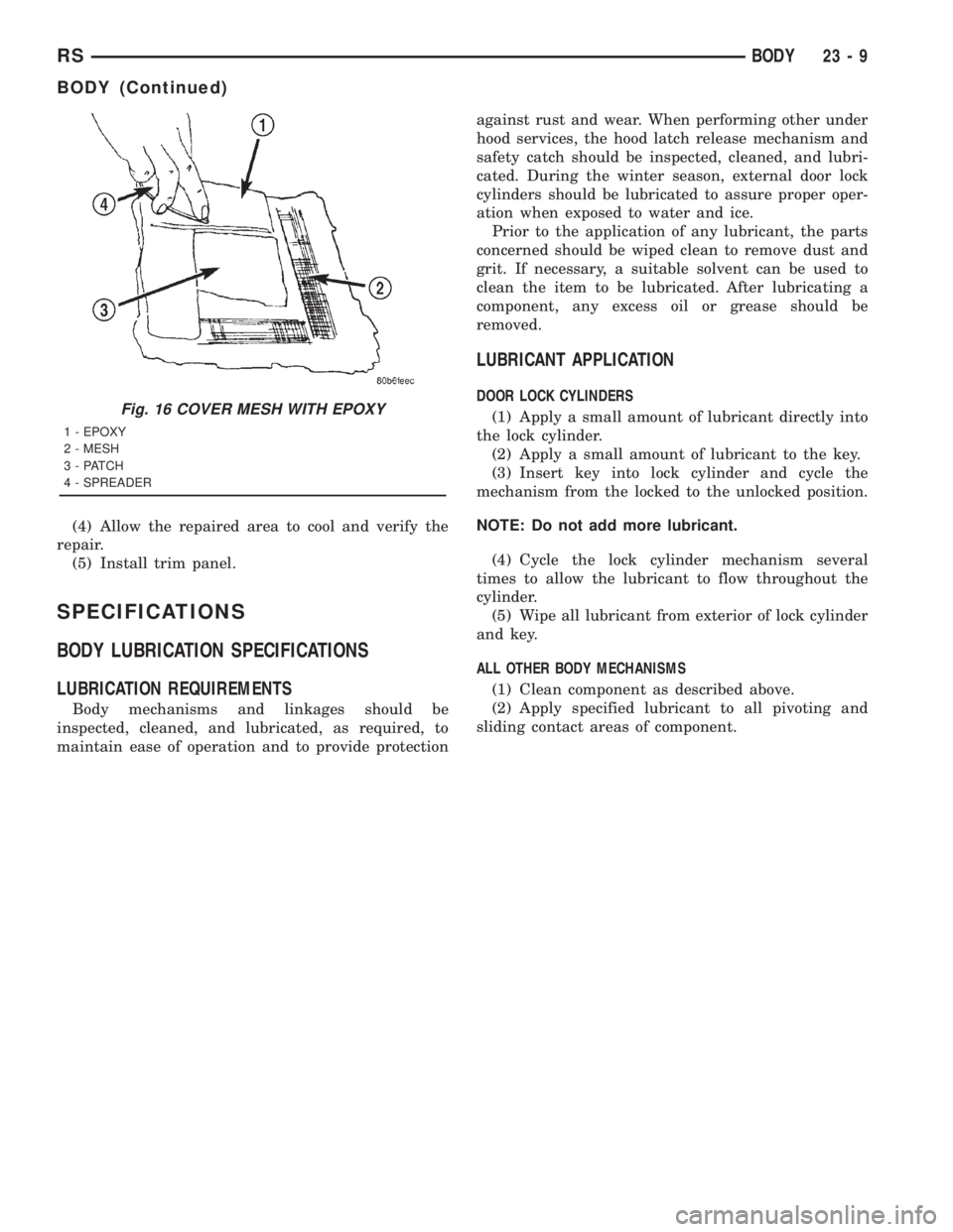
(4) Allow the repaired area to cool and verify the
repair.
(5) Install trim panel.
SPECIFICATIONS
BODY LUBRICATION SPECIFICATIONS
LUBRICATION REQUIREMENTS
Body mechanisms and linkages should be
inspected, cleaned, and lubricated, as required, to
maintain ease of operation and to provide protectionagainst rust and wear. When performing other under
hood services, the hood latch release mechanism and
safety catch should be inspected, cleaned, and lubri-
cated. During the winter season, external door lock
cylinders should be lubricated to assure proper oper-
ation when exposed to water and ice.
Prior to the application of any lubricant, the parts
concerned should be wiped clean to remove dust and
grit. If necessary, a suitable solvent can be used to
clean the item to be lubricated. After lubricating a
component, any excess oil or grease should be
removed.
LUBRICANT APPLICATION
DOOR LOCK CYLINDERS
(1) Apply a small amount of lubricant directly into
the lock cylinder.
(2) Apply a small amount of lubricant to the key.
(3) Insert key into lock cylinder and cycle the
mechanism from the locked to the unlocked position.
NOTE: Do not add more lubricant.
(4) Cycle the lock cylinder mechanism several
times to allow the lubricant to flow throughout the
cylinder.
(5) Wipe all lubricant from exterior of lock cylinder
and key.
ALL OTHER BODY MECHANISMS
(1) Clean component as described above.
(2) Apply specified lubricant to all pivoting and
sliding contact areas of component.Fig. 16 COVER MESH WITH EPOXY
1 - EPOXY
2 - MESH
3 - PATCH
4 - SPREADER
RSBODY23-9
BODY (Continued)
Page 3536 of 4284
INSTALLATION ± A-PILLAR, HEADER, OR
B-PILLAR
(1) Position closeout molding in window frame.
(2) Insert closeout molding into window frame
channel starting at the corners and working inward.
(3) Verify door glass operation.
HINGE
REMOVAL
(1) Release front door latch and open door.
(2) Support door on suitable lifting device.
(3) Remove bolts holding front door to door hinge.
(4) Remove bolts holding hinge to pillar.
(5) Remove door hinge from vehicle.
INSTALLATION
CAUTION: When installing a new hinge, make sure
that the head of each hinge pin is fully seated into
the door hinge. Also, remove the plastic shipping
clip and replace it with the correct metal retaining
clip once the hinge pin is seated.
(1) Paint hinge prior to installation, if necessary.
(2) Position door hinge on vehicle.
(3) Install bolts to hold hinge to pillar.
(4) Install bolts to hold front door to door hinge.
(5)
Align door to achieve equal spacing to surround-
ing body panels. Panels should be flush across all gaps.
(6) Verify door alignment and operation. Adjust as
necessary.
LATCH
REMOVAL
(1) Roll door glass up.
(2) Remove front door trim panel. (Refer to 23 -
BODY/DOOR - FRONT/TRIM PANEL - REMOVAL)
(3) Remove watershield as necessary to gain access
to the outside door handle.
(4) Through access hole at rear of inner door
panel, disconnect wire connector from power door
lock motor, if equipped.
(5) Disengage clips holding linkage to door latch.
(6) Remove linkages from door latch.
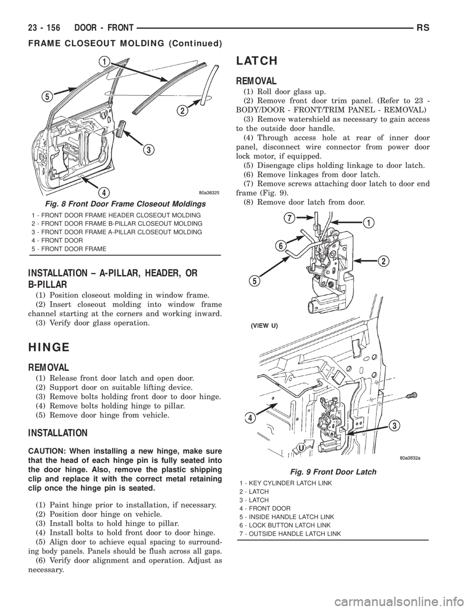
(7) Remove screws attaching door latch to door end
frame (Fig. 9).
(8) Remove door latch from door.
Fig. 8 Front Door Frame Closeout Moldings
1 - FRONT DOOR FRAME HEADER CLOSEOUT MOLDING
2 - FRONT DOOR FRAME B-PILLAR CLOSEOUT MOLDING
3 - FRONT DOOR FRAME A-PILLAR CLOSEOUT MOLDING
4 - FRONT DOOR
5 - FRONT DOOR FRAME
Fig. 9 Front Door Latch
1 - KEY CYLINDER LATCH LINK
2-LATCH
3-LATCH
4 - FRONT DOOR
5 - INSIDE HANDLE LATCH LINK
6 - LOCK BUTTON LATCH LINK
7 - OUTSIDE HANDLE LATCH LINK
23 - 156 DOOR - FRONTRS
FRAME CLOSEOUT MOLDING (Continued)
Page 3540 of 4284
WINDOW REGULATOR
REMOVAL
(1) Remove the watershield. (Refer to 23 - BODY/
DOOR - FRONT/WATERSHIELD - REMOVAL)
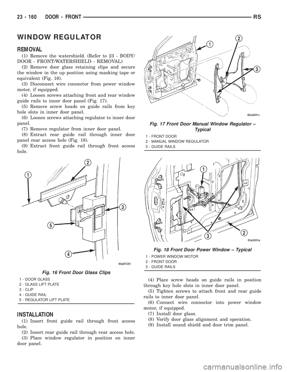
(2) Remove door glass retaining clips and secure
the window in the up position using masking tape or
equivalent (Fig. 16).
(3) Disconnect wire connector from power window
motor, if equipped.
(4) Loosen screws attaching front and rear window
guide rails to inner door panel (Fig. 17).
(5) Remove screw heads on guide rails from key
hole slots in inner door panel.
(6) Loosen screws attaching regulator to inner door
panel.
(7) Remove regulator from inner door panel.
(8) Extract rear guide rail through inner door
panel rear access hole (Fig. 18).
(9) Extract front guide rail through front access
hole.
INSTALLATION
(1) Insert front guide rail through front access
hole.
(2) Insert rear guide rail through rear access hole.
(3) Place window regulator in position on inner
door panel.(4) Place screw heads on guide rails in position
through key hole slots in inner door panel.
(5) Tighten screws to attach front and rear guide
rails to inner door panel.
(6) Connect wire connector into power window
motor, if equipped.
(7) Install door glass.
(8) Verify door glass alignment and operation.
(9) Install sound shield and door trim panel.
Fig. 16 Front Door Glass Clips
1 - DOOR GLASS
2 - GLASS LIFT PLATE
3 - CLIP
4 - GUIDE RAIL
5 - REGULATOR LIFT PLATE
Fig. 17 Front Door Manual Window Regulator ±
Typical
1 - FRONT DOOR
2 - MANUAL WINDOW REGULATOR
3 - GUIDE RAILS
Fig. 18 Front Door Power Window ± Typical
1 - POWER WINDOW MOTOR
2 - FRONT DOOR
3 - GUIDE RAILS
23 - 160 DOOR - FRONTRS
Page 3581 of 4284
(4) Align hood latch by placing latch over net
pierced tabs. If alignment is required, flatten or
grind tabs.
(5) Verify hood operation and alignment. Adjust as
necessary.
(6) Tighten attaching bolts to 13.5 N´m (10 ft. lbs.)
torque.
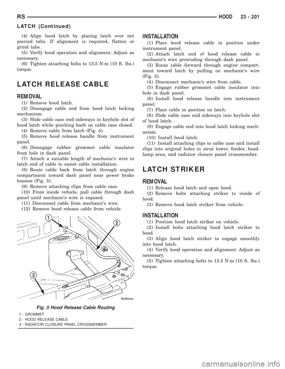
LATCH RELEASE CABLE
REMOVAL
(1) Remove hood latch.
(2) Disengage cable end from hood latch locking
mechanism.
(3) Slide cable case end sideways in keyhole slot of
hood latch while pinching barb on cable case closed.
(4) Remove cable from latch (Fig. 4).
(5) Remove hood release handle from instrument
panel.
(6) Disengage rubber grommet cable insulator
from hole in dash panel.
(7) Attach a suitable length of mechanic's wire to
latch end of cable to assist cable installation.
(8) Route cable back from latch through engine
compartment toward dash panel near power brake
booster (Fig. 5).
(9) Remove attaching clips from cable case.
(10) From inside vehicle, pull cable through dash
panel until mechanic's wire is exposed.
(11) Disconnect cable from mechanic's wire.
(12) Remove hood release cable from vehicle.
INSTALLATION
(1) Place hood release cable in position under
instrument panel.
(2) Attach latch end of hood release cable to
mechanic's wire protruding through dash panel.
(3) Route cable forward through engine compart-
ment toward latch by pulling on mechanic's wire
(Fig. 5).
(4) Disconnect mechanic's wire from cable.
(5) Engage rubber grommet cable insulator into
hole in dash panel.
(6) Install hood release handle into instrument
panel.
(7) Place cable in position on latch.
(8) Slide cable case end sideways into keyhole slot
of hood latch.
(9) Engage cable end into hood latch locking mech-
anism.
(10) Install hood latch.
(11) Install attaching clips to cable case and install
clips into original holes in strut tower, fender, head-
lamp area, and radiator closure panel crossmember.
LATCH STRIKER
REMOVAL
(1) Release hood latch and open hood.
(2) Remove bolts attaching striker to inside of
hood.
(3) Remove hood latch striker from vehicle.
INSTALLATION
(1) Position hood latch striker on vehicle.
(2) Install bolts attaching hood latch striker to
hood.
(3) Align hood latch striker to engage smoothly
into hood latch.
(4) Verify hood operation and alignment. Adjust as
necessary.
(5) Tighten attaching bolts to 13.5 N´m (10 ft. lbs.)
torque.
Fig. 5 Hood Release Cable Routing
1 - GROMMET
2 - HOOD RELEASE CABLE
3 - RADIATOR CLOSURE PANEL CROSSMEMBER
RSHOOD23 - 201
LATCH (Continued)
Page 3634 of 4284
cloudy days and at night it will probably be slightly
warmer. Infrared Three-Zone Temperature Control
provides side-to-side and front-to-rear variation in
comfort temperature settings. The Infrared Three-
Zone Automatic Temperature Control fan provides a
continuously variable air flow rate to meet occupant
comfort requirements.
FRONT CONTROL PANEL
²AUTO HI/LO± This system features two sets of
automatic control logic that allow either a rapid cool-
down rate or a somewhat slower cool-down rate with
less fan noise. HI-AUTO controls the system to reach
its assigned temperature quickly with a higher fan
speed. LO-AUTO controls the system to reach its
assigned temperature somewhat slower with less fan
noise. Both modes will automatically engage auto
recirculation.
²DE-FROST± The front de-frost function is
active when the rear window defogger function is
active or when the defog/defrost mode is selected.
²RECIRC± The RECIRC button will close the
air inlet door. If the system is in auto recirc (indica-
tor being displayed automatically), pressing the man-
ual recirc button will disable the auto recirc function
until one of the auto keys are pressed or the ignition
is cycled. If Auto HI/LO is pressed while manual
recirc is active, manual recirc will be deactivated.
²REAR WINDOW DEFOGGER± Pushing the
button sends a PCI bus message to the Intelligent
Power Module which controls the Rear Window
Defogger and side view mirror (if equipped) circuitry.
The defogger function will be active for 10 minutes
and can be turned off by a switch press. The defogger
will function while the control is in the OFF mode.
²FAN/MODE± The Fan and Mode knobs have
17 manual selectable positions. Manually changing
either of the rotary knobs for mode or fan speed set-
tings makes control of that function alone manual for
as long as the ignition is on. If only one is changed
manually, the other remains under automatic control.
Pressing the HI-AUTO/LO-AUTO rocker switch
restores full automatic control.
²REAR CONTROL± When the Rear System
control knob is moved to the OFF position, there will
be a delay of approximately 1 second before the sys-
tem actually turns off. This delay is to prevent an
undesired blower dropout if the knob is moved
through OFF to the other selections.
²BLOWER DELAY TIMER± The word DELAY
is displayed at start-up to signify that the system is
waiting so that cold air will not be blowing. This tells
the operator that it is unnecessary to turn the sys-
tem off, raise the temperature setting or turn the fan
speed setting down to prevent cold air from blowing.
A countdown in minutes and seconds until the engineis warm enough to begin delivering heat to the pas-
sengers alternates with the DELAY message at 25
second intervals. This countdown is based on actual
measurement of the rate of engine coolant tempera-
ture change. During the delay time, Defrost mode is
selected and the fan operates at a low speed to keep
the windshield fog free.
REAR CONTROL PANEL
Primary control of the rear compartment unit is in
the instrument panel center stack. The rear unit con-
trol knob there allows the driver to turn the rear
unit off, allow control by the intermediate seat occu-
pants by switching to the REAR position, or provide
fully automatic control based on the temperature set-
ting shown on the front control display.
²REAR CONTROL± Selecting automatic control
of the rear unit at the instrument panel, illuminates
a Locked Padlock in the rear control panel display.
Selecting REAR activates the rear control panel and
the Padlock then appears unlocked.
²FAN KNOB± The rear fan control has Off and
AUTO positions and a range of manual speed set-
tings that override the AUTO setting.
²MODE KNOB± The mode control allows inter-
mediate seat occupants to manually override the
automatic mode and select any balance of air flow
between overhead and floor outlets from full over-
head to full floor.
²SET TEMP± The rear set temp control will
operate identical to the front controls. If the front
control rear set temp button is pressed simulta-
neously with the rear control head, then the front
control head press events shall have priority, i.e. if
the front user presses Rear Set Temp down and the
rear user presses Set Temp up, then the rear set
temp will decrease.
DIAGNOSIS AND TESTING - A/C COOL DOWN
TEST
The heater-A/C control module can perform an A/C
cool down test, which is a test performed during the
manufacturing process to confirm that the air condi-
tioning system is performing satisfactorily. This test
can also provide a quick confirmation of air condi-
tioning system performance to the service technician.
If the test is completed satisfactorily, no further ser-
vice is required. If the test is failed, proceed to the
A/C Performance Test to confirm the a/c system is
operating properly, or use a DRBIIItscan tool to
diagnose the A/C system control and distribution sys-
tems. Refer to the appropriate diagnostic informa-
tion.
24 - 4 HEATING & AIR CONDITIONINGRS
HEATING & AIR CONDITIONING (Continued)
Page 3647 of 4284
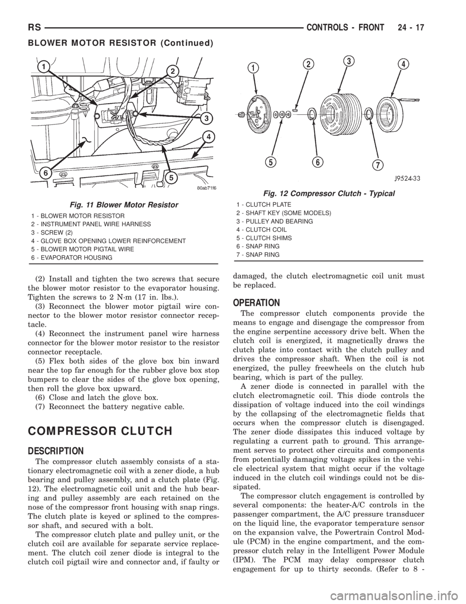
(2) Install and tighten the two screws that secure
the blower motor resistor to the evaporator housing.
Tighten the screws to 2 N´m (17 in. lbs.).
(3) Reconnect the blower motor pigtail wire con-
nector to the blower motor resistor connector recep-
tacle.
(4) Reconnect the instrument panel wire harness
connector for the blower motor resistor to the resistor
connector receptacle.
(5) Flex both sides of the glove box bin inward
near the top far enough for the rubber glove box stop
bumpers to clear the sides of the glove box opening,
then roll the glove box upward.
(6) Close and latch the glove box.
(7) Reconnect the battery negative cable.
COMPRESSOR CLUTCH
DESCRIPTION
The compressor clutch assembly consists of a sta-
tionary electromagnetic coil with a zener diode, a hub
bearing and pulley assembly, and a clutch plate (Fig.
12). The electromagnetic coil unit and the hub bear-
ing and pulley assembly are each retained on the
nose of the compressor front housing with snap rings.
The clutch plate is keyed or splined to the compres-
sor shaft, and secured with a bolt.
The compressor clutch plate and pulley unit, or the
clutch coil are available for separate service replace-
ment. The clutch coil zener diode is integral to the
clutch coil pigtail wire and connector and, if faulty ordamaged, the clutch electromagnetic coil unit must
be replaced.
OPERATION
The compressor clutch components provide the
means to engage and disengage the compressor from
the engine serpentine accessory drive belt. When the
clutch coil is energized, it magnetically draws the
clutch plate into contact with the clutch pulley and
drives the compressor shaft. When the coil is not
energized, the pulley freewheels on the clutch hub
bearing, which is part of the pulley.
A zener diode is connected in parallel with the
clutch electromagnetic coil. This diode controls the
dissipation of voltage induced into the coil windings
by the collapsing of the electromagnetic fields that
occurs when the compressor clutch is disengaged.
The zener diode dissipates this induced voltage by
regulating a current path to ground. This arrange-
ment serves to protect other circuits and components
from potentially damaging voltage spikes in the vehi-
cle electrical system that might occur if the voltage
induced in the clutch coil windings could not be dis-
sipated.
The compressor clutch engagement is controlled by
several components: the heater-A/C controls in the
passenger compartment, the A/C pressure transducer
on the liquid line, the evaporator temperature sensor
on the expansion valve, the Powertrain Control Mod-
ule (PCM) in the engine compartment, and the com-
pressor clutch relay in the Intelligent Power Module
(IPM). The PCM may delay compressor clutch
engagement for up to thirty seconds. (Refer to 8 -
Fig. 11 Blower Motor Resistor
1 - BLOWER MOTOR RESISTOR
2 - INSTRUMENT PANEL WIRE HARNESS
3 - SCREW (2)
4 - GLOVE BOX OPENING LOWER REINFORCEMENT
5 - BLOWER MOTOR PIGTAIL WIRE
6 - EVAPORATOR HOUSING
Fig. 12 Compressor Clutch - Typical
1 - CLUTCH PLATE
2 - SHAFT KEY (SOME MODELS)
3 - PULLEY AND BEARING
4 - CLUTCH COIL
5 - CLUTCH SHIMS
6 - SNAP RING
7 - SNAP RING
RSCONTROLS - FRONT24-17
BLOWER MOTOR RESISTOR (Continued)
Page 3748 of 4284
NOTE:Do not activate the Dosing Pump Prime more
than one time. This will put excess fuel in the DCHA
Heater Module an cause smoke to emit from the
DCHA exhaust pipe when heater activation occurs.
NOTE: A clicking noise heard coming from the Dos-
ing Pump indicates that the pump is operational.
(7)
With the DRBIIItin Cabin Heater, select Sys-
tem Tests and Dosing Pump Prime. Allow the Dosing
Pump to run for the full 45 second cycle time. When
the 45 second cycle is complete, press Page Back on
the DRBIIItkey pad to exit the Dosing Pump Prime.
The Dosing Pump priming procedure is now complete.
HEATER UNIT
REMOVAL
WARNING: ALLOW THE DCHA TO COOL BEFORE
PERFORMING A COMPONENT INSPECTION/REPAIR
OR REPLACEMENT. FAILURE TO FOLLOW THESE
INSTRUCTIONS MAY RESULT IN PERSONAL
INJURY.
WARNING: ALLOW THE EXHAUST SYSTEM TO
COOL BEFORE PERFORMING A COMPONENT
INSPECTION/REPAIR OR REPLACEMENT. FAILURE
TO FOLLOW THESE INSTRUCTION MAY RESULT IN
PERSONAL INJURY.
(1) Elevate the vehicle on a hoist/lift taking note of
heater exhaust tube flexible section.
(2) Drain cooling system(Refer to 7 - COOLING -
STANDARD PROCEDURE).
(3) Carefully open one hose to the underbody tube
assembly and drain the remaining coolant. A salvage
hose is a good idea to control the residual coolant, as
flow will occur from both the heater and the hose and
tube assemblies.
(4) Remove the second hose from the underbody
hose and tube assembly.
(5) Loosen the hose and tube assembly from the
toe-board cross member at two locations.
(6) Disconnect the electrical connector from the
body harness near the toe board cross member and
rail.
(7) Remove the wiring harness from the toe board
cross member(Refer to 24 - HEATING & AIR CON-
DITIONING/CABIN HEATER/HEATER UNIT -
REMOVAL).
(8) Open the fuel fill cap. Disconnect the rubber
fuel hose between the body tube assembly and the
fuel pump nipple at the body tube joint. A minimal
amount of fuel may flow from the open port.NOTE: Utilize an approved fuel storage container to
catch any residual fuel.
(9) Loosen the two M8 fasteners at the rail. Take
care to notice that the exhaust tube bracket tab is on
top of the heater bracket.
(10) Remove the heater exhaust tube flex section
from the exhaust tube by loosening the M6 bolt of
the clamp assembly. Remove the hose from the
exhaust tube. Removal of the rail tube assembly may
aid in this service operation.(Refer to 24 - HEATING
& AIR CONDITIONING/CABIN HEATER/EXHAUST
TUBE - REMOVAL).
(11) Remove seat hex nut at the heater mounting
flange to cross member.
(12) Loosen the remaining M6 and M8 fasteners
which mount the exhaust tube assembly to the vehi-
cle.
(a) Install a suitable cabin heater support device
under the cabin heater and secure the cabin heater
to the device.
(13) Loosen the remaining three M6 fasteners to
the cross members.
(14) Remove the loosened fasteners that support
the heater while supporting the weight of the heater.
(15) Swing the unit mounting bracket from
between the exhaust bracket and rail mounting loca-
tion. Drain any residual coolant from the heater unit.
(16) Lower the cabin heater and remove from the
supporting device and place on a suitable work area.
INSTALLATION
(1) Install the unit mounting bracket between the
exhaust bracket and the rail mounting location.
(2) Install the fasteners that support the heater
while supporting the weight of the heater.
(3) Install the three M6 fasteners to the cross
members. Tighten the M6 fasteners to 7 Nm (5 ft.
lbs.).
(4) Tighten the remaining M6 fasteners to 7 Nm (5
ft. lbs.) and the M8 fasteners to 23 Nm (17 ft. lbs.)
which mount the exhaust tube assembly to the vehi-
cle.
(5) Install the seat hex nut at the heater mounting
flange to the cross members. Tighten to 60 Nm (44 ft.
lbs.)
(6) Install the heater exhaust tube flex section to
the exhaust tube by tightening the M6 bolt of the
clamp assembly. Install the hose to the exhaust tube.
(7) Tighten the two M8 fasteners at the rail to 23
Nm (17 ft. lbs.). Taking care so that the exhaust tube
bracket tab is on the top of the heater bracket.
(8) Install the wiring harness(Refer to 24 - HEAT-
ING & AIR CONDITIONING/CABIN HEATER/
HEATER UNIT - INSTALLATION).
24a - 10 HEATING & AIR CONDITIONINGRG
FUEL LINE (Continued)