Page 2445 of 4284
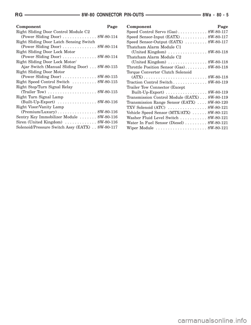
Component Page
Right Sliding Door Control Module C2
(Power Sliding Door).............. 8W-80-114
Right Sliding Door Latch Sensing Switch
(Power Sliding Door).............. 8W-80-114
Right Sliding Door Lock Motor
(Power Sliding Door).............. 8W-80-114
Right Sliding Door Lock Motor/
Ajar Switch (Manual Sliding Door) . . . 8W-80-115
Right Sliding Door Motor
(Power Sliding Door).............. 8W-80-115
Right Speed Control Switch.......... 8W-80-115
Right Stop/Turn Signal Relay
(Trailer Tow).................... 8W-80-115
Right Turn Signal Lamp
(Built-Up-Export)................ 8W-80-116
Right Visor/Vanity Lamp
(Premium/Luxury)................ 8W-80-116
Sentry Key Immobilizer Module....... 8W-80-116
Siren (United Kingdom)............. 8W-80-116
Solenoid/Pressure Switch Assy (EATX) . . 8W-80-117Component Page
Speed Control Servo (Gas)............ 8W-80-117
Speed Sensor-Input (EATX)........... 8W-80-117
Speed Sensor-Output (EATX)......... 8W-80-117
Thatcham Alarm Module C1
(United Kingdom)................ 8W-80-118
Thatcham Alarm Module C2
(United Kingdom)................ 8W-80-118
Throttle Position Sensor (Gas)......... 8W-80-118
Torque Converter Clutch Solenoid
(ATX).......................... 8W-80-118
Traction Control Switch.............. 8W-80-119
Trailer Tow Connector (Except
Built-Up-Export)................. 8W-80-119
Transmission Control Module (EATX) . . . 8W-80-119
Transmission Range Sensor (EATX).... 8W-80-120
TXV Solenoid (ATC)................ 8W-80-121
Vehicle Speed Sensor (MTX/ATX)...... 8W-80-121
Washer Fluid Level Switch........... 8W-80-121
Water In Fuel Sensor (Diesel)......... 8W-80-121
Wiper Module..................... 8W-80-121
RG8W-80 CONNECTOR PIN-OUTS8Wa-80-5
Page 2453 of 4284
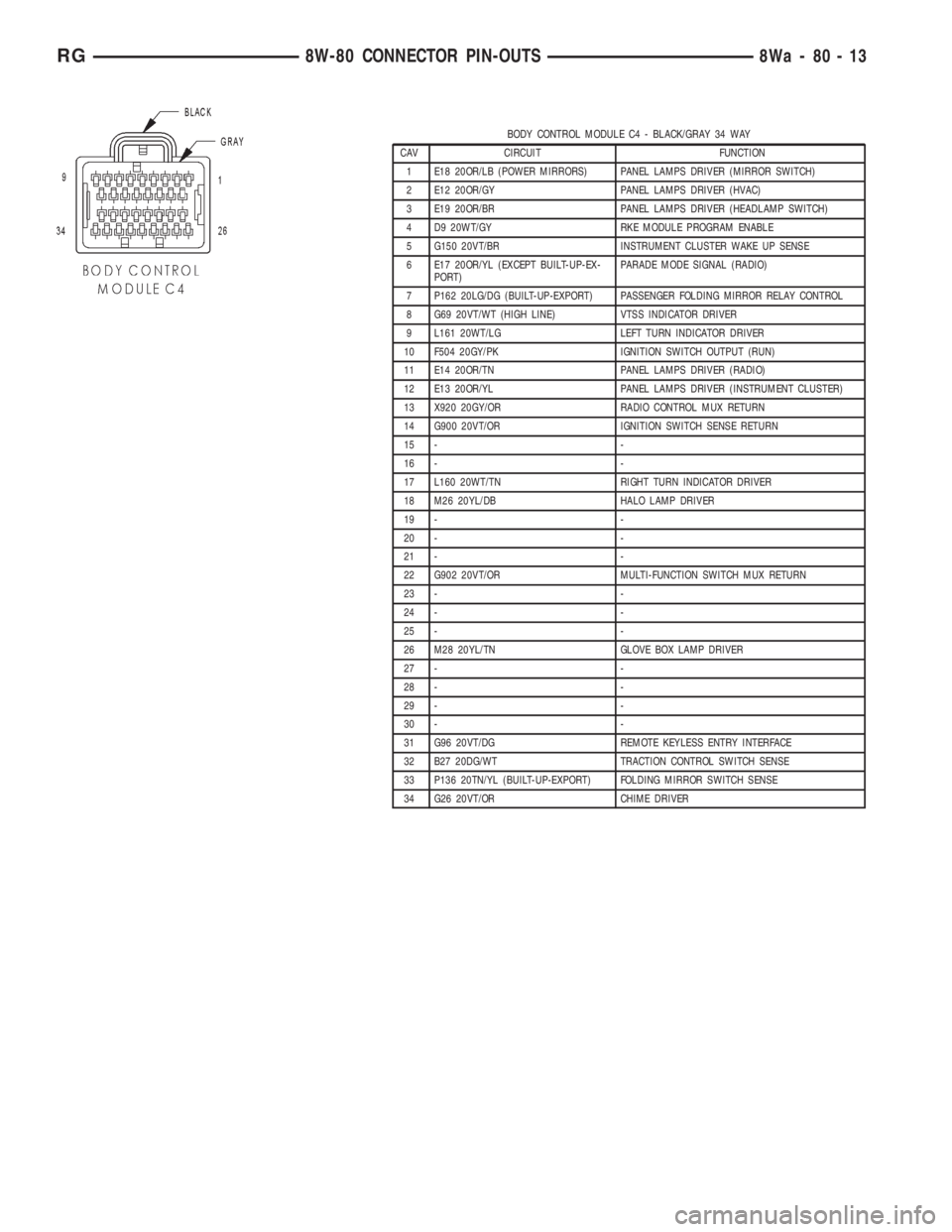
BODY CONTROL MODULE C4 - BLACK/GRAY 34 WAY
CAV CIRCUIT FUNCTION
1 E18 20OR/LB (POWER MIRRORS) PANEL LAMPS DRIVER (MIRROR SWITCH)
2 E12 20OR/GY PANEL LAMPS DRIVER (HVAC)
3 E19 20OR/BR PANEL LAMPS DRIVER (HEADLAMP SWITCH)
4 D9 20WT/GY RKE MODULE PROGRAM ENABLE
5 G150 20VT/BR INSTRUMENT CLUSTER WAKE UP SENSE
6 E17 20OR/YL (EXCEPT BUILT-UP-EX-
PORT)PARADE MODE SIGNAL (RADIO)
7 P162 20LG/DG (BUILT-UP-EXPORT) PASSENGER FOLDING MIRROR RELAY CONTROL
8 G69 20VT/WT (HIGH LINE) VTSS INDICATOR DRIVER
9 L161 20WT/LG LEFT TURN INDICATOR DRIVER
10 F504 20GY/PK IGNITION SWITCH OUTPUT (RUN)
11 E14 20OR/TN PANEL LAMPS DRIVER (RADIO)
12 E13 20OR/YL PANEL LAMPS DRIVER (INSTRUMENT CLUSTER)
13 X920 20GY/OR RADIO CONTROL MUX RETURN
14 G900 20VT/OR IGNITION SWITCH SENSE RETURN
15 - -
16 - -
17 L160 20WT/TN RIGHT TURN INDICATOR DRIVER
18 M26 20YL/DB HALO LAMP DRIVER
19 - -
20 - -
21 - -
22 G902 20VT/OR MULTI-FUNCTION SWITCH MUX RETURN
23 - -
24 - -
25 - -
26 M28 20YL/TN GLOVE BOX LAMP DRIVER
27 - -
28 - -
29 - -
30 - -
31 G96 20VT/DG REMOTE KEYLESS ENTRY INTERFACE
32 B27 20DG/WT TRACTION CONTROL SWITCH SENSE
33 P136 20TN/YL (BUILT-UP-EXPORT) FOLDING MIRROR SWITCH SENSE
34 G26 20VT/OR CHIME DRIVER
RG8W-80 CONNECTOR PIN-OUTS8Wa-80-13
Page 2547 of 4284
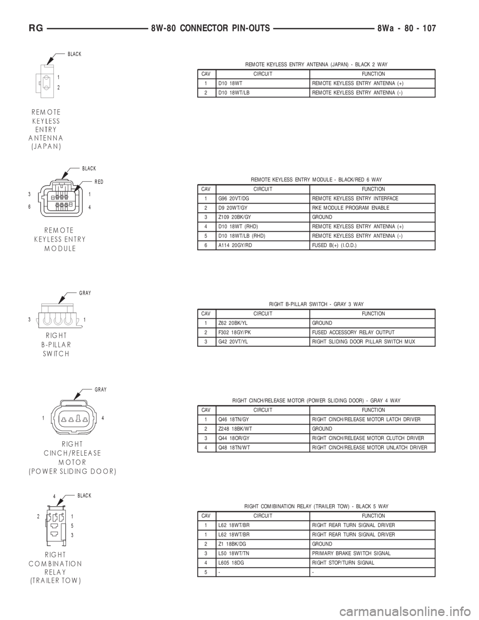
REMOTE KEYLESS ENTRY ANTENNA (JAPAN) - BLACK 2 WAY
CAV CIRCUIT FUNCTION
1 D10 18WT REMOTE KEYLESS ENTRY ANTENNA (+)
2 D10 18WT/LB REMOTE KEYLESS ENTRY ANTENNA (-)
REMOTE KEYLESS ENTRY MODULE - BLACK/RED 6 WAY
CAV CIRCUIT FUNCTION
1 G96 20VT/DG REMOTE KEYLESS ENTRY INTERFACE
2 D9 20WT/GY RKE MODULE PROGRAM ENABLE
3 Z109 20BK/GY GROUND
4 D10 18WT (RHD) REMOTE KEYLESS ENTRY ANTENNA (+)
5 D10 18WT/LB (RHD) REMOTE KEYLESS ENTRY ANTENNA (-)
6 A114 20GY/RD FUSED B(+) (I.O.D.)
RIGHT B-PILLAR SWITCH - GRAY 3 WAY
CAV CIRCUIT FUNCTION
1 Z62 20BK/YL GROUND
2 F302 18GY/PK FUSED ACCESSORY RELAY OUTPUT
3 G42 20VT/YL RIGHT SLIDING DOOR PILLAR SWITCH MUX
RIGHT CINCH/RELEASE MOTOR (POWER SLIDING DOOR) - GRAY 4 WAY
CAV CIRCUIT FUNCTION
1 Q46 18TN/GY RIGHT CINCH/RELEASE MOTOR LATCH DRIVER
2 Z248 18BK/WT GROUND
3 Q44 18OR/GY RIGHT CINCH/RELEASE MOTOR CLUTCH DRIVER
4 Q48 18TN/WT RIGHT CINCH/RELEASE MOTOR UNLATCH DRIVER
RIGHT COMIBINATION RELAY (TRAILER TOW) - BLACK 5 WAY
CAV CIRCUIT FUNCTION
1 L62 18WT/BR RIGHT REAR TURN SIGNAL DRIVER
1 L62 18WT/BR RIGHT REAR TURN SIGNAL DRIVER
2 Z1 18BK/DG GROUND
3 L50 18WT/TN PRIMARY BRAKE SWITCH SIGNAL
4 L605 18DG RIGHT STOP/TURN SIGNAL
5- -
RG8W-80 CONNECTOR PIN-OUTS8Wa - 80 - 107
Page 2556 of 4284
RIGHT TURN SIGNAL LAMP (BUILT-UP-EXPORT) - ORANGE 2 WAY
CAV CIRCUIT FUNCTION
1 Z344 16BR GROUND
2 L60 16YL RIGHT FRONT TURN SIGNAL DRIVER
RIGHT VISOR/VANITY LAMP (PREMIUM/LUXURY) - BLACK 2 WAY
CAV CIRCUIT FUNCTION
A Z327 20BK/OR GROUND
B M27 20YL/LB READING LAMPS DRIVER
SENTRY KEY IMMOBILIZER MODULE - BLACK 6 WAY
CAV CIRCUIT FUNCTION
1- -
2 D25 20WT/VT PCI BUS
3- -
4 F20 20PK/WT IGNITION SWITCH OUTPUT (RUN-START)
5 Z120 20BK/WT GROUND
6 A114 20GY/RD FUSED B(+) (I.O.D.)
SIREN (UNITED KINGDOM) - BLACK 4 WAY
CAV CIRCUIT FUNCTION
1 D97 18WT/OR SIREN SIGNAL OUTPUT
2 D96 18WT/LB SIREN SIGNAL CONTROL
3 A600 18RD/LB SIREN SUPPLY
4 G944 18LB/BR SIREN SIGNAL RETURN
8Wa - 80 - 116 8W-80 CONNECTOR PIN-OUTSRG
Page 2571 of 4284
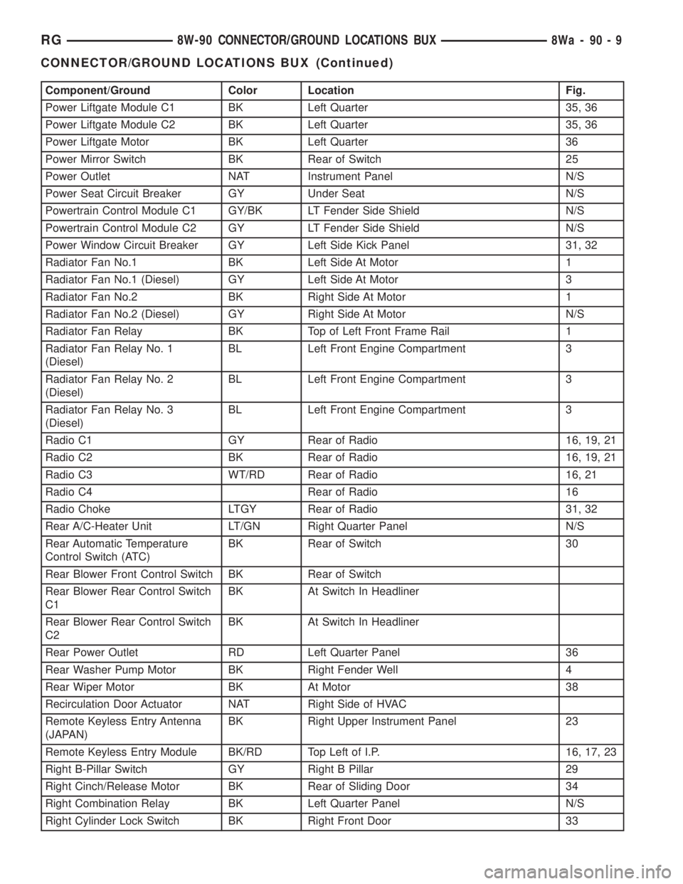
Component/Ground Color Location Fig.
Power Liftgate Module C1 BK Left Quarter 35, 36
Power Liftgate Module C2 BK Left Quarter 35, 36
Power Liftgate Motor BK Left Quarter 36
Power Mirror Switch BK Rear of Switch 25
Power Outlet NAT Instrument Panel N/S
Power Seat Circuit Breaker GY Under Seat N/S
Powertrain Control Module C1 GY/BK LT Fender Side Shield N/S
Powertrain Control Module C2 GY LT Fender Side Shield N/S
Power Window Circuit Breaker GY Left Side Kick Panel 31, 32
Radiator Fan No.1 BK Left Side At Motor 1
Radiator Fan No.1 (Diesel) GY Left Side At Motor 3
Radiator Fan No.2 BK Right Side At Motor 1
Radiator Fan No.2 (Diesel) GY Right Side At Motor N/S
Radiator Fan Relay BK Top of Left Front Frame Rail 1
Radiator Fan Relay No. 1
(Diesel)BL Left Front Engine Compartment 3
Radiator Fan Relay No. 2
(Diesel)BL Left Front Engine Compartment 3
Radiator Fan Relay No. 3
(Diesel)BL Left Front Engine Compartment 3
Radio C1 GY Rear of Radio 16, 19, 21
Radio C2 BK Rear of Radio 16, 19, 21
Radio C3 WT/RD Rear of Radio 16, 21
Radio C4 Rear of Radio 16
Radio Choke LTGY Rear of Radio 31, 32
Rear A/C-Heater Unit LT/GN Right Quarter Panel N/S
Rear Automatic Temperature
Control Switch (ATC)BK Rear of Switch 30
Rear Blower Front Control Switch BK Rear of Switch
Rear Blower Rear Control Switch
C1BK At Switch In Headliner
Rear Blower Rear Control Switch
C2BK At Switch In Headliner
Rear Power Outlet RD Left Quarter Panel 36
Rear Washer Pump Motor BK Right Fender Well 4
Rear Wiper Motor BK At Motor 38
Recirculation Door Actuator NAT Right Side of HVAC
Remote Keyless Entry Antenna
(JAPAN)BK Right Upper Instrument Panel 23
Remote Keyless Entry Module BK/RD Top Left of I.P. 16, 17, 23
Right B-Pillar Switch GY Right B Pillar 29
Right Cinch/Release Motor BK Rear of Sliding Door 34
Right Combination Relay BK Left Quarter Panel N/S
Right Cylinder Lock Switch BK Right Front Door 33
RG8W-90 CONNECTOR/GROUND LOCATIONS BUX8Wa-90-9
CONNECTOR/GROUND LOCATIONS BUX (Continued)
Page 2573 of 4284
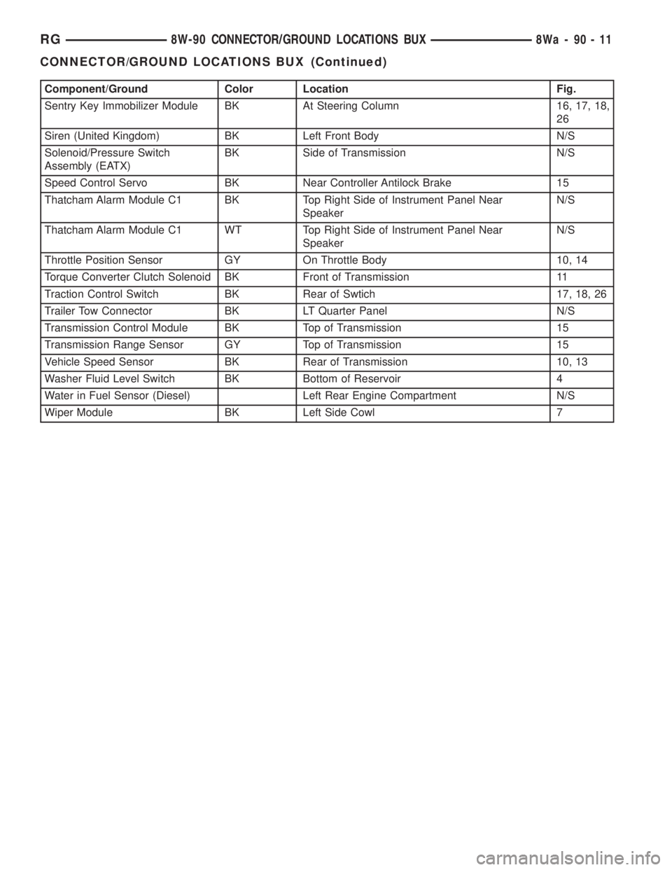
Component/Ground Color Location Fig.
Sentry Key Immobilizer Module BK At Steering Column 16, 17, 18,
26
Siren (United Kingdom) BK Left Front Body N/S
Solenoid/Pressure Switch
Assembly (EATX)BK Side of Transmission N/S
Speed Control Servo BK Near Controller Antilock Brake 15
Thatcham Alarm Module C1 BK Top Right Side of Instrument Panel Near
SpeakerN/S
Thatcham Alarm Module C1 WT Top Right Side of Instrument Panel Near
SpeakerN/S
Throttle Position Sensor GY On Throttle Body 10, 14
Torque Converter Clutch Solenoid BK Front of Transmission 11
Traction Control Switch BK Rear of Swtich 17, 18, 26
Trailer Tow Connector BK LT Quarter Panel N/S
Transmission Control Module BK Top of Transmission 15
Transmission Range Sensor GY Top of Transmission 15
Vehicle Speed Sensor BK Rear of Transmission 10, 13
Washer Fluid Level Switch BK Bottom of Reservoir 4
Water in Fuel Sensor (Diesel) Left Rear Engine Compartment N/S
Wiper Module BK Left Side Cowl 7
RG8W-90 CONNECTOR/GROUND LOCATIONS BUX8Wa-90-11
CONNECTOR/GROUND LOCATIONS BUX (Continued)
Page 2676 of 4284
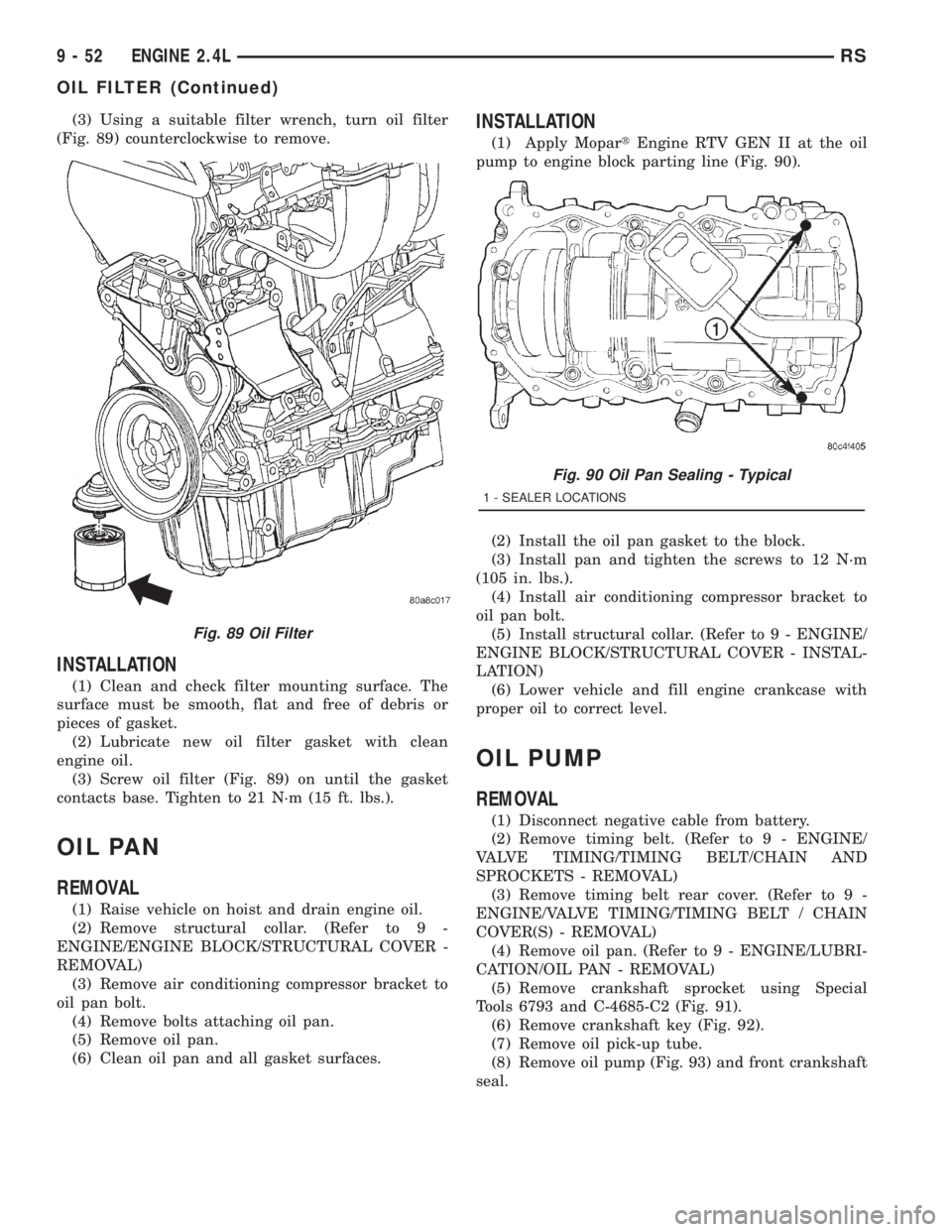
(3) Using a suitable filter wrench, turn oil filter
(Fig. 89) counterclockwise to remove.
INSTALLATION
(1) Clean and check filter mounting surface. The
surface must be smooth, flat and free of debris or
pieces of gasket.
(2) Lubricate new oil filter gasket with clean
engine oil.
(3) Screw oil filter (Fig. 89) on until the gasket
contacts base. Tighten to 21 N´m (15 ft. lbs.).
OIL PAN
REMOVAL
(1) Raise vehicle on hoist and drain engine oil.
(2) Remove structural collar. (Refer to 9 -
ENGINE/ENGINE BLOCK/STRUCTURAL COVER -
REMOVAL)
(3) Remove air conditioning compressor bracket to
oil pan bolt.
(4) Remove bolts attaching oil pan.
(5) Remove oil pan.
(6) Clean oil pan and all gasket surfaces.
INSTALLATION
(1) Apply MopartEngine RTV GEN II at the oil
pump to engine block parting line (Fig. 90).
(2) Install the oil pan gasket to the block.
(3) Install pan and tighten the screws to 12 N´m
(105 in. lbs.).
(4) Install air conditioning compressor bracket to
oil pan bolt.
(5) Install structural collar. (Refer to 9 - ENGINE/
ENGINE BLOCK/STRUCTURAL COVER - INSTAL-
LATION)
(6) Lower vehicle and fill engine crankcase with
proper oil to correct level.
OIL PUMP
REMOVAL
(1) Disconnect negative cable from battery.
(2) Remove timing belt. (Refer to 9 - ENGINE/
VALVE TIMING/TIMING BELT/CHAIN AND
SPROCKETS - REMOVAL)
(3) Remove timing belt rear cover. (Refer to 9 -
ENGINE/VALVE TIMING/TIMING BELT / CHAIN
COVER(S) - REMOVAL)
(4) Remove oil pan. (Refer to 9 - ENGINE/LUBRI-
CATION/OIL PAN - REMOVAL)
(5) Remove crankshaft sprocket using Special
Tools 6793 and C-4685-C2 (Fig. 91).
(6) Remove crankshaft key (Fig. 92).
(7) Remove oil pick-up tube.
(8) Remove oil pump (Fig. 93) and front crankshaft
seal.
Fig. 89 Oil Filter
Fig. 90 Oil Pan Sealing - Typical
1 - SEALER LOCATIONS
9 - 52 ENGINE 2.4LRS
OIL FILTER (Continued)
Page 2677 of 4284
DISASSEMBLY
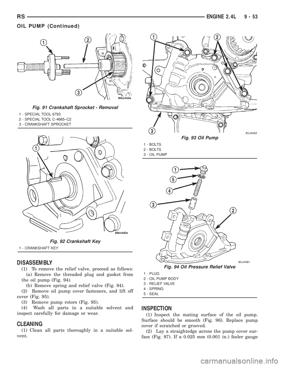
(1) To remove the relief valve, proceed as follows:
(a) Remove the threaded plug and gasket from
the oil pump (Fig. 94).
(b) Remove spring and relief valve (Fig. 94).
(2) Remove oil pump cover fasteners, and lift off
cover (Fig. 95).
(3) Remove pump rotors (Fig. 95).
(4) Wash all parts in a suitable solvent and
inspect carefully for damage or wear.
CLEANING
(1) Clean all parts thoroughly in a suitable sol-
vent.
INSPECTION
(1) Inspect the mating surface of the oil pump.
Surface should be smooth (Fig. 96). Replace pump
cover if scratched or grooved.
(2) Lay a straightedge across the pump cover sur-
face (Fig. 97). If a 0.025 mm (0.001 in.) feeler gauge
Fig. 91 Crankshaft Sprocket - Removal
1 - SPECIAL TOOL 6793
2 - SPECIAL TOOL C-4685±C2
3 - CRANKSHAFT SPROCKET
Fig. 92 Crankshaft Key
1 - CRANKSHAFT KEY
Fig. 93 Oil Pump
1 - BOLTS
2 - BOLTS
3 - OIL PUMP
Fig. 94 Oil Pressure Relief Valve
1 - PLUG
2 - OIL PUMP BODY
3 - RELIEF VALVE
4 - SPRING
5 - SEAL
RSENGINE 2.4L9-53
OIL PUMP (Continued)