2001 CHRYSLER VOYAGER airbag off
[x] Cancel search: airbag offPage 3639 of 4284
(3) The calibration procedure should take less than
three minutes to complete for the manual heater-A/C
control, and less than twenty seconds for the ATC
heater-A/C control. When the LEDs or graphics stop
flashing, the calibration procedure is complete.
(4) If the LEDs or graphics continue to flash
beyond the normal three minute (manual) or twenty
second (ATC) calibration time, it indicates that the
heater-A/C control has detected a failure and a Diag-
nostic Trouble Code (DTC) has been set. Use a
DRBIIItscan tool to perform further diagnosis. Refer
to the appropriate diagnostic information. The LEDs
or graphics will continue to flash even after the igni-
tion switch is cycled Off and On, until a successful
calibration is completed or until the vehicle has been
driven about 5 kilometers (3 miles).
REMOVAL
WARNING: ON VEHICLES EQUIPPED WITH AIR-
BAGS, DISABLE THE AIRBAG SYSTEM BEFORE
ATTEMPTING ANY STEERING WHEEL, STEERING
COLUMN, OR INSTRUMENT PANEL COMPONENT
DIAGNOSIS OR SERVICE. DISCONNECT AND ISO-
LATE THE BATTERY NEGATIVE (GROUND) CABLE,
THEN WAIT TWO MINUTES FOR THE AIRBAG SYS-
TEM CAPACITOR TO DISCHARGE BEFORE PER-
FORMING FURTHER DIAGNOSIS OR SERVICE. THIS
IS THE ONLY SURE WAY TO DISABLE THE AIRBAG
SYSTEM. FAILURE TO TAKE THE PROPER PRE-
CAUTIONS COULD RESULT IN ACCIDENTAL AIR-
BAG DEPLOYMENT AND POSSIBLE PERSONAL
INJURY.
(1) Disconnect and isolate the battery negative
cable.
(2) Remove the center bezel from the instrument
panel. (Refer to 23 - BODY/INSTRUMENT PANEL/
INSTRUMENT PANEL CENTER BEZEL - REMOV-
AL).
(3) Place the instrument panel center bezel unit
face down on a suitable work surface. Take the
proper precautions to protect the center bezel from
cosmetic damage.
(4) If the vehicle is equipped with the optional
Automatic Temperature Control (ATC) system, dis-
connect the infrared sensor jumper harness connector
from the receptacle on the back of the heater-A/C
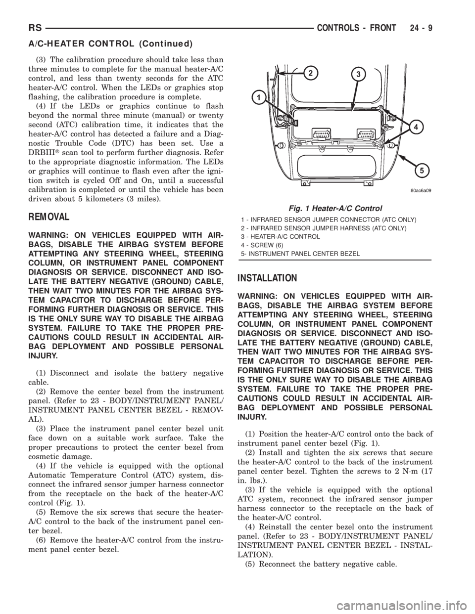
control (Fig. 1).
(5) Remove the six screws that secure the heater-
A/C control to the back of the instrument panel cen-
ter bezel.
(6) Remove the heater-A/C control from the instru-
ment panel center bezel.
INSTALLATION
WARNING: ON VEHICLES EQUIPPED WITH AIR-
BAGS, DISABLE THE AIRBAG SYSTEM BEFORE
ATTEMPTING ANY STEERING WHEEL, STEERING
COLUMN, OR INSTRUMENT PANEL COMPONENT
DIAGNOSIS OR SERVICE. DISCONNECT AND ISO-
LATE THE BATTERY NEGATIVE (GROUND) CABLE,
THEN WAIT TWO MINUTES FOR THE AIRBAG SYS-
TEM CAPACITOR TO DISCHARGE BEFORE PER-
FORMING FURTHER DIAGNOSIS OR SERVICE. THIS
IS THE ONLY SURE WAY TO DISABLE THE AIRBAG
SYSTEM. FAILURE TO TAKE THE PROPER PRE-
CAUTIONS COULD RESULT IN ACCIDENTAL AIR-
BAG DEPLOYMENT AND POSSIBLE PERSONAL
INJURY.
(1) Position the heater-A/C control onto the back of
instrument panel center bezel (Fig. 1).
(2) Install and tighten the six screws that secure
the heater-A/C control to the back of the instrument
panel center bezel. Tighten the screws to 2 N´m (17
in. lbs.).
(3) If the vehicle is equipped with the optional
ATC system, reconnect the infrared sensor jumper
harness connector to the receptacle on the back of
the heater-A/C control.
(4) Reinstall the center bezel onto the instrument
panel. (Refer to 23 - BODY/INSTRUMENT PANEL/
INSTRUMENT PANEL CENTER BEZEL - INSTAL-
LATION).
(5) Reconnect the battery negative cable.
Fig. 1 Heater-A/C Control
1 - INFRARED SENSOR JUMPER CONNECTOR (ATC ONLY)
2 - INFRARED SENSOR JUMPER HARNESS (ATC ONLY)
3 - HEATER-A/C CONTROL
4 - SCREW (6)
5- INSTRUMENT PANEL CENTER BEZEL
RSCONTROLS - FRONT24-9
A/C-HEATER CONTROL (Continued)
Page 3675 of 4284
BLOWER MOTOR
DESCRIPTION
The blower motor is a 12-volt, Direct Current (DC)
motor with a squirrel cage-type blower wheel that is
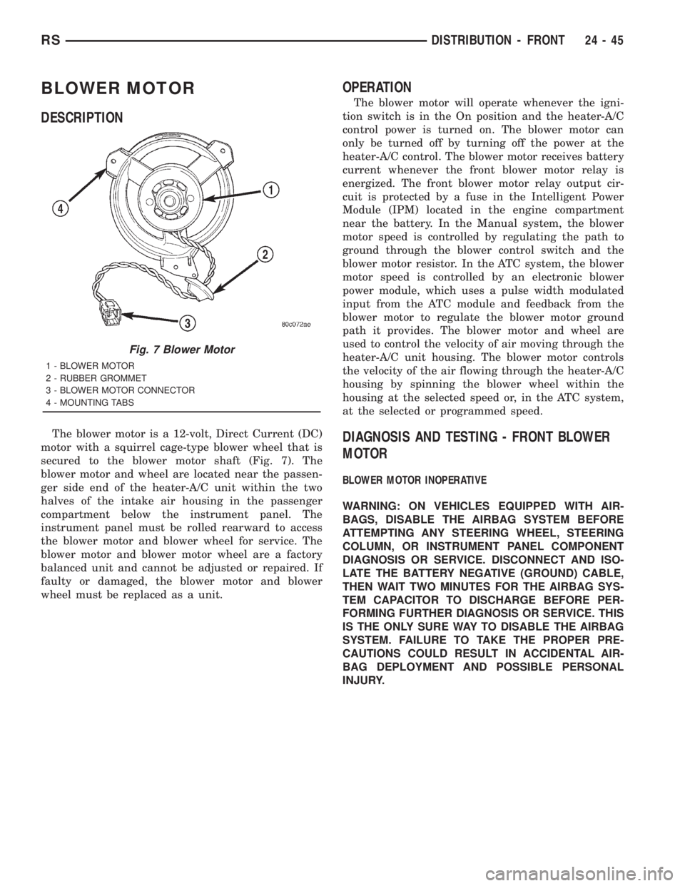
secured to the blower motor shaft (Fig. 7). The
blower motor and wheel are located near the passen-
ger side end of the heater-A/C unit within the two
halves of the intake air housing in the passenger
compartment below the instrument panel. The
instrument panel must be rolled rearward to access
the blower motor and blower wheel for service. The
blower motor and blower motor wheel are a factory
balanced unit and cannot be adjusted or repaired. If
faulty or damaged, the blower motor and blower
wheel must be replaced as a unit.
OPERATION
The blower motor will operate whenever the igni-
tion switch is in the On position and the heater-A/C
control power is turned on. The blower motor can
only be turned off by turning off the power at the
heater-A/C control. The blower motor receives battery
current whenever the front blower motor relay is
energized. The front blower motor relay output cir-
cuit is protected by a fuse in the Intelligent Power
Module (IPM) located in the engine compartment
near the battery. In the Manual system, the blower
motor speed is controlled by regulating the path to
ground through the blower control switch and the
blower motor resistor. In the ATC system, the blower
motor speed is controlled by an electronic blower
power module, which uses a pulse width modulated
input from the ATC module and feedback from the
blower motor to regulate the blower motor ground
path it provides. The blower motor and wheel are
used to control the velocity of air moving through the
heater-A/C unit housing. The blower motor controls
the velocity of the air flowing through the heater-A/C
housing by spinning the blower wheel within the
housing at the selected speed or, in the ATC system,
at the selected or programmed speed.
DIAGNOSIS AND TESTING - FRONT BLOWER
MOTOR
BLOWER MOTOR INOPERATIVE
WARNING: ON VEHICLES EQUIPPED WITH AIR-
BAGS, DISABLE THE AIRBAG SYSTEM BEFORE
ATTEMPTING ANY STEERING WHEEL, STEERING
COLUMN, OR INSTRUMENT PANEL COMPONENT
DIAGNOSIS OR SERVICE. DISCONNECT AND ISO-
LATE THE BATTERY NEGATIVE (GROUND) CABLE,
THEN WAIT TWO MINUTES FOR THE AIRBAG SYS-
TEM CAPACITOR TO DISCHARGE BEFORE PER-
FORMING FURTHER DIAGNOSIS OR SERVICE. THIS
IS THE ONLY SURE WAY TO DISABLE THE AIRBAG
SYSTEM. FAILURE TO TAKE THE PROPER PRE-
CAUTIONS COULD RESULT IN ACCIDENTAL AIR-
BAG DEPLOYMENT AND POSSIBLE PERSONAL
INJURY.
Fig. 7 Blower Motor
1 - BLOWER MOTOR
2 - RUBBER GROMMET
3 - BLOWER MOTOR CONNECTOR
4 - MOUNTING TABS
RSDISTRIBUTION - FRONT24-45
Page 3710 of 4284
INSTALLATION - HEATER CORE
WARNING: REFER TO THE APPLICABLE WARN-
INGS AND CAUTIONS FOR THIS SYSTEM BEFORE
PERFORMING THE FOLLOWING OPERATION.
(Refer to 24 - HEATING & AIR CONDITIONING/
PLUMBING FRONT - WARNING - HEATER PLUMB-
ING).
WARNING: ON VEHICLES EQUIPPED WITH AIR-
BAGS, DISABLE THE AIRBAG SYSTEM BEFORE
ATTEMPTING ANY STEERING WHEEL, STEERING
COLUMN, OR INSTRUMENT PANEL COMPONENT
DIAGNOSIS OR SERVICE. DISCONNECT AND ISO-
LATE THE BATTERY NEGATIVE (GROUND) CABLE,
THEN WAIT TWO MINUTES FOR THE AIRBAG SYS-
TEM CAPACITOR TO DISCHARGE BEFORE PER-
FORMING FURTHER DIAGNOSIS OR SERVICE. THIS
IS THE ONLY SURE WAY TO DISABLE THE AIRBAG
SYSTEM. FAILURE TO TAKE THE PROPER PRE-
CAUTIONS COULD RESULT IN ACCIDENTAL AIR-
BAG DEPLOYMENT AND POSSIBLE PERSONAL
INJURY.
(1) While pushing the brake pedal downward (Fig.
20) and pulling the accelerator pedal upward (Fig.
19) far enough for clearance, slide the heater core
into the distribution housing.
(2) Install and tighten the two screws that secure
the heater core mounting plate to the distribution
housing (Fig. 18). Tighten the screws to 2 N´m (17 in.
lbs.).
(3) Remove the plugs or tape from the heater core
tube fittings and both heater core ports.
(4) Position both heater core tubes and the sealing
plate simultaneously to the heater core supply and
return ports.
(5) The heater core tubes each have a slot that
must be indexed to a location tab within each of the
heater core ports. Adjust the position of the tubes as
required so that the sealing plate fits flush against
the heater core supply and return ports, which indi-
cates that the tubes are properly indexed.
(6) Install and tighten the screw that secures the
heater core tube sealing plate to the heater core sup-
ply and return ports. Tighten the screw to 3 N´m (27
in. lbs.).
(7) Position the heater core shield onto the distri-
bution housing. Be certain that the two location tabs
on the front of the shield are engaged in the recepta-
cles in the two lower finger formations of the evapo-
rator housing near the dash panel (Fig. 17).
(8) Install and tighten the three screws that secure
the heater core shield to the left end of the HVAC
distribution housing. Tighten the screws to 2 N´m (17
in. lbs.).(9) Reconnect the power brake booster input rod
(push rod) to the pin on the brake pedal arm. (Refer
to 5 - BRAKES - ABS/HYDRAULIC/MECHANICAL/
POWER BRAKE BOOSTER - INSTALLATION).
(10) Reinstall the brake lamp switch into its
mounting bracket. (Refer to 8 - ELECTRICAL/
LAMPS/LIGHTING - EXTERIOR/BRAKE LAMP
SWITCH - INSTALLATION).
(11) Reinstall the silencer boot around the base of
the lower steering shaft on the dash panel.
(12) Reconnect the battery negative cable.
(13) Refill the engine cooling system. (Refer to 7 -
COOLING - STANDARD PROCEDURE - COOLING
SYSTEM REFILL).
(14) Operate sustem for two thermostat cycles to
assure elimination of air in the system.
HEATER HOSE
REMOVAL
There are several heater core plumbing configura-
tions used on this model, depending upon the engine
size and other optional equipment. One plumbing
configuration is used for all 2.4L engines (Fig. 21),
while the 3.3L and 3.8L engines have unique heater
return plumbing on the engine for models with or
without an optional engine oil cooler (Fig. 24) or (Fig.
25). There are also unique plumbing configurations
at the heater core for models with or without the
optional rear heater and air conditioner (Fig. 22) or
(Fig. 23). All models use a combination of formed
steel tubing and rubber hoses. In most cases, the
rubber hose is secured to the steel tubing with a
spring tension clamp.
WARNING: REFER TO THE APPLICABLE WARN-
INGS AND CAUTIONS FOR THIS SYSTEM BEFORE
PERFORMING THE FOLLOWING OPERATION.
(Refer to 24 - HEATING & AIR CONDITIONING/
PLUMBING FRONT - WARNING - HEATER PLUMB-
ING).
(1) Drain the engine cooling system. (Refer to 7 -
COOLING - STANDARD PROCEDURE - COOLING
SYSTEM DRAIN).
(2) Using spring tension clamp pliers, compress
and slide the clamps that secure each end of the
heater hose to the tube or nipple toward the center of
the hose to be removed. Release the clamp when it is
off of the tube or nipple.
24 - 80 PLUMBING - FRONTRS
HEATER CORE (Continued)
Page 3830 of 4284
Symptom:
*NO RESPONSE FROM PCM (PCI BUS)
POSSIBLE CAUSES
PCM PCI NO RESPONSE
PCI BUS CIRCUIT OPEN
POWERTRAIN CONTROL MODULE
TEST ACTION APPLICABILITY
1 Turn the ignition on.
NOTE: As soon as one or more module communicates with the DRB, answer
the question.
With the DRB, enter Body then Body Computer.
With the DRB, enter Anti-Lock Brakes.
With the DRB, enter Body then Electro/Mechanical Cluster (MIC).
With the DRB, enter Passive Restraints then Airbag.
Were you able to establish communications with any of the modules?All
Ye s®Go To 2
No®Refer to symptom PCI Bus Communication Failure in the Com-
munications category.
Perform POWERTRAIN VERIFICATION TEST VER-1.
2 With the DRB read PCM Diagnostic Trouble Codes. This is to ensure power and
grounds to the PCM are operational.
NOTE: If the DRB will not read PCM DTC's, follow the NO RESPONSE TO
PCM (SCI only) symptom path, if vehicle will start. For NO START Condi-
tions follow symptom NO RESPONSE in Starting category.
Turn the ignition off.
Disconnect the PCM C2 harness connector.
Use Scope input cable CH7058, Cable to Probe adapter CH7062, and the red and
black test probes.
Connect the scope input cable to the channel one connector on the DRB. Attach the
red and black leads and the cable to probe adapter to the scope input cable.
Select DRB Standalone.
Select lab scope.
Select Live.
Select 12 volt square wave.
Press F2 for Scope.
Press F2 and use the down arrow to set voltage range to 20 volts. Press F2 again
when complete.
Connect the Black lead to the PCM ground. Connect the Red lead to the PCI Bus
circuit in the PCM connector.
Turn the ignition on.
Observe the voltage display on the DRB Lab Scope.
Does the voltage pulse from 0 to approximately 7.5 volts?All
Ye s®Replace the Powertrain Control Module in accordance with the
Service Information.
Perform POWERTRAIN VERIFICATION TEST VER-1.
No®Repair the PCI Bus circuit for an open.
Perform POWERTRAIN VERIFICATION TEST VER-1.
36
COMMUNICATION
Page 4071 of 4284
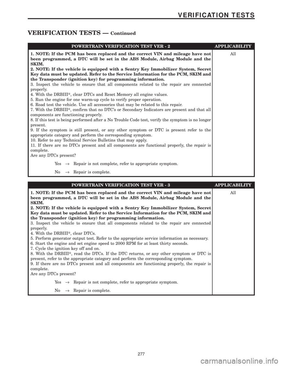
POWERTRAIN VERIFICATION TEST VER - 2 APPLICABILITY
1. NOTE: If the PCM has been replaced and the correct VIN and mileage have not
been programmed, a DTC will be set in the ABS Module, Airbag Module and the
SKIM.
2. NOTE: If the vehicle is equipped with a Sentry Key Immobilizer System, Secret
Key data must be updated. Refer to the Service Information for the PCM, SKIM and
the Transponder (ignition key) for programming information.
3. Inspect the vehicle to ensure that all components related to the repair are connected
properly.
4. With the DRBIIIt, clear DTCs and Reset Memory all engine values.
5. Run the engine for one warm-up cycle to verify proper operation.
6. Road test the vehicle. Use all accessories that may be related to this repair.
7. With the DRBIIIt, confirm that no DTC's or Secondary Indicators are present and that all
components are functioning properly.
8. If this test is being performed after a No Trouble Code test, verify the symptom is no longer
present.
9. If the symptom is still present, or any other symptom or DTC is present refer to the
appropriate category and perform the corresponding symptom.
10. Refer to any Technical Service Bulletins that may apply.
11. If there are no DTCs present and all components are functional properly, the repair is
complete.
Are any DTCs present?All
Ye s®Repair is not complete, refer to appropriate symptom.
No®Repair is complete.
POWERTRAIN VERIFICATION TEST VER - 3 APPLICABILITY
1. NOTE: If the PCM has been replaced and the correct VIN and mileage have not
been programmed, a DTC will be set in the ABS Module, Airbag Module and the
SKIM.
2. NOTE: If the vehicle is equipped with a Sentry Key Immobilizer System, Secret
Key data must be updated. Refer to the Service Information for the PCM, SKIM and
the Transponder (ignition key) for programming information.
3. Inspect the vehicle to ensure that all components related to the repair are connected
properly.
4. With the DRBIIIt, clear DTCs.
5. Perform generator output test. Refer to the appropriate service information as necessary.
6. Start the engine and set engine speed to 2000 RPM for at least thirty seconds.
7. Cycle the ignition key off and on.
8. With the DRBIIIt, read the DTCs. If the DTC returns, or any other symptom or DTC is
present, refer to the appropriate category and perform the corresponding symptom.
9. If there are no DTCs present and all components are functioning properly, the repair is
complete.
Are any DTCs present?All
Ye s®Repair is not complete, refer to appropriate symptom.
No®Repair is complete.
277
VERIFICATION TESTS
VERIFICATION TESTS ÐContinued
Page 4072 of 4284
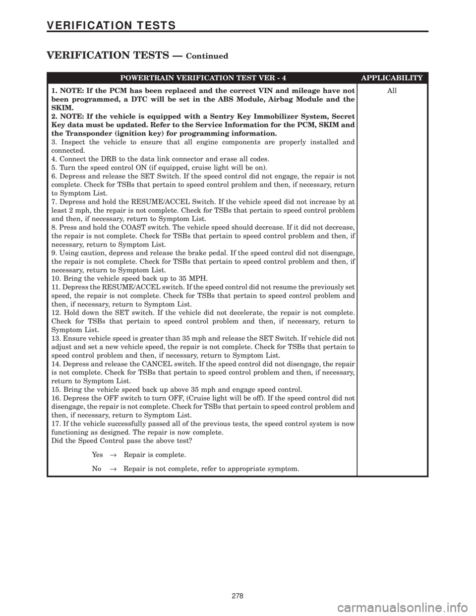
POWERTRAIN VERIFICATION TEST VER - 4 APPLICABILITY
1. NOTE: If the PCM has been replaced and the correct VIN and mileage have not
been programmed, a DTC will be set in the ABS Module, Airbag Module and the
SKIM.
2. NOTE: If the vehicle is equipped with a Sentry Key Immobilizer System, Secret
Key data must be updated. Refer to the Service Information for the PCM, SKIM and
the Transponder (ignition key) for programming information.
3. Inspect the vehicle to ensure that all engine components are properly installed and
connected.
4. Connect the DRB to the data link connector and erase all codes.
5. Turn the speed control ON (if equipped, cruise light will be on).
6. Depress and release the SET Switch. If the speed control did not engage, the repair is not
complete. Check for TSBs that pertain to speed control problem and then, if necessary, return
to Symptom List.
7. Depress and hold the RESUME/ACCEL Switch. If the vehicle speed did not increase by at
least 2 mph, the repair is not complete. Check for TSBs that pertain to speed control problem
and then, if necessary, return to Symptom List.
8. Press and hold the COAST switch. The vehicle speed should decrease. If it did not decrease,
the repair is not complete. Check for TSBs that pertain to speed control problem and then, if
necessary, return to Symptom List.
9. Using caution, depress and release the brake pedal. If the speed control did not disengage,
the repair is not complete. Check for TSBs that pertain to speed control problem and then, if
necessary, return to Symptom List.
10. Bring the vehicle speed back up to 35 MPH.
11. Depress the RESUME/ACCEL switch. If the speed control did not resume the previously set
speed, the repair is not complete. Check for TSBs that pertain to speed control problem and
then, if necessary, return to Symptom List.
12. Hold down the SET switch. If the vehicle did not decelerate, the repair is not complete.
Check for TSBs that pertain to speed control problem and then, if necessary, return to
Symptom List.
13. Ensure vehicle speed is greater than 35 mph and release the SET Switch. If vehicle did not
adjust and set a new vehicle speed, the repair is not complete. Check for TSBs that pertain to
speed control problem and then, if necessary, return to Symptom List.
14. Depress and release the CANCEL switch. If the speed control did not disengage, the repair
is not complete. Check for TSBs that pertain to speed control problem and then, if necessary,
return to Symptom List.
15. Bring the vehicle speed back up above 35 mph and engage speed control.
16. Depress the OFF switch to turn OFF, (Cruise light will be off). If the speed control did not
disengage, the repair is not complete. Check for TSBs that pertain to speed control problem and
then, if necessary, return to Symptom List.
17. If the vehicle successfully passed all of the previous tests, the speed control system is now
functioning as designed. The repair is now complete.
Did the Speed Control pass the above test?All
Ye s®Repair is complete.
No®Repair is not complete, refer to appropriate symptom.
278
VERIFICATION TESTS
VERIFICATION TESTS ÐContinued
Page 4073 of 4284
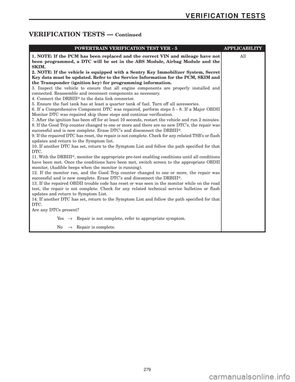
POWERTRAIN VERIFICATION TEST VER - 5 APPLICABILITY
1. NOTE: If the PCM has been replaced and the correct VIN and mileage have not
been programmed, a DTC will be set in the ABS Module, Airbag Module and the
SKIM.
2. NOTE: If the vehicle is equipped with a Sentry Key Immobilizer System, Secret
Key data must be updated. Refer to the Service Information for the PCM, SKIM and
the Transponder (ignition key) for programming information.
3. Inspect the vehicle to ensure that all engine components are properly installed and
connected. Reassemble and reconnect components as necessary.
4. Connect the DRBIIItto the data link connector.
5. Ensure the fuel tank has at least a quarter tank of fuel. Turn off all accessories.
6. If a Comprehensive Component DTC was repaired, perform steps5-8.IfaMajor OBDII
Monitor DTC was repaired skip those steps and continue verification.
7. After the ignition has been off for at least 10 seconds, restart the vehicle and run 2 minutes.
8. If the Good Trip counter changed to one or more and there are no new DTC's, the repair was
successful and is now complete. Erase DTC's and disconnect the DRBIIIt.
9. If the repaired DTC has reset, the repair is not complete. Check for any related TSB's or flash
updates and return to the Symptom list.
10. If another DTC has set, return to the Symptom List and follow the path specified for that
DTC.
11. With the DRBIIIt, monitor the appropriate pre-test enabling conditions until all conditions
have been met. Once the conditions have been met, switch screen to the appropriate OBDII
monitor, (Audible beeps when the monitor is running).
12. If the monitor ran, and the Good Trip counter changed to one or more, the repair was
successful and is now complete. Erase DTC's and disconnect the DRBIIIt.
13. If the repaired OBDII trouble code has reset or was seen in the monitor while on the road
test, the repair is not complete. Check for any related technical service bulletins or flash
updates and return to Symptom List.
14. If another DTC has set, return to the Symptom List and follow the path specified for that
DTC.
Are any DTCs present?All
Ye s®Repair is not complete, refer to appropriate symptom.
No®Repair is complete.
279
VERIFICATION TESTS
VERIFICATION TESTS ÐContinued
Page 4074 of 4284
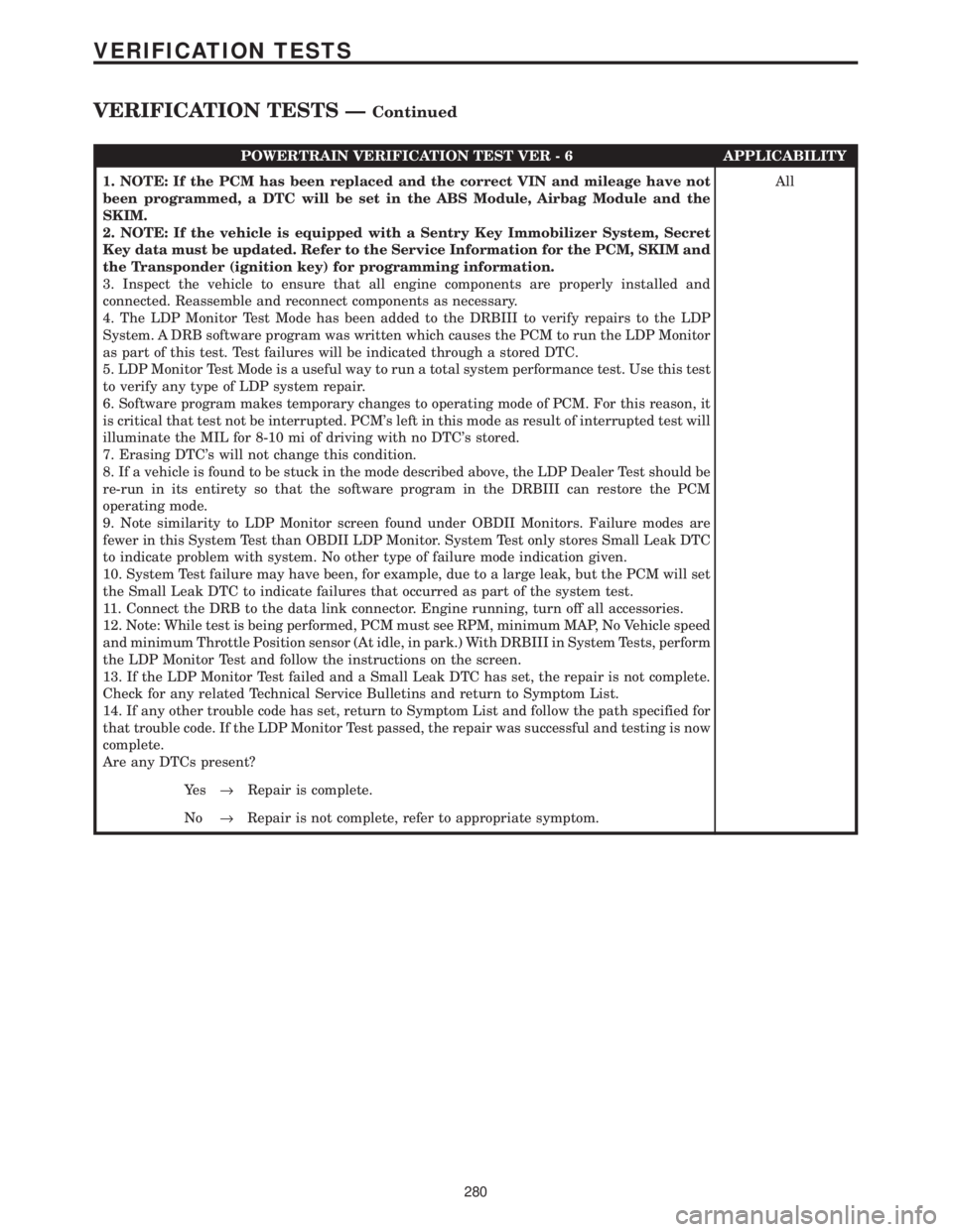
POWERTRAIN VERIFICATION TEST VER - 6 APPLICABILITY
1. NOTE: If the PCM has been replaced and the correct VIN and mileage have not
been programmed, a DTC will be set in the ABS Module, Airbag Module and the
SKIM.
2. NOTE: If the vehicle is equipped with a Sentry Key Immobilizer System, Secret
Key data must be updated. Refer to the Service Information for the PCM, SKIM and
the Transponder (ignition key) for programming information.
3. Inspect the vehicle to ensure that all engine components are properly installed and
connected. Reassemble and reconnect components as necessary.
4. The LDP Monitor Test Mode has been added to the DRBIII to verify repairs to the LDP
System. A DRB software program was written which causes the PCM to run the LDP Monitor
as part of this test. Test failures will be indicated through a stored DTC.
5. LDP Monitor Test Mode is a useful way to run a total system performance test. Use this test
to verify any type of LDP system repair.
6. Software program makes temporary changes to operating mode of PCM. For this reason, it
is critical that test not be interrupted. PCM's left in this mode as result of interrupted test will
illuminate the MIL for 8-10 mi of driving with no DTC's stored.
7. Erasing DTC's will not change this condition.
8. If a vehicle is found to be stuck in the mode described above, the LDP Dealer Test should be
re-run in its entirety so that the software program in the DRBIII can restore the PCM
operating mode.
9. Note similarity to LDP Monitor screen found under OBDII Monitors. Failure modes are
fewer in this System Test than OBDII LDP Monitor. System Test only stores Small Leak DTC
to indicate problem with system. No other type of failure mode indication given.
10. System Test failure may have been, for example, due to a large leak, but the PCM will set
the Small Leak DTC to indicate failures that occurred as part of the system test.
11. Connect the DRB to the data link connector. Engine running, turn off all accessories.
12. Note: While test is being performed, PCM must see RPM, minimum MAP, No Vehicle speed
and minimum Throttle Position sensor (At idle, in park.) With DRBIII in System Tests, perform
the LDP Monitor Test and follow the instructions on the screen.
13. If the LDP Monitor Test failed and a Small Leak DTC has set, the repair is not complete.
Check for any related Technical Service Bulletins and return to Symptom List.
14. If any other trouble code has set, return to Symptom List and follow the path specified for
that trouble code. If the LDP Monitor Test passed, the repair was successful and testing is now
complete.
Are any DTCs present?All
Ye s®Repair is complete.
No®Repair is not complete, refer to appropriate symptom.
280
VERIFICATION TESTS
VERIFICATION TESTS ÐContinued