2001 CHRYSLER VOYAGER airbag off
[x] Cancel search: airbag offPage 449 of 4284

Symptom:
*NO RESPONSE FROM TRANSMISSION CONTROL MODULE
POSSIBLE CAUSES
NO RESPONSE FROM TRANSMISSION CONTROL MODULE
FCM OUTPUT (RUN/ST) CIRCUIT OPEN
IGNITION SWITCH OUTPUT (START) CIRCUIT OPEN
FUSED B(+) CIRCUIT OPEN
GROUND CIRCUIT(S) OPEN
OPEN PCI BUS CIRCUIT
TRANSMISSION CONTROL MODULE
TEST ACTION APPLICABILITY
1 Turn the ignition on.
Note: As soon as one or more module communicates with the DRB, answer
the question.
With the DRB, attempt to communicate with the Airbag Control Module (ACM).
With the DRB, attempt to communicate with the Body Control Module (BCM).
Was the DRB able to I/D or establish communications with either of the modules?All
Ye s®Go To 2
No®Refer to the Body Communication category and perform the
symptom PCI Bus Communication Failure.
Perform 41TE TRANSMISSION VERIFICATION TEST - VER 1.
2 Turn the ignition off.
Disconnect the TCM harness connector.
Turn the ignition on.
Using a 12-volt test light connected to ground, probe the FCM Output (Run/St)
circuit.
Note: The light must illuminate brightly, if it does not light, or lights dimly,
the circuit must be repaired. If there is any doubt, compare the brightness
when testing the circuit, to the brightness when connected directly to the
battery positive post.
Is the test light illuminated?All
Ye s®Go To 3
No®Repair the FCM Output (Run/St) circuit for an open. Refer to the
wiring diagrams location in the Service Information.
Perform 41TE TRANSMISSION VERIFICATION TEST - VER 1.
420
COMMUNICATION
Page 592 of 4284

Symptom:
AIRBAG LAMP CKT SHORT
POSSIBLE CAUSES
EMIC - INTERNAL ERROR
TEST ACTION APPLICABILITY
1 Turn the ignition on.
With the DRBIIIt, record and erase DTC's.
Turn the ignition off, wait 15 seconds, then turn the ignition on.
With the DRBIIIt, read DTCs.
Did the DTC return?All
Ye s®Go To 2
No®Test Complete.
2 If there are no possible causes remaining, view repair. All
Repair
Replace the EMIC.
Perform BODY VERIFICATION TEST - VER 1.
563
INSTRUMENT CLUSTER
Page 593 of 4284

Symptom:
AIRBAG LAMP OPEN
POSSIBLE CAUSES
EMIC - INTERNAL ERROR
TEST ACTION APPLICABILITY
1 Turn the ignition on.
With the DRBIIIt, record and erase DTC's.
Turn the ignition off, wait 15 seconds, then turn the ignition on.
With the DRBIIIt, read DTCs.
Did the DTC return?All
Ye s®Go To 2
No®Test Complete.
2 If there are no possible causes remaining, view repair. All
Repair
Replace the EMIC.
Perform BODY VERIFICATION TEST - VER 1.
564
INSTRUMENT CLUSTER
Page 1018 of 4284
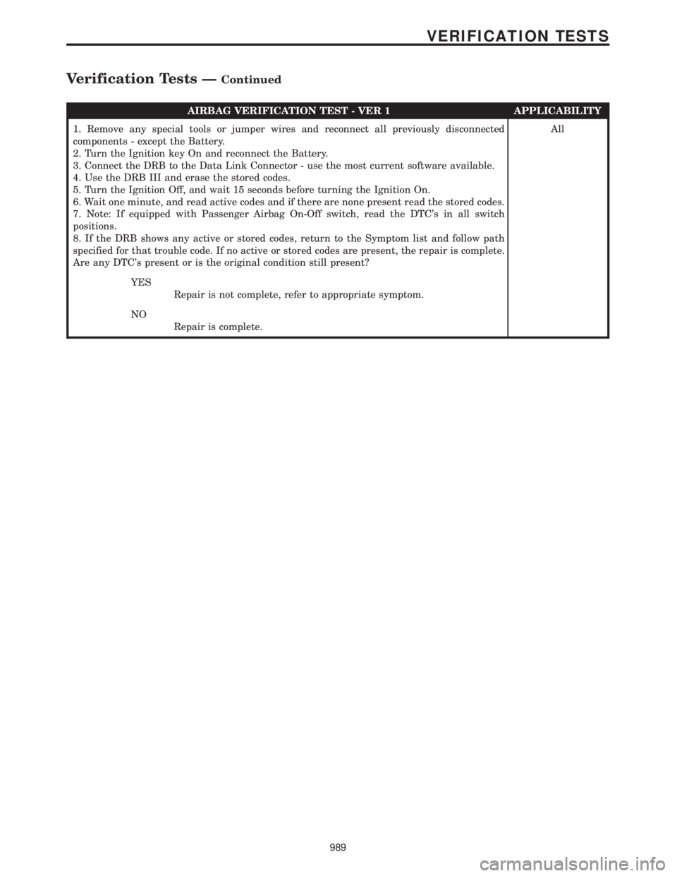
AIRBAG VERIFICATION TEST - VER 1 APPLICABILITY
1. Remove any special tools or jumper wires and reconnect all previously disconnected
components - except the Battery.
2. Turn the Ignition key On and reconnect the Battery.
3. Connect the DRB to the Data Link Connector - use the most current software available.
4. Use the DRB III and erase the stored codes.
5. Turn the Ignition Off, and wait 15 seconds before turning the Ignition On.
6. Wait one minute, and read active codes and if there are none present read the stored codes.
7. Note: If equipped with Passenger Airbag On-Off switch, read the DTC's in all switch
positions.
8. If the DRB shows any active or stored codes, return to the Symptom list and follow path
specified for that trouble code. If no active or stored codes are present, the repair is complete.
Are any DTC's present or is the original condition still present?All
YES
Repair is not complete, refer to appropriate symptom.
NO
Repair is complete.
989
VERIFICATION TESTS
Verification Tests ÐContinued
Page 1021 of 4284
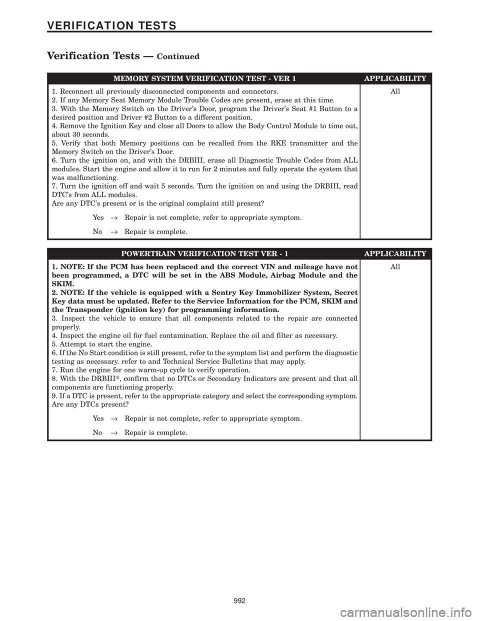
MEMORY SYSTEM VERIFICATION TEST - VER 1 APPLICABILITY
1. Reconnect all previously disconnected components and connectors.
2. If any Memory Seat Memory Module Trouble Codes are present, erase at this time.
3. With the Memory Switch on the Driver's Door, program the Driver's Seat #1 Button to a
desired position and Driver #2 Button to a different position.
4. Remove the Ignition Key and close all Doors to allow the Body Control Module to time out,
about 30 seconds.
5. Verify that both Memory positions can be recalled from the RKE transmitter and the
Memory Switch on the Driver's Door.
6. Turn the ignition on, and with the DRBIII, erase all Diagnostic Trouble Codes from ALL
modules. Start the engine and allow it to run for 2 minutes and fully operate the system that
was malfunctioning.
7. Turn the ignition off and wait 5 seconds. Turn the ignition on and using the DRBIII, read
DTC's from ALL modules.
Are any DTC's present or is the original complaint still present?All
Ye s®Repair is not complete, refer to appropriate symptom.
No®Repair is complete.
POWERTRAIN VERIFICATION TEST VER - 1 APPLICABILITY
1. NOTE: If the PCM has been replaced and the correct VIN and mileage have not
been programmed, a DTC will be set in the ABS Module, Airbag Module and the
SKIM.
2. NOTE: If the vehicle is equipped with a Sentry Key Immobilizer System, Secret
Key data must be updated. Refer to the Service Information for the PCM, SKIM and
the Transponder (ignition key) for programming information.
3. Inspect the vehicle to ensure that all components related to the repair are connected
properly.
4. Inspect the engine oil for fuel contamination. Replace the oil and filter as necessary.
5. Attempt to start the engine.
6. If the No Start condition is still present, refer to the symptom list and perform the diagnostic
testing as necessary. refer to and Technical Service Bulletins that may apply.
7. Run the engine for one warm-up cycle to verify operation.
8. With the DRBIIIt, confirm that no DTCs or Secondary Indicators are present and that all
components are functioning properly.
9. If a DTC is present, refer to the appropriate category and select the corresponding symptom.
Are any DTCs present?All
Ye s®Repair is not complete, refer to appropriate symptom.
No®Repair is complete.
992
VERIFICATION TESTS
Verification Tests ÐContinued
Page 1229 of 4284
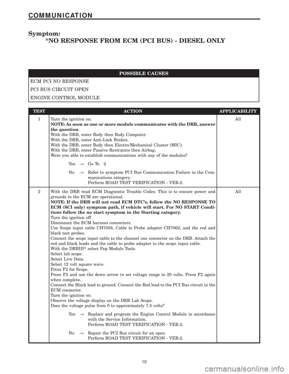
Symptom:
*NO RESPONSE FROM ECM (PCI BUS) - DIESEL ONLY
POSSIBLE CAUSES
ECM PCI NO RESPONSE
PCI BUS CIRCUIT OPEN
ENGINE CONTROL MODULE
TEST ACTION APPLICABILITY
1 Turn the ignition on.
NOTE: As soon as one or more module communicates with the DRB, answer
the question.
With the DRB, enter Body then Body Computer.
With the DRB, enter Anti-Lock Brakes.
With the DRB, enter Body then Electro/Mechanical Cluster (MIC).
With the DRB, enter Passive Restraints then Airbag.
Were you able to establish communications with any of the modules?All
Ye s®Go To 2
No®Refer to symptom PCI Bus Communication Failure in the Com-
munications category.
Perform ROAD TEST VERIFICATION - VER-2.
2 With the DRB read ECM Diagnostic Trouble Codes. This is to ensure power and
grounds to the ECM are operational.
NOTE: If the DRB will not read ECM DTC's, follow the NO RESPONSE TO
ECM (SCI only) symptom path, if vehicle will start. For NO START Condi-
tions follow the no start symptom in the Starting category.
Turn the ignition off.
Disconnect the ECM harness connectors.
Use Scope input cable CH7058, Cable to Probe adapter CH7062, and the red and
black test probes.
Connect the scope input cable to the channel one connector on the DRB. Attach the
red and black leads and the cable to probe adapter to the scope input cable.
With the DRBIIItselect Pep Module Tools.
Select lab scope.
Select Live Data.
Select 12 volt square wave.
Press F2 for Scope.
Press F2 and use the down arrow to set voltage range to 20 volts. Press F2 again
when complete.
Connect the Black lead to ground. Connect the Red lead to the PCI Bus circuit in the
ECM connector.
Turn the ignition on.
Observe the voltage display on the DRB Lab Scope.
Does the voltage pulse from 0 to approximately 7.5 volts?All
Ye s®Replace and program the Engine Control Module in accordance
with the Service Information.
Perform ROAD TEST VERIFICATION - VER-2.
No®Repair the PCI Bus circuit for an open.
Perform ROAD TEST VERIFICATION - VER-2.
10
COMMUNICATION
Page 1821 of 4284
²Engine running at 420 to 480 rpm for 10 sec-
onds
²Oil pressure switch closed to ground for (1 sec-
ond minimum, 2 seconds maximum)
Chime rate: 168 to 192 chimes per minute.
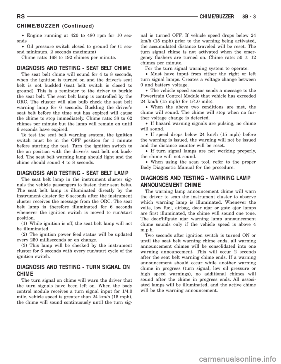
DIAGNOSIS AND TESTING - SEAT BELT CHIME
The seat belt chime will sound for 4 to 8 seconds,
when the ignition is turned on and the driver's seat
belt is not buckled (seat belt switch is closed to
ground). This is a reminder to the driver to buckle
the seat belt. The seat belt lamp is controlled by the
ORC. The cluster will also bulb check the seat belt
warning lamp for 6 seconds. Buckling the driver's
seat belt before the time out has expired will cause
the chime to stop immediately. Chime rate: 38 to 62
chimes per minute but the lamp will remain on until
6 seconds have expired.
To test the seat belt warning system, the ignition
switch must be in the OFF position for 1 minute
before starting the test. Turn the ignition switch to
the on position with the driver's seat belt not buck-
led. The seat belt warning lamp should light and the
chime should sound 4 to 8 seconds.
DIAGNOSIS AND TESTING - SEAT BELT LAMP
The seat belt lamp in the instrument cluster sig-
nals the vehicle passengers to fasten their seat belts.
The seat belt lamp is illuminated directly by the
instrument cluster for 6 seconds after the instrument
cluster receives the message from the ORC. The seat
belt lamp is therefore illuminated for 6 seconds
whenever the ignition switch is moved to run/start
position.
(1) While ignition is off, the seat belt lamp will not
be illuminated.
(2) The ignition power feed status will be updated
every 250 milliseconds or on change.
(3) This lamp will be checked by the instrument
cluster for 6 seconds with every run/start cycle of the
ignition switch.
DIAGNOSIS AND TESTING - TURN SIGNAL ON
CHIME
The turn signal on chime will warn the driver that
the turn signals have been left on. When the body
control module receives a turn signal input for 1/4.0
mile, vehicle speed is greater than 24 km/h (15 mph),
the chime will sound continuously until the turn sig-nal is turned OFF. If vehicle speed drops below 24
km/h (15 mph) prior to the warning being activated,
the accumulated distance traveled will be reset. The
turn signal chime is not activated when the emer-
gency flashers are turned on. Chime rate: 50612
chimes per minute.
For the turn signal warning system to operate:
²Must have input from either the right or left
turn signal lamps. Creates a voltage change between
0 and battery voltage.
²The vehicle speed sensor sends a message to the
Powertrain Control Module that vehicle has exceeded
24 km/h (15 mph) for 1/4.0 mile).
²When the above two conditions are met, the
chime will sound. The chime will stop when no fur-
ther voltage change is detected.
²If hazard warning signals are pulsing, no chime
will sound.
²If speed drops below 24 km/h (15 mph) before
the warning is issued, the warning will not be issued
and the distance counter will be reset.
²If turn signal lamps are not working properly,
the chime will not sound.
²When using the scan tool, refer to the proper
Body Diagnostic Manual for the procedure.
DIAGNOSIS AND TESTING - WARNING LAMP
ANNOUNCEMENT CHIME
The warning lamp announcement chime will warn
the driver to scan the instrument cluster to observe
which warning lamp is illuminated. Whenever the
volts, low fuel, airbag, door ajar or gate ajar lamps
are first illuminated, the chime will sound one tone.
The door/liftgate ajar warning lamp announcement
chime sounds only if the vehicle speed is above 4
m.p.h.
Two seconds after ignition switch is turned ON or
until the seat belt warning chime ends, all warning
announcement chimes will be consolidated into one
warning announcement. This will occur 2 seconds
after the seat belt warning chime ends. If a warning
announcement should occur while another warning
chime in progress (turn signal, low oil pressure or
high speed warnings), no additional chimes will
sound after the chime in progress ends. All associ-
ated lamps will be illuminated, and the active chime
will be the warning announcement.
RSCHIME/BUZZER8B-3
CHIME/BUZZER (Continued)
Page 1927 of 4284
INSTRUMENT CLUSTER
TABLE OF CONTENTS
page page
INSTRUMENT CLUSTER
DESCRIPTION............................1
OPERATION.............................1
DIAGNOSIS AND TESTING..................1
INSTRUMENT CLUSTER..................1
REMOVAL..............................11
INSTALLATION...........................11
CLUSTER LENS
REMOVAL..............................12INSTALLATION...........................12
MECHANICAL TRANSMISSION RANGE
INDICATOR
REMOVAL..............................12
INSTALLATION...........................12
RED BRAKE WARNING INDICATOR
DESCRIPTION...........................12
OPERATION.............................12
INSTRUMENT CLUSTER
DESCRIPTION
The instrumentation gauges are contained in a
subdial assembly within the instrument cluster. The
individual gauges are not serviceable. If one of the
cluster gauges becomes faulty, the entire cluster
would require replacement.
The mechanical instrument cluster with a tachom-
eter is equipped with a electronic vacuum fluorescent
transmission range indicator (PRND3L), odometer,
and trip odometer display.
The mechanical instrument cluster without a
tachometer is equipped with a cable operated trans-
mission range indicator (PRND21) and a vacuum
flourescent odometer display.
The instrument cluster is equipped with the follow-
ing warning lamps.
²Lift Gate Ajar
²Low Fuel Level
²Low Windshield Washer Fluid Level
²Cruise
²Battery Voltage
²Fasten Seat Belt
²Door Ajar
²Headlamp Out
²Coolant Temperature
²Anti-Lock Brake
²Brake
²Airbag
²Traction Control
²Autostick
OPERATION
Refer to the vehicle Owner's Manual for operation
instructions and conditions for the Instrument Clus-
ter Gauges.
DIAGNOSIS AND TESTING - SELF-
DIAGNOSTICS
The instrument clusters are equipped with a self
diagnostic test feature to help identify electronic
problems. Prior to any test, perform the Self-Diag-
nostic Test. The self diagnostic system displays
instrument cluster stored fault codes in the odometer
display, sweeps the gauges to the calibration points,
and bulb checks the warning indicators. When the
key is in the ON position with the engine not run-
ning, the MIL will remain illuminated for regulatory
purposes.
To activate the Self-Diagnostic program:
(1) With the ignition switch in the OFF position,
depress the TRIP ODOMETER RESET button.
(2) Continue to hold the TRIP ODOMETER
RESET button untilSofand a number (software ver-
sion number (i.e.Sof 3.2) appears in the odometer
window (about five seconds) then release the button.
If a fault code is present, the cluster will display it in
the odometer display. When all fault codes have been
displayed, the cluster will displayªendºin the odom-
eter display. Refer to the table to determine what
each trouble code means.
RSINSTRUMENT CLUSTER8J-1