2001 CHRYSLER VOYAGER airbag off
[x] Cancel search: airbag offPage 1957 of 4284
LAMPS/LIGHTING - INTERIOR
TABLE OF CONTENTS
page page
LAMPS/LIGHTING - INTERIOR
SPECIFICATIONS........................17
CENTER CONSOLE LAMP SWITCH
REMOVAL..............................18
INSTALLATION...........................18
CLUSTER ILLUMINATION LAMPS
REMOVAL..............................18
INSTALLATION...........................18
COURTESY LAMP
REMOVAL..............................18
INSTALLATION...........................18
DOME LAMP
REMOVAL..............................18INSTALLATION...........................18
GLOVE BOX LAMP SWITCH
REMOVAL..............................18
INSTALLATION...........................19
LIFTGATE LAMP
REMOVAL..............................19
INSTALLATION...........................19
READING LAMP
REMOVAL..............................19
INSTALLATION...........................20
VANITY LAMP
REMOVAL..............................20
INSTALLATION...........................20
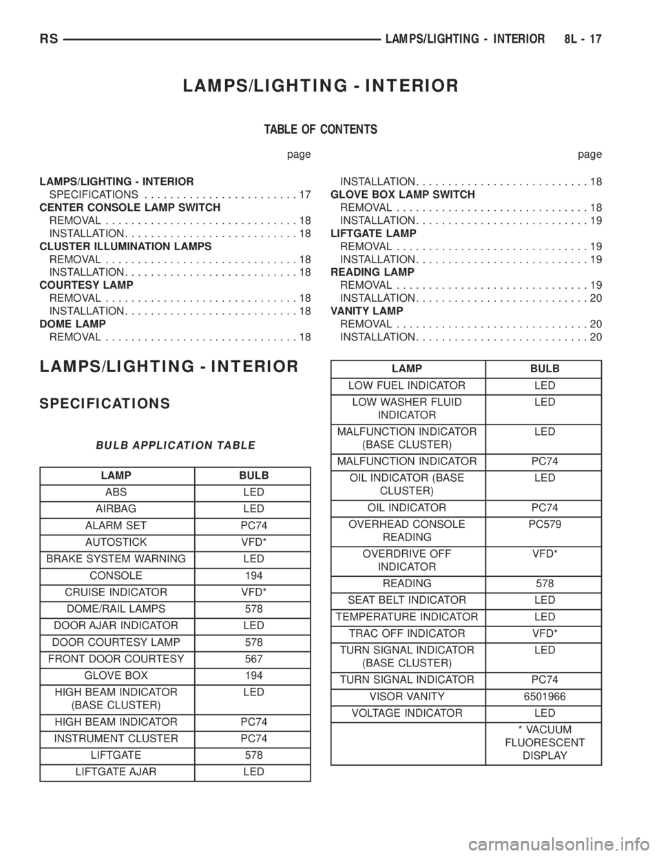
LAMPS/LIGHTING - INTERIOR
SPECIFICATIONS
BULB APPLICATION TABLE
LAMP BULB
ABS LED
AIRBAG LED
ALARM SET PC74
AUTOSTICK VFD*
BRAKE SYSTEM WARNING LED
CONSOLE 194
CRUISE INDICATOR VFD*
DOME/RAIL LAMPS 578
DOOR AJAR INDICATOR LED
DOOR COURTESY LAMP 578
FRONT DOOR COURTESY 567
GLOVE BOX 194
HIGH BEAM INDICATOR
(BASE CLUSTER)LED
HIGH BEAM INDICATOR PC74
INSTRUMENT CLUSTER PC74
LIFTGATE 578
LIFTGATE AJAR LED
LAMP BULB
LOW FUEL INDICATOR LED
LOW WASHER FLUID
INDICATORLED
MALFUNCTION INDICATOR
(BASE CLUSTER)LED
MALFUNCTION INDICATOR PC74
OIL INDICATOR (BASE
CLUSTER)LED
OIL INDICATOR PC74
OVERHEAD CONSOLE
READINGPC579
OVERDRIVE OFF
INDICATORVFD*
READING 578
SEAT BELT INDICATOR LED
TEMPERATURE INDICATOR LED
TRAC OFF INDICATOR VFD*
TURN SIGNAL INDICATOR
(BASE CLUSTER)LED
TURN SIGNAL INDICATOR PC74
VISOR VANITY 6501966
VOLTAGE INDICATOR LED
* VACUUM
FLUORESCENT
DISPLAY
RSLAMPS/LIGHTING - INTERIOR8L-17
Page 2063 of 4284
SPEED CONTROL
TABLE OF CONTENTS
page page
SPEED CONTROL
DESCRIPTION............................1
OPERATION.............................1
DIAGNOSIS AND TESTING..................3
ROAD TEST............................3
SPECIFICATIONS.........................3
CABLE
DESCRIPTION............................3
OPERATION.............................3
REMOVAL...............................3
INSTALLATION............................4
SERVO
DESCRIPTION............................4OPERATION.............................4
REMOVAL...............................4
INSTALLATION............................4
SWITCH
DESCRIPTION............................5
OPERATION.............................5
REMOVAL...............................5
INSTALLATION............................5
VACUUM RESERVOIR
DESCRIPTION............................6
OPERATION.............................6
REMOVAL...............................6
INSTALLATION............................6
SPEED CONTROL
DESCRIPTION
The speed control system is electronically con-
trolled and vacuum operated. The electronic control
is integrated into the powertrain control module,
located on the driver's side under the speed control
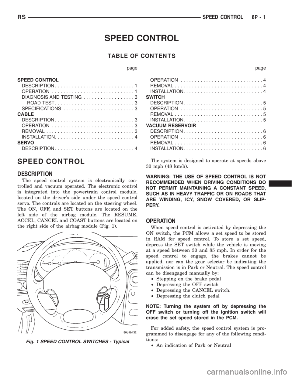
servo. The controls are located on the steering wheel.
The ON, OFF, and SET buttons are located on the
left side of the airbag module. The RESUME,
ACCEL, CANCEL and COAST buttons are located on
the right side of the airbag module (Fig. 1).The system is designed to operate at speeds above
30 mph (48 km/h).
WARNING: THE USE OF SPEED CONTROL IS NOT
RECOMMENDED WHEN DRIVING CONDITIONS DO
NOT PERMIT MAINTAINING A CONSTANT SPEED,
SUCH AS IN HEAVY TRAFFIC OR ON ROADS THAT
ARE WINDING, ICY, SNOW COVERED, OR SLIP-
PERY.
OPERATION
When speed control is activated by depressing the
ON switch, the PCM allows a set speed to be stored
in RAM for speed control. To store a set speed,
depress the SET switch while the vehicle is moving
at a speed between 30 and 85 mph. In order for the
speed control to engage, the brakes cannot be
applied, nor can the gear selector be indicating the
transmission is in Park or Neutral. The speed control
can be disengaged manually by:
²Stepping on the brake pedal
²Depressing the OFF switch
²Depressing the CANCEL switch.
²Depressing the clutch pedal
NOTE: Turning the system off by depressing the
OFF switch or turning off the ignition switch will
erase the set speed stored in the PCM.
For added safety, the speed control system is pro-
grammed to disengage for any of the following condi-
tions:
²An indication of Park or Neutral
Fig. 1 SPEED CONTROL SWITCHES - Typical
RSSPEED CONTROL8P-1
Page 2067 of 4284
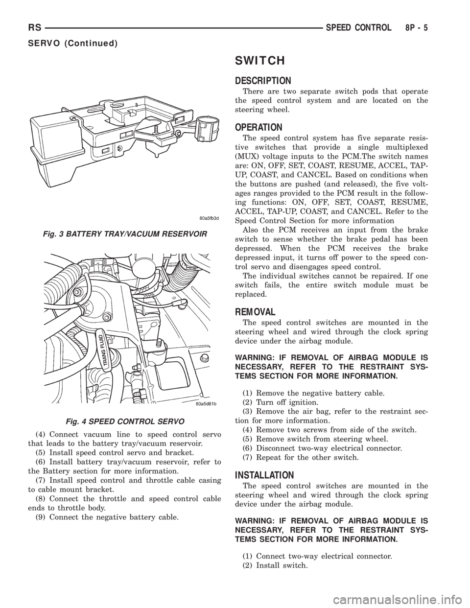
(4) Connect vacuum line to speed control servo
that leads to the battery tray/vacuum reservoir.
(5) Install speed control servo and bracket.
(6) Install battery tray/vacuum reservoir, refer to
the Battery section for more information.
(7) Install speed control and throttle cable casing
to cable mount bracket.
(8) Connect the throttle and speed control cable
ends to throttle body.
(9) Connect the negative battery cable.
SWITCH
DESCRIPTION
There are two separate switch pods that operate
the speed control system and are located on the
steering wheel.
OPERATION
The speed control system has five separate resis-
tive switches that provide a single multiplexed
(MUX) voltage inputs to the PCM.The switch names
are: ON, OFF, SET, COAST, RESUME, ACCEL, TAP-
UP, COAST, and CANCEL. Based on conditions when
the buttons are pushed (and released), the five volt-
ages ranges provided to the PCM result in the follow-
ing functions: ON, OFF, SET, COAST, RESUME,
ACCEL, TAP-UP, COAST, and CANCEL. Refer to the
Speed Control Section for more information
Also the PCM receives an input from the brake
switch to sense whether the brake pedal has been
depressed. When the PCM receives the brake
depressed input, it turns off power to the speed con-
trol servo and disengages speed control.
The individual switches cannot be repaired. If one
switch fails, the entire switch module must be
replaced.
REMOVAL
The speed control switches are mounted in the
steering wheel and wired through the clock spring
device under the airbag module.
WARNING: IF REMOVAL OF AIRBAG MODULE IS
NECESSARY, REFER TO THE RESTRAINT SYS-
TEMS SECTION FOR MORE INFORMATION.
(1) Remove the negative battery cable.
(2) Turn off ignition.
(3) Remove the air bag, refer to the restraint sec-
tion for more information.
(4) Remove two screws from side of the switch.
(5) Remove switch from steering wheel.
(6) Disconnect two-way electrical connector.
(7) Repeat for the other switch.
INSTALLATION
The speed control switches are mounted in the
steering wheel and wired through the clock spring
device under the airbag module.
WARNING: IF REMOVAL OF AIRBAG MODULE IS
NECESSARY, REFER TO THE RESTRAINT SYS-
TEMS SECTION FOR MORE INFORMATION.
(1) Connect two-way electrical connector.
(2) Install switch.
Fig. 3 BATTERY TRAY/VACUUM RESERVOIR
Fig. 4 SPEED CONTROL SERVO
RSSPEED CONTROL8P-5
SERVO (Continued)
Page 2099 of 4284
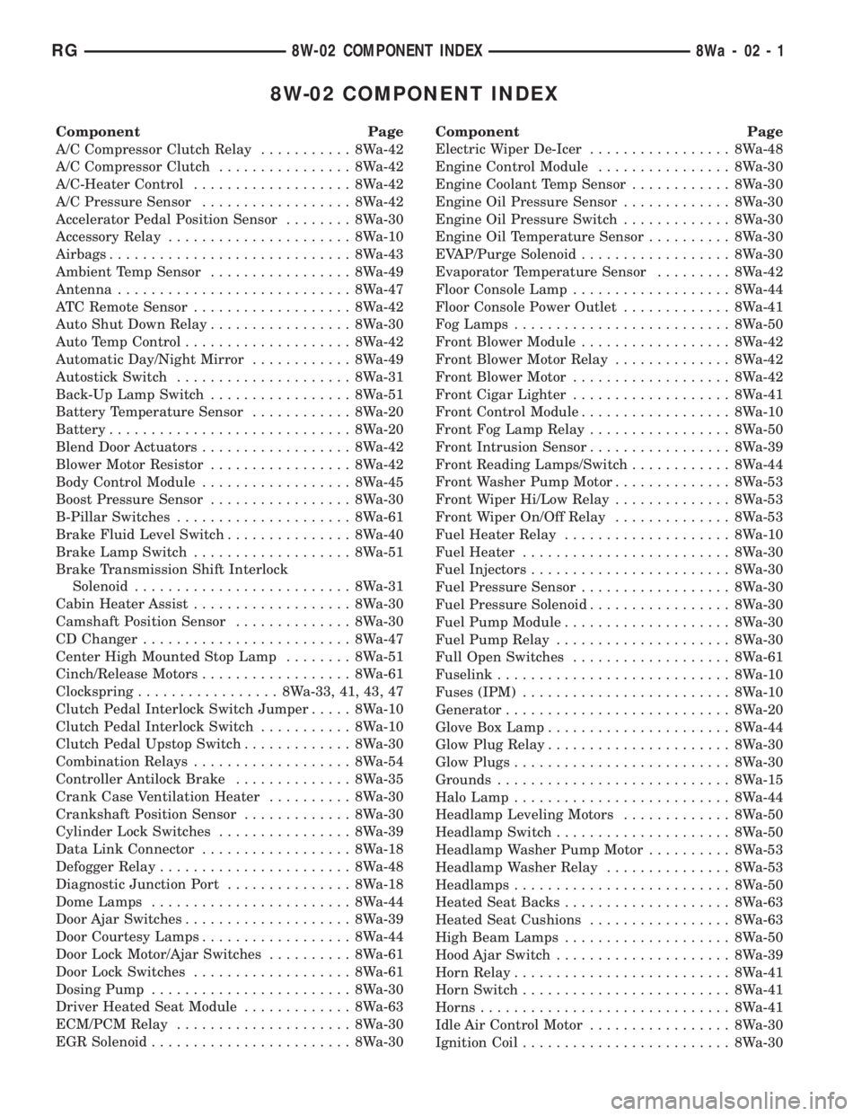
8W-02 COMPONENT INDEX
Component Page
A/C Compressor Clutch Relay........... 8Wa-42
A/C Compressor Clutch................ 8Wa-42
A/C-Heater Control................... 8Wa-42
A/C Pressure Sensor.................. 8Wa-42
Accelerator Pedal Position Sensor........ 8Wa-30
Accessory Relay...................... 8Wa-10
Airbags............................. 8Wa-43
Ambient Temp Sensor................. 8Wa-49
Antenna............................ 8Wa-47
ATC Remote Sensor................... 8Wa-42
Auto Shut Down Relay................. 8Wa-30
Auto Temp Control.................... 8Wa-42
Automatic Day/Night Mirror............ 8Wa-49
Autostick Switch..................... 8Wa-31
Back-Up Lamp Switch................. 8Wa-51
Battery Temperature Sensor............ 8Wa-20
Battery............................. 8Wa-20
Blend Door Actuators.................. 8Wa-42
Blower Motor Resistor................. 8Wa-42
Body Control Module.................. 8Wa-45
Boost Pressure Sensor................. 8Wa-30
B-Pillar Switches..................... 8Wa-61
Brake Fluid Level Switch............... 8Wa-40
Brake Lamp Switch................... 8Wa-51
Brake Transmission Shift Interlock
Solenoid.......................... 8Wa-31
Cabin Heater Assist................... 8Wa-30
Camshaft Position Sensor.............. 8Wa-30
CD Changer......................... 8Wa-47
Center High Mounted Stop Lamp........ 8Wa-51
Cinch/Release Motors.................. 8Wa-61
Clockspring................. 8Wa-33, 41, 43, 47
Clutch Pedal Interlock Switch Jumper..... 8Wa-10
Clutch Pedal Interlock Switch........... 8Wa-10
Clutch Pedal Upstop Switch............. 8Wa-30
Combination Relays................... 8Wa-54
Controller Antilock Brake.............. 8Wa-35
Crank Case Ventilation Heater.......... 8Wa-30
Crankshaft Position Sensor............. 8Wa-30
Cylinder Lock Switches................ 8Wa-39
Data Link Connector.................. 8Wa-18
Defogger Relay....................... 8Wa-48
Diagnostic Junction Port............... 8Wa-18
Dome Lamps........................ 8Wa-44
Door Ajar Switches.................... 8Wa-39
Door Courtesy Lamps.................. 8Wa-44
Door Lock Motor/Ajar Switches.......... 8Wa-61
Door Lock Switches................... 8Wa-61
Dosing Pump........................ 8Wa-30
Driver Heated Seat Module............. 8Wa-63
ECM/PCM Relay..................... 8Wa-30
EGR Solenoid........................ 8Wa-30Component Page
Electric Wiper De-Icer................. 8Wa-48
Engine Control Module................ 8Wa-30
Engine Coolant Temp Sensor............ 8Wa-30
Engine Oil Pressure Sensor............. 8Wa-30
Engine Oil Pressure Switch............. 8Wa-30
Engine Oil Temperature Sensor.......... 8Wa-30
EVAP/Purge Solenoid.................. 8Wa-30
Evaporator Temperature Sensor......... 8Wa-42
Floor Console Lamp................... 8Wa-44
Floor Console Power Outlet............. 8Wa-41
Fog Lamps.......................... 8Wa-50
Front Blower Module.................. 8Wa-42
Front Blower Motor Relay.............. 8Wa-42
Front Blower Motor................... 8Wa-42
Front Cigar Lighter................... 8Wa-41
Front Control Module.................. 8Wa-10
Front Fog Lamp Relay................. 8Wa-50
Front Intrusion Sensor................. 8Wa-39
Front Reading Lamps/Switch............ 8Wa-44
Front Washer Pump Motor.............. 8Wa-53
Front Wiper Hi/Low Relay.............. 8Wa-53
Front Wiper On/Off Relay.............. 8Wa-53
Fuel Heater Relay.................... 8Wa-10
Fuel Heater......................... 8Wa-30
Fuel Injectors........................ 8Wa-30
Fuel Pressure Sensor.................. 8Wa-30
Fuel Pressure Solenoid................. 8Wa-30
Fuel Pump Module.................... 8Wa-30
Fuel Pump Relay..................... 8Wa-30
Full Open Switches................... 8Wa-61
Fuselink............................ 8Wa-10
Fuses (IPM)......................... 8Wa-10
Generator........................... 8Wa-20
Glove Box Lamp...................... 8Wa-44
Glow Plug Relay...................... 8Wa-30
Glow Plugs.......................... 8Wa-30
Grounds............................ 8Wa-15
Halo Lamp.......................... 8Wa-44
Headlamp Leveling Motors............. 8Wa-50
Headlamp Switch..................... 8Wa-50
Headlamp Washer Pump Motor.......... 8Wa-53
Headlamp Washer Relay............... 8Wa-53
Headlamps.......................... 8Wa-50
Heated Seat Backs.................... 8Wa-63
Heated Seat Cushions................. 8Wa-63
High Beam Lamps.................... 8Wa-50
Hood Ajar Switch..................... 8Wa-39
Horn Relay.......................... 8Wa-41
Horn Switch......................... 8Wa-41
Horns.............................. 8Wa-41
Idle Air Control Motor................. 8Wa-30
Ignition Coil......................... 8Wa-30
RG8W-02 COMPONENT INDEX8Wa-02-1
Page 2103 of 4284
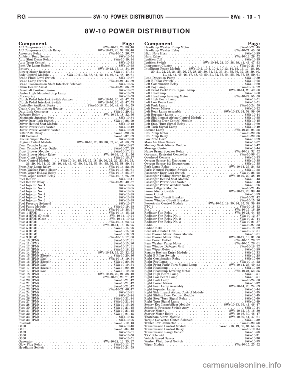
8W-10 POWER DISTRIBUTION
Component PageA/C Compressor Clutch..................8Wa-10-19, 20, 38, 40
A/C Compressor Clutch Relay.............8Wa-10-19, 20, 37, 38, 40
Accessory Relay.......................8Wa-10-15, 26, 57
Ambient Temp Sensor........................8Wa-10-54
Auto Shut Down Relay......................8Wa-10-19, 34
Auto Temp Control.........................8Wa-10-33
Back-Up Lamp Switch........................8Wa-10-58
Battery........................8Wa-10-12, 13, 14, 34, 40
Blower Motor Resistor......................8Wa-10-17, 31
Body Control Module......8Wa-10-21, 33, 38, 41, 42, 44, 46, 47, 48, 49, 61
Brake Fluid Level Switch......................8Wa-10-57
Brake Lamp Switch.....................8Wa-10-21, 44, 59
Brake Transmission Shift Interlock Solenoid.............8Wa-10-55
Cabin Heater Assist.....................8Wa-10-20, 36, 52
Camshaft Position Sensor......................8Wa-10-37
Center High Mounted Stop Lamp..................8Wa-10-59
Clockspring.............................8Wa-10-53
Clutch Pedal Interlock Switch Jumper........8Wa-10-16, 30, 46, 47, 53
Clutch Pedal Interlock Switch............8Wa-10-16, 30, 46, 47, 53
Controller Antilock Brake...........8Wa-10-16, 21, 30, 42, 48, 54, 59
Crank Case Ventilation Heater...................8Wa-10-41
Data Link Connector.......................8Wa-10-29, 61
Defogger Relay......................8Wa-10-17, 18, 32, 56
Diagnostic Junction Port.......................8Wa-10-54
Driver Door Lock Switch.....................8Wa-10-28, 29
Driver Heated Seat Module.....................8Wa-10-42
Driver Power Seat Switch......................8Wa-10-42
Driver Power Window Switch....................8Wa-10-29
ECM/PCM Relay.........................8Wa-10-20, 36
EGR Solenoid..........................8Wa-10-37, 39
Electric Wiper De-Icer........................8Wa-10-28
Engine Control Module........8Wa-10-16, 20, 30, 36, 37, 40, 41, 58, 59
Floor Console Lamp.........................8Wa-10-27
Floor Console Power Outlet...................8Wa-10-27, 29
Front Blower Module......................8Wa-10-17, 31
Front Blower Motor Relay................8Wa-10-16, 17, 31, 56
Front Cigar Lighter.......................8Wa-10-15, 27
Front Control Module . . . 8Wa-10-14, 15, 16, 17, 18, 19, 20, 21, 22, 23, 24, 25,
26, 29, 30, 31, 32, 38, 40, 45, 46, 47, 50, 51, 52, 53, 54. 55, 56, 57, 58, 59, 61
Front Fog Lamp Relay....................8Wa-10-14, 22, 56
Front Washer Pump Motor..................8Wa-10-15, 26, 61
Front Wiper Hi/Low Relay..................8Wa-10-15, 25, 57
Front Wiper On/Off Relay..................8Wa-10-15, 25, 52
Fuel Heater.............................8Wa-10-41
Fuel Heater Relay......................8Wa-10-20, 40, 57
Fuel Injector No. 1..........................8Wa-10-35
Fuel Injector No. 2..........................8Wa-10-35
Fuel Injector No. 3..........................8Wa-10-35
Fuel Injector No. 4..........................8Wa-10-35
Fuel Injector No. 5..........................8Wa-10-35
Fuel Injector No. 6..........................8Wa-10-35
Fuel Pressure Solenoid.......................8Wa-10-37
Fuel Pump Module........................8Wa-10-19, 38
Fuel Pump Relay.......................8Wa-10-19, 38, 57
Fuse 1 (IPM).........................8Wa-10-14, 15, 22
Fuse 2 (IPM) (Diesel).....................8Wa-10-14, 10-24
Fuse 2 (IPM) (Gas)......................8Wa-10-14, 10-23
Fuse 3 (IPM).........................8Wa-10-14, 23, 24
Fuse 4 (IPM).......................8Wa-10-14, 15, 16, 25
Fuse 5 (IPM)...........................8Wa-10-15, 26
Fuse 6 (IPM)...........................8Wa-10-15, 26
Fuse 8 (IPM)...........................8Wa-10-16, 29
Fuse 9 (IPM).........................8Wa-10-16, 17, 30
Fuse 10 (IPM)..........................8Wa-10-17, 31
Fuse 11 (IPM)..........................8Wa-10-15, 26
Fuse 12 (IPM)..........................8Wa-10-17, 31
Fuse 13 (IPM)..........................8Wa-10-18, 32
Fuse 14 (IPM)....................8Wa-10-18, 19, 20, 32, 52
Fuse 15 (IPM) (Diesel)......................8Wa-10-20, 36
Fuse 15 (IPM) (Gas).....................8Wa-10-18, 19, 34
Fuse 16 (IPM) (Diesel)......................8Wa-10-20, 36
Fuse 16 (IPM) (Gas).......................8Wa-10-19, 34
Fuse 17 (IPM) (Diesel)......................8Wa-10-20, 40
Fuse 17 (IPM) (Gas).......................8Wa-10-19, 38
Fuse 18 (IPM)....................8Wa-10-19, 20, 21, 38, 40
Fuse 19 (IPM)......................8Wa-10-19, 20, 21, 42
Fuse 20 (IPM)..........................8Wa-10-21, 42
Fuse 21 (IPM)..........................8Wa-10-21, 42
Fuse 22 (IPM)..........................8Wa-10-21, 42
Fuse 23 (IPM)........................8Wa-10-21, 46, 47
Fuse 24 (IPM)............................8Wa-10-21
Fuse 24 (IPM)............................8Wa-10-44
Fuse 26 (IPM)..........................8Wa-10-21, 44
Fuse 27 (IPM)..........................8Wa-10-21, 44
Fuse 28 (IPM)..........................8Wa-10-15, 26
Fuse 30 (IPM)..........................8Wa-10-21, 45
Fuse 31 (IPM)..........................8Wa-10-21, 45
Fuse 32 (IPM)..........................8Wa-10-21, 45
Fuse 33 (IPM)............................8Wa-10-15
Fuse 33 (IPM)............................8Wa-10-26
Fuselink.............................8Wa-10-12, 13
G100................................8Wa-10-48
G101...............................8Wa-10-34, 40
G103................................8Wa-10-61
G300................................8Wa-10-50
G300................................8Wa-10-51
Generator........................8Wa-10-12, 13, 35, 37
Glow Plug Relay.........................8Wa-10-12, 37
Headlamp Switch........................8Wa-10-24, 55Component PageHeadlamp Washer Pump Motor.................8Wa-10-21, 45
Headlamp Washer Relay...................8Wa-10-21, 45, 56
High Note Horn...........................8Wa-10-29
Horn Relay..........................8Wa-10-16, 29, 52
Ignition Coil.............................8Wa-10-35
Ignition Switch............8Wa-10-16, 21, 30, 38, 39, 41, 46, 47, 53
Instrument Cluster.......................8Wa-10-21, 44
Intelligent Power Module . . 8Wa-10-2, 10-3, 10-4, 10-12, 14, 15, 16, 17, 18, 19,
20, 21, 22, 23, 24, 25, 26, 27, 28, 29, 30, 31, 32, 33, 34, 35, 36, 37, 38, 39, 40,
41, 42, 44, 45, 46, 47, 48, 49, 50, 51, 52, 53, 54, 55, 56, 57, 58, 59, 61
Leak Detection Pump........................8Wa-10-39
Left B-Pillar Switch.........................8Wa-10-28
Left Combination Relay.......................8Wa-10-60
Left Fog Lamp..........................8Wa-10-14, 22
Left Front Park/ Turn Signal Lamp............8Wa-10-14, 23, 49, 58
Left Headlamp............................8Wa-10-50
Left Headlamp Leveling Motor................8Wa-10-24, 55, 58
Left High Beam Lamp........................8Wa-10-51
Left Low Beam Lamp........................8Wa-10-51
Left Park Lamp.........................8Wa-10-24, 58
Left Power Mirror..........................8Wa-10-32
Left Rear Lamp Assembly..............8Wa-10-23, 24, 58, 59, 60
Left Repeater Lamp.........................8Wa-10-44
Left Side Impact Airbag Control Module...............8Wa-10-55
Left Sliding Door Control Module..................8Wa-10-45
Left Stop/ Turn Signal Relay.....................8Wa-10-60
Left Turn Signal Lamp.......................8Wa-10-49
License Lamp........................8Wa-10-23, 24, 58
Lift Pump Motor.........................8Wa-10-20, 36
Lift Pump Relay.........................8Wa-10-20, 36
Low Note Horn...........................8Wa-10-29
Mass Air Flow Sensor........................8Wa-10-37
Memory Seat/ Mirror Module....................8Wa-10-42
Message Center...........................8Wa-10-44
Name Brand Speaker Relay.................8Wa-10-18, 32, 52
Occupant Restraint Controller..................8Wa-10-56, 61
Overhead Console..........................8Wa-10-33
Oxygen Sensor 1/1 Upstream....................8Wa-10-35
Oxygen Sensor 1/2 Downstream...................8Wa-10-35
Park Lamp Relay.....................8Wa-10-14, 23, 24, 52
Park/ Neutral Position Switch....................8Wa-10-58
Passenger Door Lock Switch...................8Wa-10-26, 28
Passenger Folding Mirror Relay.............8Wa-10-19, 20, 38, 40
Passenger Heated Seat Module...................8Wa-10-43
Passenger Power Seat Switch....................8Wa-10-43
Passenger Power Window Switch..................8Wa-10-26
Power Liftgate Module......................8Wa-10-21, 45
Power Mirror Switch...................8Wa-10-19, 20, 39, 40
Power Outlet............................8Wa-10-29
Power Seat Circuit Breaker...................8Wa-10-21, 42
Power Window Circuit Breaker.................8Wa-10-15, 26
Powertrain Control Module........8Wa-10-16, 19, 30, 34, 35, 38, 39, 48
PTC4 ..............................8Wa-10-18, 32
Ptc7.............................8Wa-10-15, 16, 29
Radiator Fan Relay.....................8Wa-10-21, 44, 48
Radiator Fan Relay No. 1....................8Wa-10-12, 37
Radiator Fan Relay No. 2....................8Wa-10-37, 44
Radiator Fan Relay No. 3....................8Wa-10-21, 37
Radio..............................8Wa-10-27, 33
Radio Choke...........................8Wa-10-18, 32
Rear A/C-Heater Unit......................8Wa-10-17, 31
Rear Blower Motor Power Module..................8Wa-10-31
Rear Blower Motor Relay.................8Wa-10-17, 18, 31, 56
Rear Power Outlet......................8Wa-10-15, 26, 27
Rear Washer Pump Motor..................8Wa-10-15, 26, 61
Rear Window Defogger Grid...................8Wa-10-18, 32
Rear Wiper Motor..........................8Wa-10-28
Remote Keyless Entry Module....................8Wa-10-33
Right B-Pillar Switch........................8Wa-10-28
Right Combination Relay......................8Wa-10-60
Right Fog Lamp.........................8Wa-10-14, 22
Right Front Park/ Turn Signal Lamp...........8Wa-10-14, 23, 49, 53
Right Headlamp...........................8Wa-10-50
Right Headlamp Leveling Motor...............8Wa-10-24, 53, 55
Right High Beam Lamp.......................8Wa-10-51
Right Low Beam Lamp.......................8Wa-10-51
Right Park Lamp........................8Wa-10-24, 53
Right Power Mirror.........................8Wa-10-32
Right Rear Lamp Assembly................8Wa-10-14, 23, 24, 59
Right Repeater Lamp........................8Wa-10-44
Right Side Impact Airbag Control Module..............8Wa-10-55
Right Sliding Door Control Module.................8Wa-10-45
Right Stop/ Turn Signal Relay....................8Wa-10-60
Right Turn Signal Lamp.......................8Wa-10-49
Sentry Key Immobilizer Module...........8Wa-10-33, 39, 41, 46, 47
Solenoid/ Pressure Switch Assy...................8Wa-10-34
Starter Motor.......................8Wa-10-12, 13, 16, 30
Starter Motor Relay...................8Wa-10-16, 30, 46, 47
Thatcham Alarm Module.................8Wa-10-39, 41, 47, 61
Torque Converter Clutch Solenoid..................8Wa-10-39
Trailer Tow Connector......................8Wa-10-23, 58
Transmission Control Module...........8Wa-10-16, 19, 30, 34, 54, 55
Transmission Control Relay...................8Wa-10-19, 34
Transmission Range Sensor.....................8Wa-10-58
TXV Solenoid............................8Wa-10-31
Vehicle Speed Sensor........................8Wa-10-36
Washer Fluid Level Switch.....................8Wa-10-53
Wiper Module........................8Wa-10-15, 25, 52
RG8W-10 POWER DISTRIBUTION8Wa-10-1
Page 2936 of 4284
WARNING: SAFETY GOGGLES SHOULD BE WORN
AT ALL TIMES WHEN WORKING ON STEERING
COLUMNS.
CAUTION: Disconnect negative (ground) cable from
the battery before servicing any column compo-
nent.
CAUTION: Do not attempt to remove the pivot pins
to disassemble the tilting mechanism. Damage will
occur.
DIAGNOSIS AND TESTING
For diagnosis of conditions relating to the steering
column (Refer to 19 - STEERING - DIAGNOSIS AND
TESTING) and (Refer to 19 - STEERING - DIAGNO-
SIS AND TESTING).
REMOVAL
To service the steering wheel components or the
airbag (Refer to 8 - ELECTRICAL/RESTRAINTS/
DRIVER AIRBAG - REMOVAL). Follow all WARN-
INGS AND CAUTIONS.
(1) Make sure the front wheels of the vehicle are
in the STRAIGHT AHEAD position before beginning
the column removal procedure.
(2) Disconnect negative (ground) cable from the
battery and isolate cable from battery terminal.
(3) Remove the lower shroud (Refer to 19 -
STEERING/COLUMN/LOWER SHROUD - REMOV-
AL).
(4) Remove the traction off switch.
(5) Remove the upper shroud.
(6) Remove the cluster trim bezel (Refer to 23 -
BODY/INSTRUMENT PANEL/CLUSTER BEZEL -
REMOVAL).(7) Remove the knee blocker (Refer to 23 - BODY/
INSTRUMENT PANEL/STEERING COLUMN
OPENING COVER - REMOVAL).
(8) Remove the parking brake handle link.
(9) Remove the knee blocker reinforcement (Refer
to 23 - BODY/INSTRUMENT PANEL/KNEE
BLOCKER - REMOVAL).
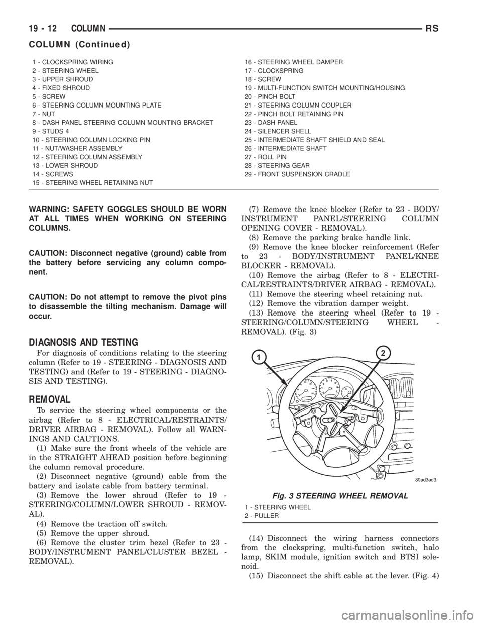
(10) Remove the airbag (Refer to 8 - ELECTRI-
CAL/RESTRAINTS/DRIVER AIRBAG - REMOVAL).
(11) Remove the steering wheel retaining nut.
(12) Remove the vibration damper weight.
(13) Remove the steering wheel (Refer to 19 -
STEERING/COLUMN/STEERING WHEEL -
REMOVAL). (Fig. 3)
(14) Disconnect the wiring harness connectors
from the clockspring, multi-function switch, halo
lamp, SKIM module, ignition switch and BTSI sole-
noid.
(15) Disconnect the shift cable at the lever. (Fig. 4)
1 - CLOCKSPRING WIRING
2 - STEERING WHEEL
3 - UPPER SHROUD
4 - FIXED SHROUD
5 - SCREW
6 - STEERING COLUMN MOUNTING PLATE
7 - NUT
8 - DASH PANEL STEERING COLUMN MOUNTING BRACKET
9 - STUDS 4
10 - STEERING COLUMN LOCKING PIN
11 - NUT/WASHER ASSEMBLY
12 - STEERING COLUMN ASSEMBLY
13 - LOWER SHROUD
14 - SCREWS
15 - STEERING WHEEL RETAINING NUT16 - STEERING WHEEL DAMPER
17 - CLOCKSPRING
18 - SCREW
19 - MULTI-FUNCTION SWITCH MOUNTING/HOUSING
20 - PINCH BOLT
21 - STEERING COLUMN COUPLER
22 - PINCH BOLT RETAINING PIN
23 - DASH PANEL
24 - SILENCER SHELL
25 - INTERMEDIATE SHAFT SHIELD AND SEAL
26 - INTERMEDIATE SHAFT
27 - ROLL PIN
28 - STEERING GEAR
29 - FRONT SUSPENSION CRADLE
Fig. 3 STEERING WHEEL REMOVAL
1 - STEERING WHEEL
2 - PULLER
19 - 12 COLUMNRS
COLUMN (Continued)
Page 2938 of 4284
(16) Install the steering wheel retaining nut.
Tighten the nut to 61 N´m (45 ft. lbs.)
(17) Install the airbag (Refer to 8 - ELECTRICAL/
RESTRAINTS/DRIVER AIRBAG - INSTALLATION).
(18) Install the knee blocker reinforcement (Refer
to 23 - BODY/INSTRUMENT PANEL/KNEE
BLOCKER - INSTALLATION).
(19) Install the parking brake handle link.
(20) Install the knee blocker (Refer to 23 - BODY/
INSTRUMENT PANEL/STEERING COLUMN
OPENING COVER - INSTALLATION).
(21) Install the cluster trim bezel (Refer to 23 -
BODY/INSTRUMENT PANEL/CLUSTER BEZEL -
INSTALLATION).
(22) Install the upper shroud (Refer to 19 -
STEERING/COLUMN/LOWER SHROUD - INSTAL-
LATION).
(23) Install the traction off switch.
(24) Install the lower shroud.
SPECIFICATIONS
COLUMN TORQUE
DESCRIPTION N´mFt.
Lbs.In.
Lbs.
Steering Wheel Retaining
Nut61 45 Ð
Steering Column Mounting
Bracket Attaching Nuts12 Ð 105
Steering Column Coupling
Pinch Bolt28 Ð 250
Steering Column Airbag
Module Attaching Nuts11 Ð 100
KEY/LOCK CYLINDER
DESCRIPTION
The lock cylinder is inserted in the end of the
housing opposite the ignition switch.
OPERATION
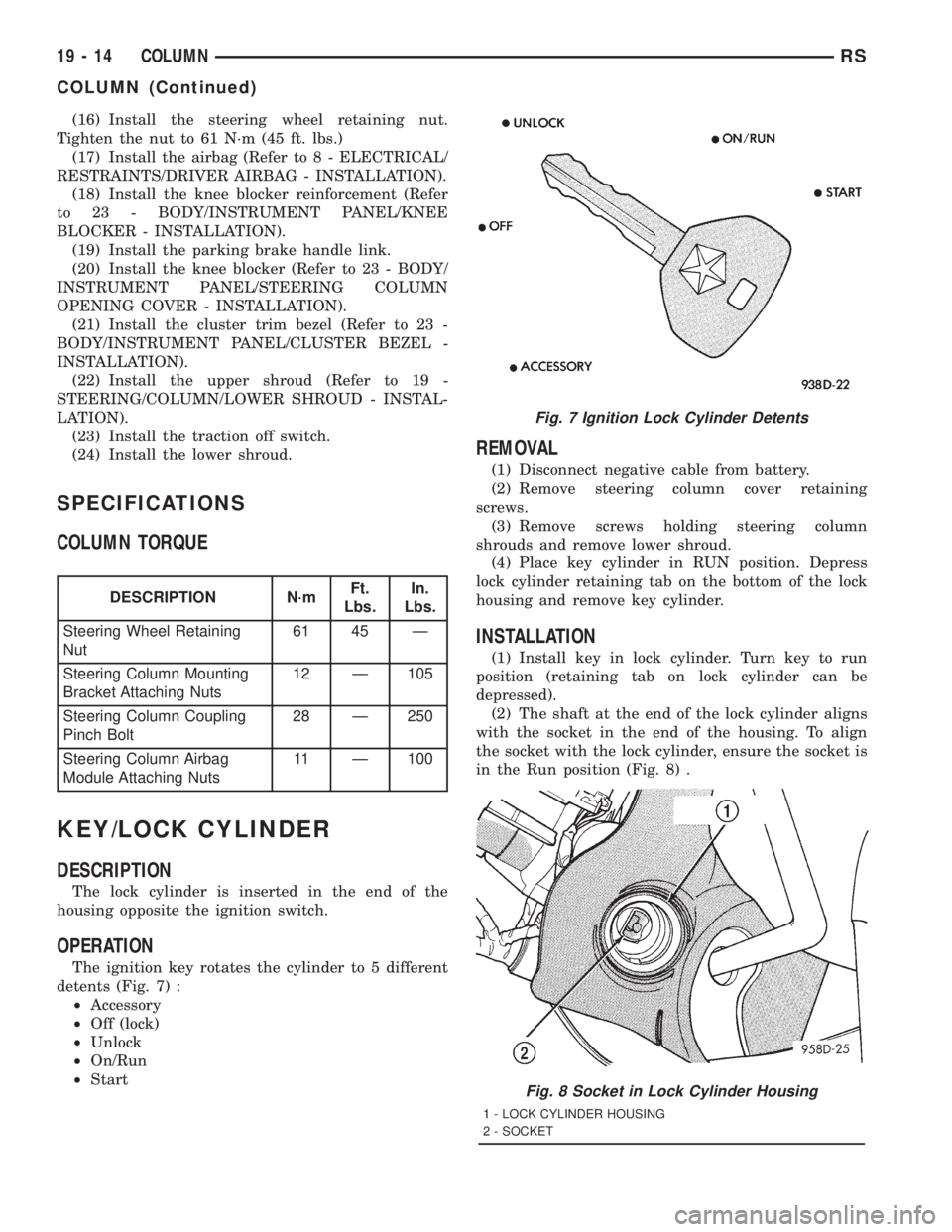
The ignition key rotates the cylinder to 5 different
detents (Fig. 7) :
²Accessory
²Off (lock)
²Unlock
²On/Run
²Start
REMOVAL
(1) Disconnect negative cable from battery.
(2) Remove steering column cover retaining
screws.
(3) Remove screws holding steering column
shrouds and remove lower shroud.
(4) Place key cylinder in RUN position. Depress
lock cylinder retaining tab on the bottom of the lock
housing and remove key cylinder.
INSTALLATION
(1) Install key in lock cylinder. Turn key to run
position (retaining tab on lock cylinder can be
depressed).
(2) The shaft at the end of the lock cylinder aligns
with the socket in the end of the housing. To align
the socket with the lock cylinder, ensure the socket is
in the Run position (Fig. 8) .
Fig. 7 Ignition Lock Cylinder Detents
Fig. 8 Socket in Lock Cylinder Housing
1 - LOCK CYLINDER HOUSING
2 - SOCKET
19 - 14 COLUMNRS
COLUMN (Continued)
Page 3382 of 4284
Before removing the glass, check the availability of
replacement components.
SEATS
Seat modules are made up of a seat frame, seat
cushion, seat back cushion, a covering material, and
the electrical components used for power operation, if
equipped. Some seat systems also contain seat belt
components and supplemental restraint systems.
Seat assemblies transport the occupants in comfort
and safety. Seat assemblies also help position occu-
pants correctly in the event of airbag deployment.
Seat cushions, coverings, and electrical components
are serviceable. Refer to the appropriate group in
this manual.
EXTERIOR COMPONENTS
Exterior sheet metal components make up the
exterior of the vehicle. Some exterior metal systems
are welded assemblies, such as doors and hoods.
Some exterior trim items are made of composite.
The exterior is finished in various metal stampings
and composite moldings. These assemblies give the
vehicle a finished appearance and protect the occu-
pants from the elements. Some components are part
of the energy absorbing system used to protect the
occupants in collisions. The exterior sheet metal is
repairable and adjustable for fit and finish. Welded
and bonded component systems are adjustable as a
system. Trim components made of composite are
stamped with the type of material used.
DaimlerChrysler uses various fasteners to retain
trim items. At times, it is not possible to remove trim
items without damaging the fastener. If it is not pos-
sible to remove an item without damaging a compo-
nent, cut or break the fasteners and use new ones
when installing the component.
SAFETY PRECAUTIONS AND WARNINGS
WARNING:
EYE PROTECTION SHOULD BE USED WHEN SER-
VICING GLASS COMPONENTS. PERSONAL INJURY
CAN RESULT.
USE A OSHA APPROVED BREATHING FILTER
WHEN SPRAYING PAINT OR SOLVENTS IN A CON-
FINED AREA. PERSONAL INJURY CAN RESULT.
AVOID PROLONGED SKIN CONTACT WITH PETRO-
LEUM OR ALCOHOL BASED CLEANING SOLVENTS.
PERSONAL INJURY CAN RESULT.
DO NOT STAND UNDER A HOISTED VEHICLE THAT
IS NOT PROPERLY SUPPORTED ON SAFETY
STANDS. PERSONAL INJURY CAN RESULT.
CAUTION:
When holes must be drilled or punched in an innerbody panel, verify depth of space to the outer body
panel, electrical wiring, or other components. Dam-
age to vehicle can result.
Do not weld exterior panels unless combustible
material on the interior of vehicle is removed from
the repair area. Fire or hazardous conditions, can
result.
Always have a fire extinguisher ready for use when
welding.
Disconnect the negative battery cable clamp when
servicing electrical components that are live when
the ignition is OFF. Damage to electrical system can
result.
Do not use abrasive chemicals or compounds on
painted surfaces. Damage to finish can result.
Do not use harsh alkaline based cleaning solvents
on painted or upholstered surfaces. Damage to fin-
ish or color can result.
Do not hammer or pound on plastic trim panel
when servicing interior trim. Plastic panels can
break.
DIAGNOSIS AND TESTING - WATER LEAKS
Water leaks can be caused by poor sealing,
improper body component alignment, body seam
porosity, missing plugs, or blocked drain holes. Cen-
trifugal and gravitational force can cause water to
drip from a location away from the actual leak point,
making leak detection difficult. All body sealing
points should be water tight in normal wet-driving
conditions. Water flowing downward from the front of
the vehicle should not enter the passenger or luggage
compartment. Moving sealing surfaces will not
always seal water tight under all conditions. At
times, side glass or door seals will allow water to
enter the passenger compartment during high pres-
sure washing or hard driving rain (severe) condi-
tions. Overcompensating on door or glass
adjustments to stop a water leak that occurs under
severe conditions can cause premature seal wear and
excessive closing or latching effort. After completing
a repair, water test vehicle to verify leak has stopped
before returning vehicle to use.
VISUAL INSPECTION BEFORE WATER LEAK TESTS
Verify that floor and body plugs are in place, body
drains are clear, and body components are properly
aligned and sealed. If component alignment or seal-
ing is necessary, refer to the appropriate section of
this group for proper procedures.
WATER LEAK TESTS
WARNING: DO NOT USE ELECTRIC SHOP LIGHTS
OR TOOLS IN WATER TEST AREA. PERSONAL
INJURY CAN RESULT.
23 - 2 BODYRS
BODY (Continued)