Page 216 of 4284
TEST ACTION APPLICABILITY
4WARNING: TURN IGNITION OFF, DISCONNECT THE BATTERY AND WAIT
TWO MINUTES BEFORE PROCEEDING.
WARNING: IF THE RIGHT SIDE IMPACT AIRBAG CONTROL MODULE IS
DROPPED AT ANY TIME, IT MUST BE REPLACED.
If there are no possible causes remaining, view repair.All
Repair
Replace the Right Side Impact Airbag Control Module in accor-
dance with Service Instructions. WARNING: make sure the bat-
tery is disconnected and wait 2 minutes before proceeding.
Perform AIRBAG VERIFICATION TEST - VER 1.
NOTE: When reconnecting airbag system components the Ignition must be
turned off and the Battery must be disconnected.
187
AIRBAG
RIGHT SIACM, SEAT SQUIB SHORT TO GROUND - ACTIVE ÐContinued
Page 217 of 4284
Symptom:
*AIRBAG INDICATOR ON WITHOUT ACTIVE TROUBLE CODES
POSSIBLE CAUSES
AIRBAG INDICATOR ON WITHOUT TROUBLE CODES
INSTRUMENT CLUSTER PROBLEMS
TEST ACTION APPLICABILITY
1 Turn the ignition on.
Make sure that all active DTCS have been repaired before pre forming this
procedure.
With the DRBIII select PASSIVE RESTRAINTS, AIRBAG, MONITOR DISPLAY,
WARNING LAMP STATUS and read the WARNING LAMP STATUS.
Does the DRB show LAMP REQ BY ACM: ON?All
Ye s®Replace the Occupant Restraint Controller in accordance with
Service Instructions. WARNING: make sure the battery is dis-
connected and wait 2 minutes before proceeding.
Perform AIRBAG VERIFICATION TEST - VER 1.
No®Refer to INSTRUMENT CLUSTER CATEGORY symptom list for
problems related to Instrument Cluster.
Perform AIRBAG VERIFICATION TEST - VER 1.
NOTE: When reconnecting Airbag system components, the ignition must be
turned off and the battery must be disconnected.
188
AIRBAG
Page 248 of 4284
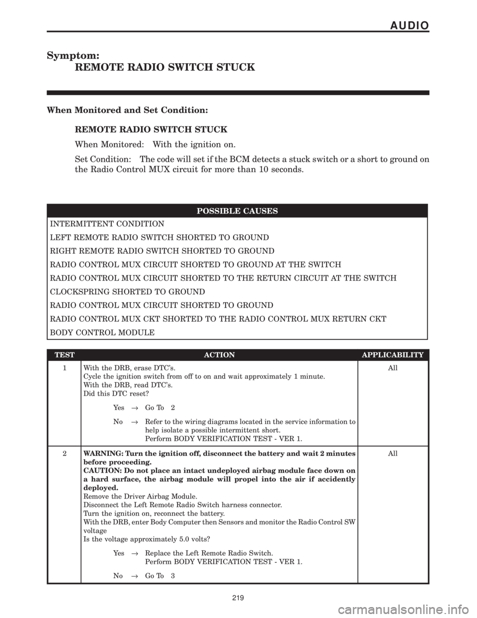
Symptom:
REMOTE RADIO SWITCH STUCK
When Monitored and Set Condition:
REMOTE RADIO SWITCH STUCK
When Monitored: With the ignition on.
Set Condition: The code will set if the BCM detects a stuck switch or a short to ground on
the Radio Control MUX circuit for more than 10 seconds.
POSSIBLE CAUSES
INTERMITTENT CONDITION
LEFT REMOTE RADIO SWITCH SHORTED TO GROUND
RIGHT REMOTE RADIO SWITCH SHORTED TO GROUND
RADIO CONTROL MUX CIRCUIT SHORTED TO GROUND AT THE SWITCH
RADIO CONTROL MUX CIRCUIT SHORTED TO THE RETURN CIRCUIT AT THE SWITCH
CLOCKSPRING SHORTED TO GROUND
RADIO CONTROL MUX CIRCUIT SHORTED TO GROUND
RADIO CONTROL MUX CKT SHORTED TO THE RADIO CONTROL MUX RETURN CKT
BODY CONTROL MODULE
TEST ACTION APPLICABILITY
1 With the DRB, erase DTC's.
Cycle the ignition switch from off to on and wait approximately 1 minute.
With the DRB, read DTC's.
Did this DTC reset?All
Ye s®Go To 2
No®Refer to the wiring diagrams located in the service information to
help isolate a possible intermittent short.
Perform BODY VERIFICATION TEST - VER 1.
2WARNING: Turn the ignition off, disconnect the battery and wait 2 minutes
before proceeding.
CAUTION: Do not place an intact undeployed airbag module face down on
a hard surface, the airbag module will propel into the air if accidently
deployed.
Remove the Driver Airbag Module.
Disconnect the Left Remote Radio Switch harness connector.
Turn the ignition on, reconnect the battery.
With the DRB, enter Body Computer then Sensors and monitor the Radio Control SW
voltage
Is the voltage approximately 5.0 volts?All
Ye s®Replace the Left Remote Radio Switch.
Perform BODY VERIFICATION TEST - VER 1.
No®Go To 3
219
AUDIO
Page 249 of 4284
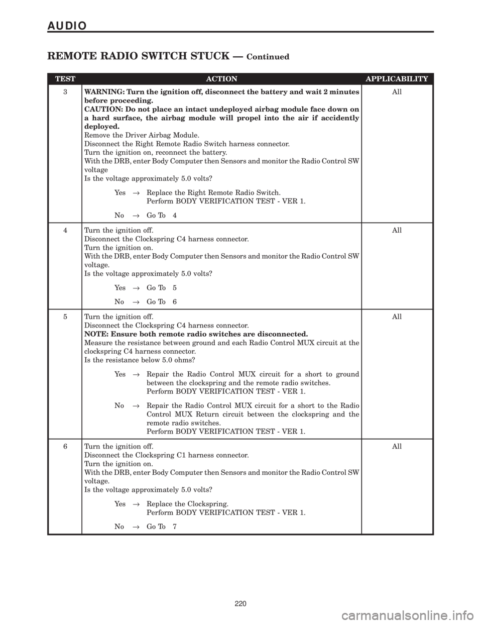
TEST ACTION APPLICABILITY
3WARNING: Turn the ignition off, disconnect the battery and wait 2 minutes
before proceeding.
CAUTION: Do not place an intact undeployed airbag module face down on
a hard surface, the airbag module will propel into the air if accidently
deployed.
Remove the Driver Airbag Module.
Disconnect the Right Remote Radio Switch harness connector.
Turn the ignition on, reconnect the battery.
With the DRB, enter Body Computer then Sensors and monitor the Radio Control SW
voltage
Is the voltage approximately 5.0 volts?All
Ye s®Replace the Right Remote Radio Switch.
Perform BODY VERIFICATION TEST - VER 1.
No®Go To 4
4 Turn the ignition off.
Disconnect the Clockspring C4 harness connector.
Turn the ignition on.
With the DRB, enter Body Computer then Sensors and monitor the Radio Control SW
voltage.
Is the voltage approximately 5.0 volts?All
Ye s®Go To 5
No®Go To 6
5 Turn the ignition off.
Disconnect the Clockspring C4 harness connector.
NOTE: Ensure both remote radio switches are disconnected.
Measure the resistance between ground and each Radio Control MUX circuit at the
clockspring C4 harness connector.
Is the resistance below 5.0 ohms?All
Ye s®Repair the Radio Control MUX circuit for a short to ground
between the clockspring and the remote radio switches.
Perform BODY VERIFICATION TEST - VER 1.
No®Repair the Radio Control MUX circuit for a short to the Radio
Control MUX Return circuit between the clockspring and the
remote radio switches.
Perform BODY VERIFICATION TEST - VER 1.
6 Turn the ignition off.
Disconnect the Clockspring C1 harness connector.
Turn the ignition on.
With the DRB, enter Body Computer then Sensors and monitor the Radio Control SW
voltage.
Is the voltage approximately 5.0 volts?All
Ye s®Replace the Clockspring.
Perform BODY VERIFICATION TEST - VER 1.
No®Go To 7
220
AUDIO
REMOTE RADIO SWITCH STUCK ÐContinued
Page 408 of 4284
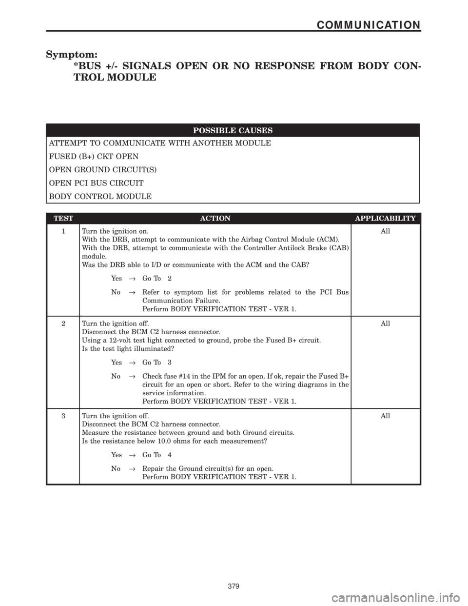
Symptom:
*BUS +/- SIGNALS OPEN OR NO RESPONSE FROM BODY CON-
TROL MODULE
POSSIBLE CAUSES
ATTEMPT TO COMMUNICATE WITH ANOTHER MODULE
FUSED (B+) CKT OPEN
OPEN GROUND CIRCUIT(S)
OPEN PCI BUS CIRCUIT
BODY CONTROL MODULE
TEST ACTION APPLICABILITY
1 Turn the ignition on.
With the DRB, attempt to communicate with the Airbag Control Module (ACM).
With the DRB, attempt to communicate with the Controller Antilock Brake (CAB)
module.
Was the DRB able to I/D or communicate with the ACM and the CAB?All
Ye s®Go To 2
No®Refer to symptom list for problems related to the PCI Bus
Communication Failure.
Perform BODY VERIFICATION TEST - VER 1.
2 Turn the ignition off.
Disconnect the BCM C2 harness connector.
Using a 12-volt test light connected to ground, probe the Fused B+ circuit.
Is the test light illuminated?All
Ye s®Go To 3
No®Check fuse #14 in the IPM for an open. If ok, repair the Fused B+
circuit for an open or short. Refer to the wiring diagrams in the
service information.
Perform BODY VERIFICATION TEST - VER 1.
3 Turn the ignition off.
Disconnect the BCM C2 harness connector.
Measure the resistance between ground and both Ground circuits.
Is the resistance below 10.0 ohms for each measurement?All
Ye s®Go To 4
No®Repair the Ground circuit(s) for an open.
Perform BODY VERIFICATION TEST - VER 1.
379
COMMUNICATION
Page 428 of 4284
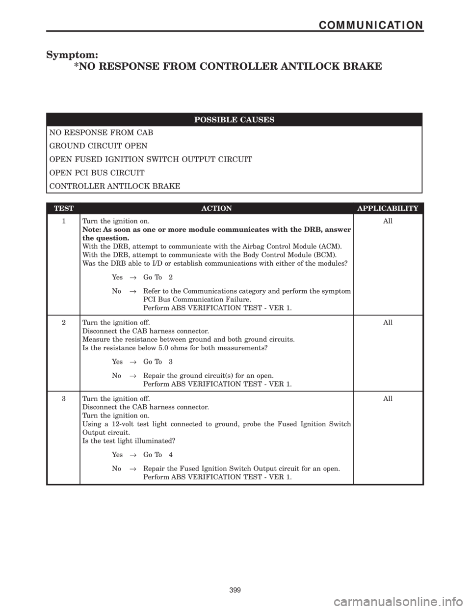
Symptom:
*NO RESPONSE FROM CONTROLLER ANTILOCK BRAKE
POSSIBLE CAUSES
NO RESPONSE FROM CAB
GROUND CIRCUIT OPEN
OPEN FUSED IGNITION SWITCH OUTPUT CIRCUIT
OPEN PCI BUS CIRCUIT
CONTROLLER ANTILOCK BRAKE
TEST ACTION APPLICABILITY
1 Turn the ignition on.
Note: As soon as one or more module communicates with the DRB, answer
the question.
With the DRB, attempt to communicate with the Airbag Control Module (ACM).
With the DRB, attempt to communicate with the Body Control Module (BCM).
Was the DRB able to I/D or establish communications with either of the modules?All
Ye s®Go To 2
No®Refer to the Communications category and perform the symptom
PCI Bus Communication Failure.
Perform ABS VERIFICATION TEST - VER 1.
2 Turn the ignition off.
Disconnect the CAB harness connector.
Measure the resistance between ground and both ground circuits.
Is the resistance below 5.0 ohms for both measurements?All
Ye s®Go To 3
No®Repair the ground circuit(s) for an open.
Perform ABS VERIFICATION TEST - VER 1.
3 Turn the ignition off.
Disconnect the CAB harness connector.
Turn the ignition on.
Using a 12-volt test light connected to ground, probe the Fused Ignition Switch
Output circuit.
Is the test light illuminated?All
Ye s®Go To 4
No®Repair the Fused Ignition Switch Output circuit for an open.
Perform ABS VERIFICATION TEST - VER 1.
399
COMMUNICATION
Page 430 of 4284
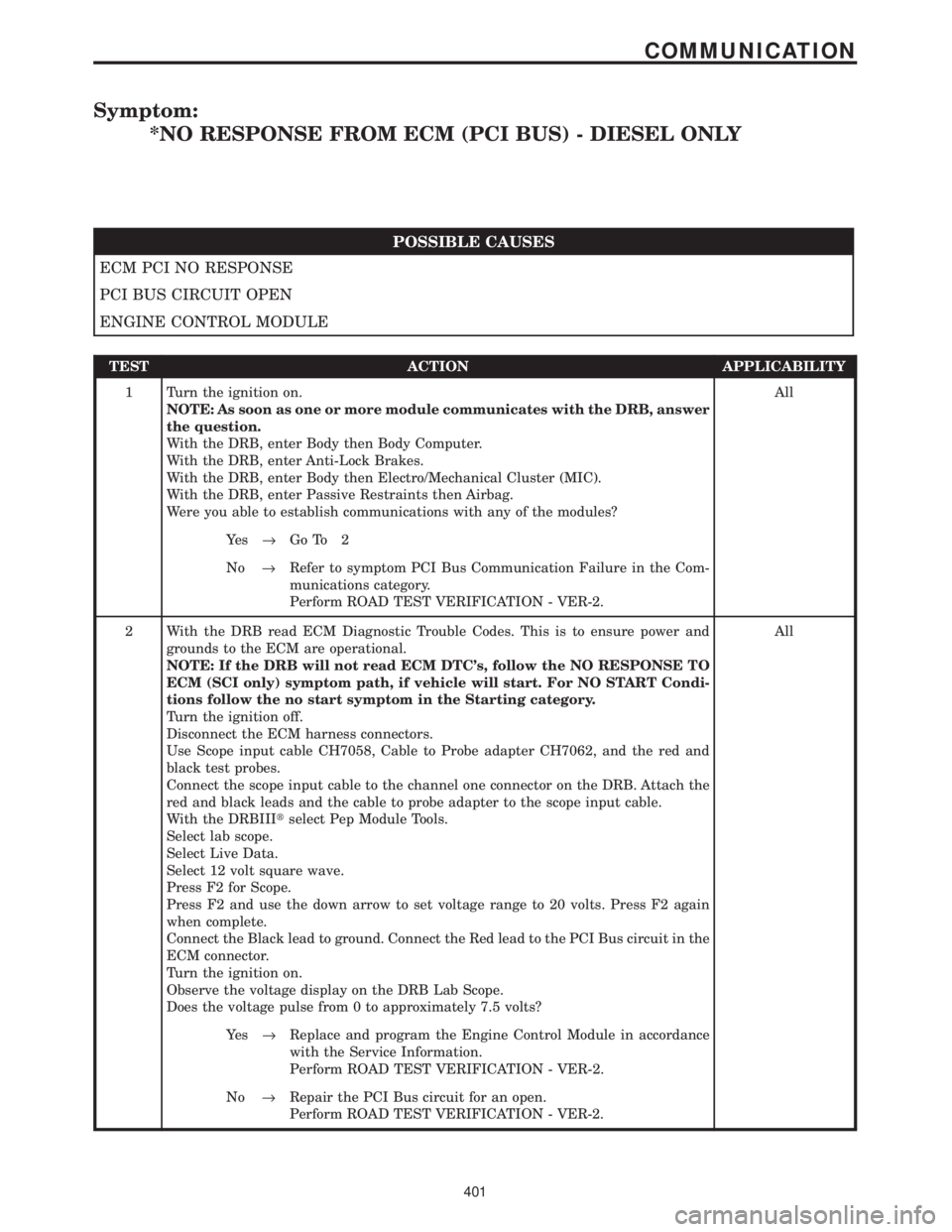
Symptom:
*NO RESPONSE FROM ECM (PCI BUS) - DIESEL ONLY
POSSIBLE CAUSES
ECM PCI NO RESPONSE
PCI BUS CIRCUIT OPEN
ENGINE CONTROL MODULE
TEST ACTION APPLICABILITY
1 Turn the ignition on.
NOTE: As soon as one or more module communicates with the DRB, answer
the question.
With the DRB, enter Body then Body Computer.
With the DRB, enter Anti-Lock Brakes.
With the DRB, enter Body then Electro/Mechanical Cluster (MIC).
With the DRB, enter Passive Restraints then Airbag.
Were you able to establish communications with any of the modules?All
Ye s®Go To 2
No®Refer to symptom PCI Bus Communication Failure in the Com-
munications category.
Perform ROAD TEST VERIFICATION - VER-2.
2 With the DRB read ECM Diagnostic Trouble Codes. This is to ensure power and
grounds to the ECM are operational.
NOTE: If the DRB will not read ECM DTC's, follow the NO RESPONSE TO
ECM (SCI only) symptom path, if vehicle will start. For NO START Condi-
tions follow the no start symptom in the Starting category.
Turn the ignition off.
Disconnect the ECM harness connectors.
Use Scope input cable CH7058, Cable to Probe adapter CH7062, and the red and
black test probes.
Connect the scope input cable to the channel one connector on the DRB. Attach the
red and black leads and the cable to probe adapter to the scope input cable.
With the DRBIIItselect Pep Module Tools.
Select lab scope.
Select Live Data.
Select 12 volt square wave.
Press F2 for Scope.
Press F2 and use the down arrow to set voltage range to 20 volts. Press F2 again
when complete.
Connect the Black lead to ground. Connect the Red lead to the PCI Bus circuit in the
ECM connector.
Turn the ignition on.
Observe the voltage display on the DRB Lab Scope.
Does the voltage pulse from 0 to approximately 7.5 volts?All
Ye s®Replace and program the Engine Control Module in accordance
with the Service Information.
Perform ROAD TEST VERIFICATION - VER-2.
No®Repair the PCI Bus circuit for an open.
Perform ROAD TEST VERIFICATION - VER-2.
401
COMMUNICATION
Page 433 of 4284
Symptom:
*NO RESPONSE FROM FRONT CONTROL MODULE
POSSIBLE CAUSES
ATTEMPT TO COMMUNICATE WITH ANOTHER MODULE
OPEN GROUND CIRCUIT(S)
OPEN PCI BUS CIRCUIT
FRONT CONTROL MODULE
TEST ACTION APPLICABILITY
1 Turn the ignition on.
With the DRB, attempt to communicate with the Airbag Control Module (ACM).
With the DRB, attempt to communicate with the Controller Antilock Brake (CAB)
module.
With the DRB, attempt to communicate with the Body Control Module (BCM).
Was the DRB able to I/D or communicate with any of the modules?All
Ye s®Go To 2
No®Refer to symptom list for problems related to the PCI Bus
Communication Failure.
Perform BODY VERIFICATION TEST - VER 1.
2 Turn the ignition off.
Remove the Front Control Module from the IPM.
Measure the resistance between ground and both Ground circuits.
Is the resistance below 10.0 ohms for each measurement?All
Ye s®Go To 3
No®Repair the Ground circuit(s) for an open.
Perform BODY VERIFICATION TEST - VER 1.
404
COMMUNICATION