Page 1013 of 4284

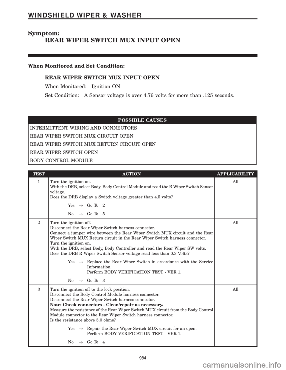
Symptom:
REAR WIPER SWITCH MUX INPUT OPEN
When Monitored and Set Condition:
REAR WIPER SWITCH MUX INPUT OPEN
When Monitored: Ignition ON
Set Condition: A Sensor voltage is over 4.76 volts for more than .125 seconds.
POSSIBLE CAUSES
INTERMITTENT WIRING AND CONNECTORS
REAR WIPER SWITCH MUX CIRCUIT OPEN
REAR WIPER SWITCH MUX RETURN CIRCUIT OPEN
REAR WIPER SWITCH OPEN
BODY CONTROL MODULE
TEST ACTION APPLICABILITY
1 Turn the ignition on.
With the DRB, select Body, Body Control Module and read the R Wiper Switch Sensor
voltage.
Does the DRB display a Switch voltage greater than 4.5 volts?All
Ye s®Go To 2
No®Go To 5
2 Turn the ignition off.
Disconnect the Rear Wiper Switch harness connector.
Connect a jumper wire between the Rear Wiper Switch MUX circuit and the Rear
Wiper Switch MUX Return circuit in the Rear Wiper Switch harness connector.
Turn the ignition on.
With the DRB, select Body, Body Controller and read the Rear Wiper SW volts.
Does the DRB R Wiper Switch Sensor voltage read less than 0.3 Volts?All
Ye s®Replace the Rear Wiper Switch in accordance with the Service
Information.
Perform BODY VERIFICATION TEST - VER 1.
No®Go To 3
3 Turn the ignition off to the lock position.
Disconnect the Body Control Module harness connector.
Disconnect the Rear Wiper Switch harness connector.
Note: Check connectors - Clean/repair as necessary.
Measure the resistance of the Rear Wiper Switch MUX circuit from the Body Control
Module connector to the Rear Wiper Switch harness connector.
Is the resistance above 5.0 ohms?All
Ye s®Repair the Rear Wiper Switch MUX circuit for an open.
Perform BODY VERIFICATION TEST - VER 1.
No®Go To 4
984
WINDSHIELD WIPER & WASHER
Page 1015 of 4284

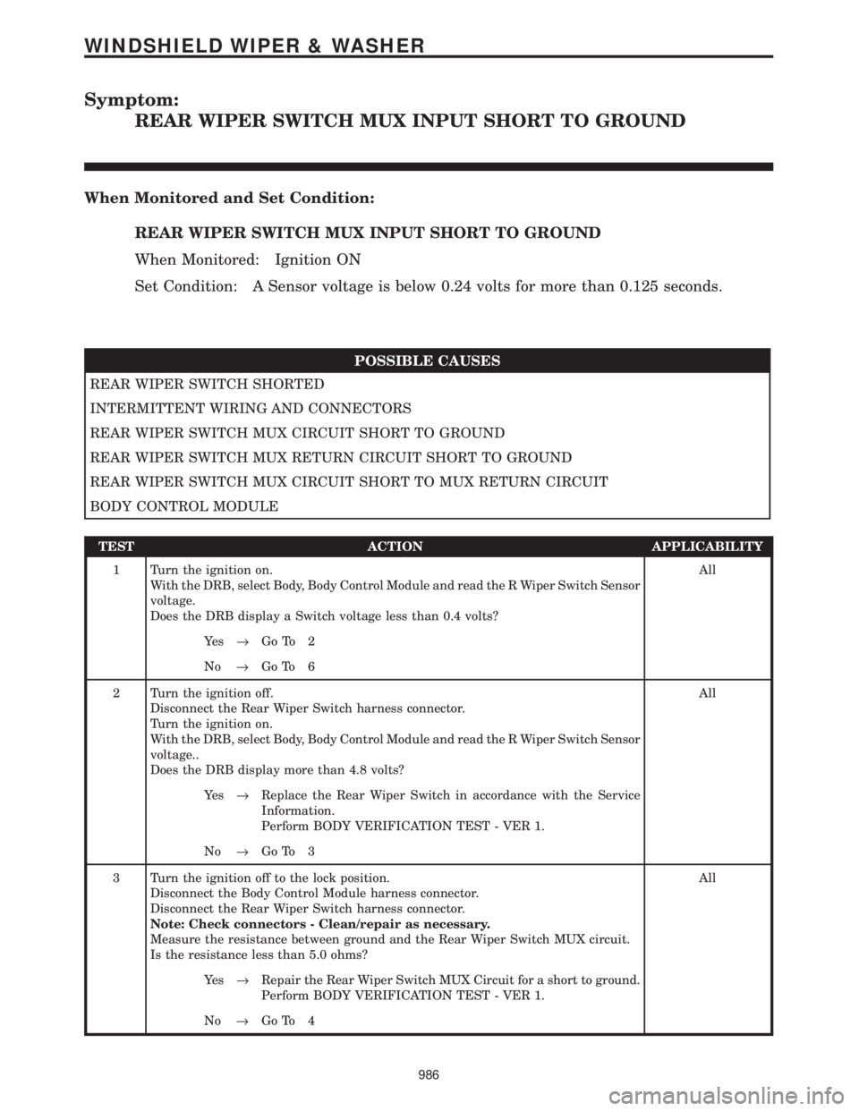
Symptom:
REAR WIPER SWITCH MUX INPUT SHORT TO GROUND
When Monitored and Set Condition:
REAR WIPER SWITCH MUX INPUT SHORT TO GROUND
When Monitored: Ignition ON
Set Condition: A Sensor voltage is below 0.24 volts for more than 0.125 seconds.
POSSIBLE CAUSES
REAR WIPER SWITCH SHORTED
INTERMITTENT WIRING AND CONNECTORS
REAR WIPER SWITCH MUX CIRCUIT SHORT TO GROUND
REAR WIPER SWITCH MUX RETURN CIRCUIT SHORT TO GROUND
REAR WIPER SWITCH MUX CIRCUIT SHORT TO MUX RETURN CIRCUIT
BODY CONTROL MODULE
TEST ACTION APPLICABILITY
1 Turn the ignition on.
With the DRB, select Body, Body Control Module and read the R Wiper Switch Sensor
voltage.
Does the DRB display a Switch voltage less than 0.4 volts?All
Ye s®Go To 2
No®Go To 6
2 Turn the ignition off.
Disconnect the Rear Wiper Switch harness connector.
Turn the ignition on.
With the DRB, select Body, Body Control Module and read the R Wiper Switch Sensor
voltage..
Does the DRB display more than 4.8 volts?All
Ye s®Replace the Rear Wiper Switch in accordance with the Service
Information.
Perform BODY VERIFICATION TEST - VER 1.
No®Go To 3
3 Turn the ignition off to the lock position.
Disconnect the Body Control Module harness connector.
Disconnect the Rear Wiper Switch harness connector.
Note: Check connectors - Clean/repair as necessary.
Measure the resistance between ground and the Rear Wiper Switch MUX circuit.
Is the resistance less than 5.0 ohms?All
Ye s®Repair the Rear Wiper Switch MUX Circuit for a short to ground.
Perform BODY VERIFICATION TEST - VER 1.
No®Go To 4
986
WINDSHIELD WIPER & WASHER
Page 1027 of 4284
8.4.4 ACTUATOR ± FRONT RHD
8.4.5 EVAPORATOR TEMPERATURE SENSOR LHD
C
O
M
P
O
N
E
N
T
L
O
C
A
T
I
O
N
S
998
COMPONENT LOCATIONS
8.4 HEATING & A/C (Continued)
Page 1028 of 4284
8.4.6 EVAPORATOR TEMPERATURE SENSOR RHD
8.4.7 C202 CONNECTOR
C
O
M
P
O
N
E
N
T
L
O
C
A
T
I
O
N
S
999
COMPONENT LOCATIONS
Page 1033 of 4284
8.10 POWER LIFTGATE SYSTEM
8.10.1 MODULE
8.10.2 PINCH SENSORS (TAPE SWITCH)
C
O
M
P
O
N
E
N
T
L
O
C
A
T
I
O
N
S
1004
COMPONENT LOCATIONS
Page 1038 of 4284
8.13.5 FRONT INTRUSION SENSOR
8.13.6 REAR INTRUSION SENSOR
C
O
M
P
O
N
E
N
T
L
O
C
A
T
I
O
N
S
1009
COMPONENT LOCATIONS
Page 1040 of 4284

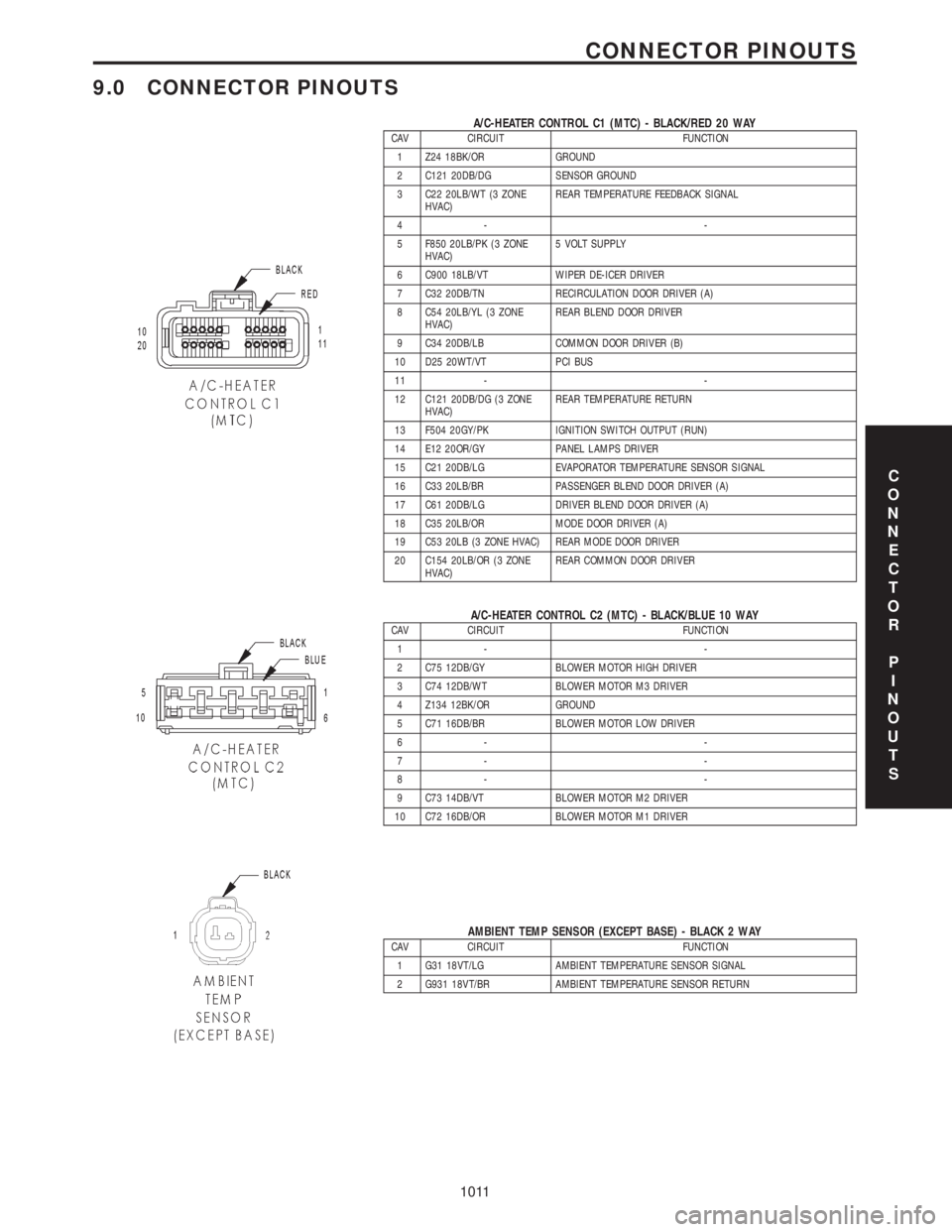
9.0 CONNECTOR PINOUTS
A/C-HEATER CONTROL C1 (MTC) - BLACK/RED 20 WAYCAV CIRCUIT FUNCTION
1 Z24 18BK/OR GROUND
2 C121 20DB/DG SENSOR GROUND
3 C22 20LB/WT (3 ZONE
HVAC)REAR TEMPERATURE FEEDBACK SIGNAL
4- -
5 F850 20LB/PK (3 ZONE
HVAC)5 VOLT SUPPLY
6 C900 18LB/VT WIPER DE-ICER DRIVER
7 C32 20DB/TN RECIRCULATION DOOR DRIVER (A)
8 C54 20LB/YL (3 ZONE
HVAC)REAR BLEND DOOR DRIVER
9 C34 20DB/LB COMMON DOOR DRIVER (B)
10 D25 20WT/VT PCI BUS
11 - -
12 C121 20DB/DG (3 ZONE
HVAC)REAR TEMPERATURE RETURN
13 F504 20GY/PK IGNITION SWITCH OUTPUT (RUN)
14 E12 20OR/GY PANEL LAMPS DRIVER
15 C21 20DB/LG EVAPORATOR TEMPERATURE SENSOR SIGNAL
16 C33 20LB/BR PASSENGER BLEND DOOR DRIVER (A)
17 C61 20DB/LG DRIVER BLEND DOOR DRIVER (A)
18 C35 20LB/OR MODE DOOR DRIVER (A)
19 C53 20LB (3 ZONE HVAC) REAR MODE DOOR DRIVER
20 C154 20LB/OR (3 ZONE
HVAC)REAR COMMON DOOR DRIVER
A/C-HEATER CONTROL C2 (MTC) - BLACK/BLUE 10 WAYCAV CIRCUIT FUNCTION
1- -
2 C75 12DB/GY BLOWER MOTOR HIGH DRIVER
3 C74 12DB/WT BLOWER MOTOR M3 DRIVER
4 Z134 12BK/OR GROUND
5 C71 16DB/BR BLOWER MOTOR LOW DRIVER
6- -
7- -
8- -
9 C73 14DB/VT BLOWER MOTOR M2 DRIVER
10 C72 16DB/OR BLOWER MOTOR M1 DRIVER
AMBIENT TEMP SENSOR (EXCEPT BASE) - BLACK 2 WAYCAV CIRCUIT FUNCTION
1 G31 18VT/LG AMBIENT TEMPERATURE SENSOR SIGNAL
2 G931 18VT/BR AMBIENT TEMPERATURE SENSOR RETURN
C
O
N
N
E
C
T
O
R
P
I
N
O
U
T
S
1011
CONNECTOR PINOUTS
Page 1041 of 4284

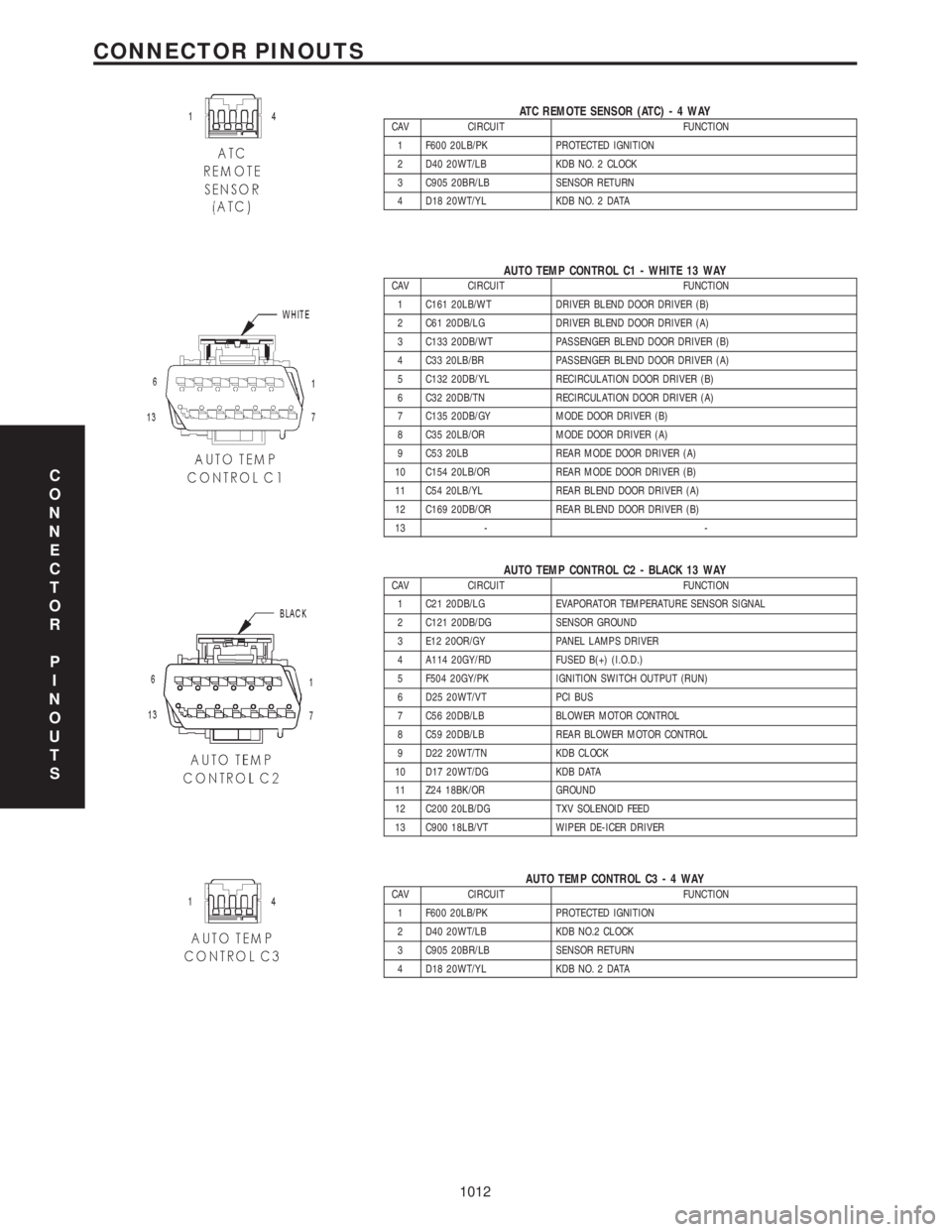
ATC REMOTE SENSOR (ATC)-4WAYCAV CIRCUIT FUNCTION
1 F600 20LB/PK PROTECTED IGNITION
2 D40 20WT/LB KDB NO. 2 CLOCK
3 C905 20BR/LB SENSOR RETURN
4 D18 20WT/YL KDB NO. 2 DATA
AUTO TEMP CONTROL C1 - WHITE 13 WAYCAV CIRCUIT FUNCTION
1 C161 20LB/WT DRIVER BLEND DOOR DRIVER (B)
2 C61 20DB/LG DRIVER BLEND DOOR DRIVER (A)
3 C133 20DB/WT PASSENGER BLEND DOOR DRIVER (B)
4 C33 20LB/BR PASSENGER BLEND DOOR DRIVER (A)
5 C132 20DB/YL RECIRCULATION DOOR DRIVER (B)
6 C32 20DB/TN RECIRCULATION DOOR DRIVER (A)
7 C135 20DB/GY MODE DOOR DRIVER (B)
8 C35 20LB/OR MODE DOOR DRIVER (A)
9 C53 20LB REAR MODE DOOR DRIVER (A)
10 C154 20LB/OR REAR MODE DOOR DRIVER (B)
11 C54 20LB/YL REAR BLEND DOOR DRIVER (A)
12 C169 20DB/OR REAR BLEND DOOR DRIVER (B)
13 - -
AUTO TEMP CONTROL C2 - BLACK 13 WAYCAV CIRCUIT FUNCTION
1 C21 20DB/LG EVAPORATOR TEMPERATURE SENSOR SIGNAL
2 C121 20DB/DG SENSOR GROUND
3 E12 20OR/GY PANEL LAMPS DRIVER
4 A114 20GY/RD FUSED B(+) (I.O.D.)
5 F504 20GY/PK IGNITION SWITCH OUTPUT (RUN)
6 D25 20WT/VT PCI BUS
7 C56 20DB/LB BLOWER MOTOR CONTROL
8 C59 20DB/LB REAR BLOWER MOTOR CONTROL
9 D22 20WT/TN KDB CLOCK
10 D17 20WT/DG KDB DATA
11 Z24 18BK/OR GROUND
12 C200 20LB/DG TXV SOLENOID FEED
13 C900 18LB/VT WIPER DE-ICER DRIVER
AUTO TEMP CONTROL C3-4WAYCAV CIRCUIT FUNCTION
1 F600 20LB/PK PROTECTED IGNITION
2 D40 20WT/LB KDB NO.2 CLOCK
3 C905 20BR/LB SENSOR RETURN
4 D18 20WT/YL KDB NO. 2 DATA
C
O
N
N
E
C
T
O
R
P
I
N
O
U
T
S
1012
CONNECTOR PINOUTS