Page 782 of 4284

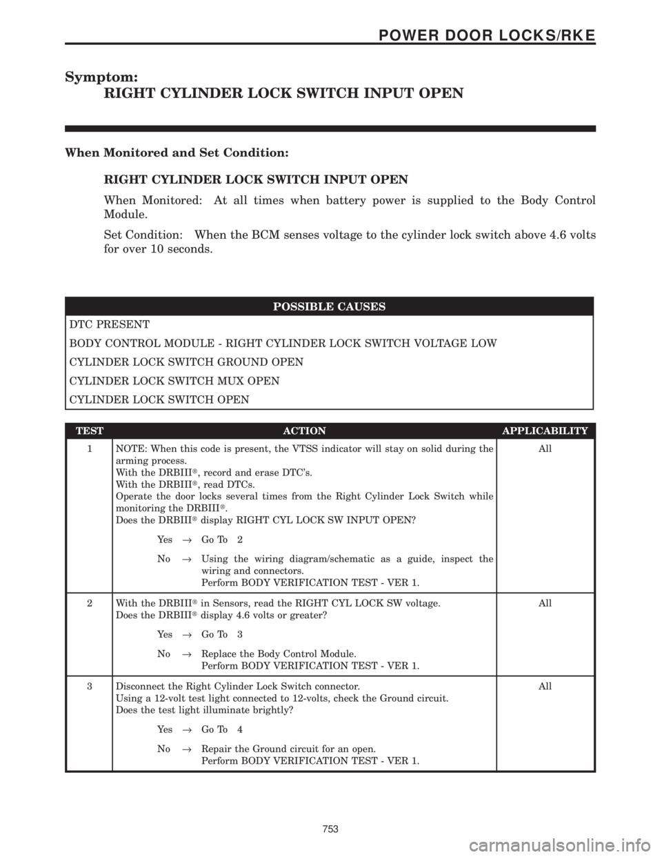
Symptom:
RIGHT CYLINDER LOCK SWITCH INPUT OPEN
When Monitored and Set Condition:
RIGHT CYLINDER LOCK SWITCH INPUT OPEN
When Monitored: At all times when battery power is supplied to the Body Control
Module.
Set Condition: When the BCM senses voltage to the cylinder lock switch above 4.6 volts
for over 10 seconds.
POSSIBLE CAUSES
DTC PRESENT
BODY CONTROL MODULE - RIGHT CYLINDER LOCK SWITCH VOLTAGE LOW
CYLINDER LOCK SWITCH GROUND OPEN
CYLINDER LOCK SWITCH MUX OPEN
CYLINDER LOCK SWITCH OPEN
TEST ACTION APPLICABILITY
1 NOTE: When this code is present, the VTSS indicator will stay on solid during the
arming process.
With the DRBIIIt, record and erase DTC's.
With the DRBIIIt, read DTCs.
Operate the door locks several times from the Right Cylinder Lock Switch while
monitoring the DRBIIIt.
Does the DRBIIItdisplay RIGHT CYL LOCK SW INPUT OPEN?All
Ye s®Go To 2
No®Using the wiring diagram/schematic as a guide, inspect the
wiring and connectors.
Perform BODY VERIFICATION TEST - VER 1.
2 With the DRBIIItin Sensors, read the RIGHT CYL LOCK SW voltage.
Does the DRBIIItdisplay 4.6 volts or greater?All
Ye s®Go To 3
No®Replace the Body Control Module.
Perform BODY VERIFICATION TEST - VER 1.
3 Disconnect the Right Cylinder Lock Switch connector.
Using a 12-volt test light connected to 12-volts, check the Ground circuit.
Does the test light illuminate brightly?All
Ye s®Go To 4
No®Repair the Ground circuit for an open.
Perform BODY VERIFICATION TEST - VER 1.
753
POWER DOOR LOCKS/RKE
Page 784 of 4284

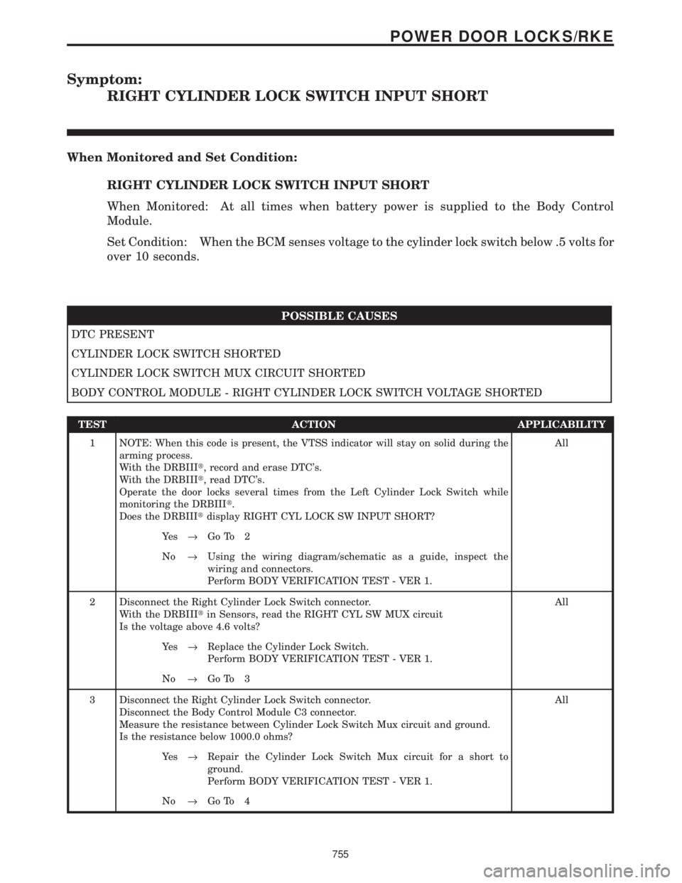
Symptom:
RIGHT CYLINDER LOCK SWITCH INPUT SHORT
When Monitored and Set Condition:
RIGHT CYLINDER LOCK SWITCH INPUT SHORT
When Monitored: At all times when battery power is supplied to the Body Control
Module.
Set Condition: When the BCM senses voltage to the cylinder lock switch below .5 volts for
over 10 seconds.
POSSIBLE CAUSES
DTC PRESENT
CYLINDER LOCK SWITCH SHORTED
CYLINDER LOCK SWITCH MUX CIRCUIT SHORTED
BODY CONTROL MODULE - RIGHT CYLINDER LOCK SWITCH VOLTAGE SHORTED
TEST ACTION APPLICABILITY
1 NOTE: When this code is present, the VTSS indicator will stay on solid during the
arming process.
With the DRBIIIt, record and erase DTC's.
With the DRBIIIt, read DTC's.
Operate the door locks several times from the Left Cylinder Lock Switch while
monitoring the DRBIIIt.
Does the DRBIIItdisplay RIGHT CYL LOCK SW INPUT SHORT?All
Ye s®Go To 2
No®Using the wiring diagram/schematic as a guide, inspect the
wiring and connectors.
Perform BODY VERIFICATION TEST - VER 1.
2 Disconnect the Right Cylinder Lock Switch connector.
With the DRBIIItin Sensors, read the RIGHT CYL SW MUX circuit
Is the voltage above 4.6 volts?All
Ye s®Replace the Cylinder Lock Switch.
Perform BODY VERIFICATION TEST - VER 1.
No®Go To 3
3 Disconnect the Right Cylinder Lock Switch connector.
Disconnect the Body Control Module C3 connector.
Measure the resistance between Cylinder Lock Switch Mux circuit and ground.
Is the resistance below 1000.0 ohms?All
Ye s®Repair the Cylinder Lock Switch Mux circuit for a short to
ground.
Perform BODY VERIFICATION TEST - VER 1.
No®Go To 4
755
POWER DOOR LOCKS/RKE
Page 786 of 4284

Symptom:
RIGHT CYLINDER LOCK SWITCH INPUT STUCK
When Monitored and Set Condition:
RIGHT CYLINDER LOCK SWITCH INPUT STUCK
When Monitored: At all times when battery power is supplied to the Body Control
Module.
Set Condition: When the BCM senses voltage to the cylinder lock switch between 1.3 and
3.25 for over 10 seconds.
POSSIBLE CAUSES
DTC PRESENT
BODY CONTROL MODULE - RIGHT CYLINDER LOCK SWITCH VOLTAGE INCORRECT
RIGHT CYLINDER LOCK SWITCH GROUND OPEN
RIGHT CYLINDER LOCK SWITCH MUX OPEN
CYLINDER LOCK SWITCH STUCK
TEST ACTION APPLICABILITY
1 NOTE: When this code is present, the VTSS indicator will stay on solid during the
arming process.
With the DRBIIIt, record and erase DTC's.
With the DRBIIIt, read DTCs.
Operate the door lock several times from the Right Cylinder Lock Switch while
monitoring the DRBIIIt.
Does the DRBIIItdisplay RIGHT CYL LOCK SW INPUT STUCK?All
Ye s®Go To 2
No®Using the wiring diagram/schematic as a guide, inspect the
wiring and connectors.
Perform BODY VERIFICATION TEST - VER 1.
2 With the DRBIIItin Sensors, read the RIGHT CYL LOCK SW voltage.
Does the DRBIIItdisplay voltage between 1.3 and 3.25 volts?All
Ye s®Go To 3
No®Replace the Body Control Module.
Perform BODY VERIFICATION TEST - VER 1.
3 Disconnect the Right Cylinder Lock Switch connector.
Using a 12-volt test light connected to 12-volts, check the Ground circuit.
Does the test light illuminate brightly?All
Ye s®Go To 4
No®Repair the Ground circuit for an open.
Perform BODY VERIFICATION TEST - VER 1.
757
POWER DOOR LOCKS/RKE
Page 793 of 4284

Symptom:
AMBIENT TEMPERATURE SENSOR CIRCUIT OPEN
When Monitored and Set Condition:
AMBIENT TEMPERATURE SENSOR CIRCUIT OPEN
When Monitored: Whenever the Power Liftgate Module is awake.
Set Condition: If the module senses a resistance above 382K ohms on the Liftgate
Temperature Sensor Signal circuit, this code will set. The normal range for the sensor is
1.2K to 382K ohms. At room temperature (68É F) the resistance will be between 11.2 K and
13.5K ohms.
POSSIBLE CAUSES
DTC PRESENT
POWER LIFTGATE MODULE - TEMPERATURE SENSE OPEN
LIFTGATE TEMPERATURE SENSOR SIGNAL WIRE OPEN
GROUND WIRE OPEN
LIFTGATE TEMPERATURE SENSOR
TEST ACTION APPLICABILITY
1 With the DRBIIIt, record and erase DTC's.
Turn the ignition off, wait 10 seconds, then turn the ignition on.
Operate the liftgate several times.
With the DRBIIIt, read DTCs.
Does the DRBIIItdisplay AMBIENT TEMPERATURE SENSOR CIRCUIT OPEN?All
Ye s®Go To 2
No®Using the wiring diagram/schematic as a guide, inspect the
wiring and connectors for an intermittent condition.
Perform BODY VERIFICATION TEST - VER 1.
2 Remove the power liftgate motor trim panel.
Disconnect the Power Liftgate Module C2 connector.
Measure the resistance of the liftgate Temperature Sensor Signal circuit to the
Ground circuit (cavity 20) in the PLG C2 connector.
Is the resistance between 1.2k and 382K ohms?All
Ye s®Replace the Power Liftgate Module.
Perform BODY VERIFICATION TEST - VER 1.
No®Go To 3
764
POWER DOORS - LIFTGATE
Page 794 of 4284

TEST ACTION APPLICABILITY
3 Remove the power liftgate motor trim panel.
Disconnect the Power Liftgate Module C2 connector.
Disconnect the License Lamp (light bar) connector.
Measure the resistance of the liftgate Temperature Sensor Signal circuit between the
License Lamp connector and the PLG C2 connector.
Is the resistance below 5.0 ohms?All
Ye s®Go To 4
No®Repair the Liftgate Temperature Sensor Signal circuit for an
open.
Perform BODY VERIFICATION TEST - VER 1.
4 Remove the power liftgate motor trim panel.
Disconnect the Power Liftgate Module C2 connector.
Disconnect the License Lamp (light bar) connector.
Measure the resistance of the Ground circuit between the PLG C2 connector (cavity
20) and the License Lamp connector (cavity 8).
Is the resistance below 5.0 ohmsAll
Ye s®Go To 5
No®Repair the Liftgate Temperature Sensor Ground wire for an open.
Perform BODY VERIFICATION TEST - VER 1.
5 If there are no possible causes remaining, view repair. All
Repair
Replace the Liftgate Temperature Sensor (light bar).
Perform BODY VERIFICATION TEST - VER 1.
765
POWER DOORS - LIFTGATE
AMBIENT TEMPERATURE SENSOR CIRCUIT OPEN ÐContinued
Page 795 of 4284

Symptom:
AMBIENT TEMPERATURE SENSOR CIRCUIT SHORT TO GROUND
When Monitored and Set Condition:
AMBIENT TEMPERATURE SENSOR CIRCUIT SHORT TO GROUND
When Monitored: Whenever the Power Liftgate Module is awake.
Set Condition: If the module senses a resistance below 1000 ohms on the Liftgate
Temperature Sensor Signal circuit, this code will set. The normal range for the sensor is
1.2K to 382K ohms. At room temperature (68É F) the resistance will be between 11.2 K and
13.5K ohms.
POSSIBLE CAUSES
DTC PRESENT
LIFTGATE TEMPERATURE SENSOR SIGNAL CIRCUIT SHORT TO GROUND.
POWER LIFTGATE MODULE - TEMP SENSE SHORT TO GROUND
LIFTGATE TEMPERATURE SENSOR SIGNAL WIRE SHORT TO GROUND WIRE
LIFTGATE TEMPERATURE SENSOR
TEST ACTION APPLICABILITY
1 With the DRBIIIt, record and erase DTC's.
Turn the ignition off, wait 10 seconds, then turn the ignition on.
Operate the liftgate several times.
With the DRBIIIt, read DTCs.
Does the DRBIIItdisplay AMBIENT TEMPERATURE SENSOR CIRCUIT SHORT
TO GROUND?All
Ye s®Go To 2
No®Using the wiring diagram/schematic as a guide, inspect the
wiring and connectors for an intermittent condition.
Perform BODY VERIFICATION TEST - VER 1.
2 Remove the power liftgate motor trim panel.
Disconnect the Power Liftgate Module C2 connector.
Measure the resistance between ground and the liftgate Temperature Sensor Signal
circuit.
Is the resistance below 5000.0 ohms?All
Ye s®Repair the Liftgate Temperature Sensor Signal circuit for a short
to ground.
Perform BODY VERIFICATION TEST - VER 1.
No®Go To 3
766
POWER DOORS - LIFTGATE
Page 796 of 4284

TEST ACTION APPLICABILITY
3 Remove the power liftgate motor trim panel.
Disconnect the Power Liftgate Module C2 connector.
Measure the resistance of the liftgate Temperature Sensor Signal circuit to the
Ground circuit (cavity 20) in the PLG C2 connector.
Is the resistance below 1000.0 ohms?All
Ye s®Go To 4
No®Replace the Power Liftgate Module.
Perform BODY VERIFICATION TEST - VER 1.
4 Remove the power liftgate motor trim panel.
Disconnect the Power Liftgate Module C2 connector.
Disconnect the License Lamp (light bar) connector.
Measure the resistance of the liftgate Temperature Sensor Signal circuit to the
Ground circuit (cavity 20) in the PLG C2 connector.
Is the resistance below 1000.0 ohmsAll
Ye s®Repair the Liftgate Temperature Sensor Signal wire for a short to
the Ground wire.
Perform BODY VERIFICATION TEST - VER 1.
No®Replace the Liftgate Temperature Sensor (light bar).
Perform BODY VERIFICATION TEST - VER 1.
767
POWER DOORS - LIFTGATE
AMBIENT TEMPERATURE SENSOR CIRCUIT SHORT TO GROUND Ð
Continued
Page 822 of 4284

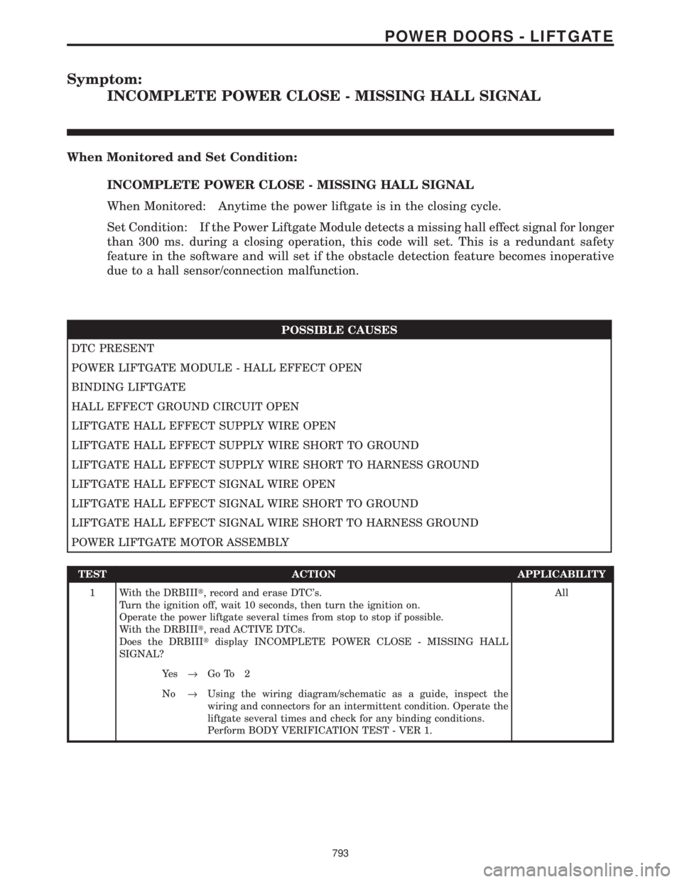
Symptom:
INCOMPLETE POWER CLOSE - MISSING HALL SIGNAL
When Monitored and Set Condition:
INCOMPLETE POWER CLOSE - MISSING HALL SIGNAL
When Monitored: Anytime the power liftgate is in the closing cycle.
Set Condition: If the Power Liftgate Module detects a missing hall effect signal for longer
than 300 ms. during a closing operation, this code will set. This is a redundant safety
feature in the software and will set if the obstacle detection feature becomes inoperative
due to a hall sensor/connection malfunction.
POSSIBLE CAUSES
DTC PRESENT
POWER LIFTGATE MODULE - HALL EFFECT OPEN
BINDING LIFTGATE
HALL EFFECT GROUND CIRCUIT OPEN
LIFTGATE HALL EFFECT SUPPLY WIRE OPEN
LIFTGATE HALL EFFECT SUPPLY WIRE SHORT TO GROUND
LIFTGATE HALL EFFECT SUPPLY WIRE SHORT TO HARNESS GROUND
LIFTGATE HALL EFFECT SIGNAL WIRE OPEN
LIFTGATE HALL EFFECT SIGNAL WIRE SHORT TO GROUND
LIFTGATE HALL EFFECT SIGNAL WIRE SHORT TO HARNESS GROUND
POWER LIFTGATE MOTOR ASSEMBLY
TEST ACTION APPLICABILITY
1 With the DRBIIIt, record and erase DTC's.
Turn the ignition off, wait 10 seconds, then turn the ignition on.
Operate the power liftgate several times from stop to stop if possible.
With the DRBIIIt, read ACTIVE DTCs.
Does the DRBIIItdisplay INCOMPLETE POWER CLOSE - MISSING HALL
SIGNAL?All
Ye s®Go To 2
No®Using the wiring diagram/schematic as a guide, inspect the
wiring and connectors for an intermittent condition. Operate the
liftgate several times and check for any binding conditions.
Perform BODY VERIFICATION TEST - VER 1.
793
POWER DOORS - LIFTGATE