Page 418 of 4770
Check each circuit found to be a possible cause of trouble according to the results of the check in
.The numbers in the table below show the order in which the checks should be performed.
Does malfunction disappear when a good main oxygen sensor is
installed? Check each item found to be a possible cause of problem.
Check compression (See page EG1±23).
Check and replace engine control module.
Characteristics deviation
in engine coolant temp. sensor.
Characteristics deviation in
manifold absolute pressure sensor.
Replace main oxygen sensor.
Main oxygen sensor
signal continue at 5.0 V.
x: Except California specification vehicles.Characteristics deviation
in intake air temp. sensor. Main oxygen sensor
signal is normal.
Repair or replace.
Repair or replace.
Possible Cause
Injector circuit
Valve timing
Fuel system Air leakageSee page
IG±6, 26*
YES
EG1±410
EG1±360 EG1±419
EG1±372 EG1±173
EG1±356 Misfire
EG1±36
± 5S±FE ENGINECIRCUIT INSPECTIONEG1±368
Page 419 of 4770
CIRCUIT DESCRIPTION
The sub oxygen sensor is installed on the exhaust pipe. Its construction and operation is the same as
the main oxygen sensor on page EG1±352.
Main oxygen sensor signal is 0.45 V or more
and sub oxygen sensor signal is 0.45 V or less
under conditions (a) and (b).
(2 trip detection logic) *
(a) Engine coolant temp. : 80�C (1 76�F) or more.
(b) Accel. pedal : Fully depressed for 2 sec. or more.wOpen or short in sub oxygen sensor circuit.
wSub oxygen sensor
wECM Diagnostic Trouble Code Detecting Condition
* : See page EG1±307.
Trouble Area
DTC 27 Sub Oxygen Sensor Circuit
DTC No.
± 5S±FE ENGINECIRCUIT INSPECTIONEG1±369
Page 427 of 4770
DIAGNOSTIC CHART
HINT: If diagnostic trouble codes ª22º (engine coolant temperature sensor circuit), ª24º (intake air
temperature sensor circuit),ª31º (manifold absolute pressure sensor circuit) and ª41º (throttle posi±
tion sensor circuit) are output simultaneously, E2 (sensor ground) may be open.
Check for open and short in harness and
connector between throttle position sensor and
ECM.Check for momentary interruption
(See page EG1±309).
Adjust or replace throttle position
sensor.
Repair or replace harness or
connector. Check operation for throttle position sensor.Check voltage of throttle position sensor.
WIRING DIAGRAM
Check and replace ECM.
± 5S±FE ENGINECIRCUIT INSPECTIONEG1±377
Page 428 of 4770

INSPECTION PROCEDURE
HINT: If diagnostic trouble code ª22º (engine coolant temperature sensor circuit), ª24º (intake air
temperature sensor circuit), ª31º (manifold absolute pressure sensor circuit) and ª41 ª (throttle
position sensor circuit) are output simultaneously, E2 (sensor ground) may be open.
(1) Remove glove compartment.
(See page EG1±234).
(2) Disconnect the vacuum hose from the throt±
tle body, then apply vacuum to the throttle
opener (See page EG1±204).
(3) Turn ignition switch ON.
Measure voltage between terminals VTA, IDL and
E2 of engine control module connector when the
throttle valve is opened gradually from the closed
condition.
Check voltage between terminals VTA, IDL and E2 of engine
control module connector.
The voltage should increase steadily in propor±
tion to the throttle valve opening angle.
Check for momentary interruption
(See page EG1±309).
Throttle Valve
Fully Closed
Fully OpenVTA ± E2 Terminal
IDL ± E2
± 5S±FE ENGINECIRCUIT INSPECTIONEG1±378
Page 430 of 4770

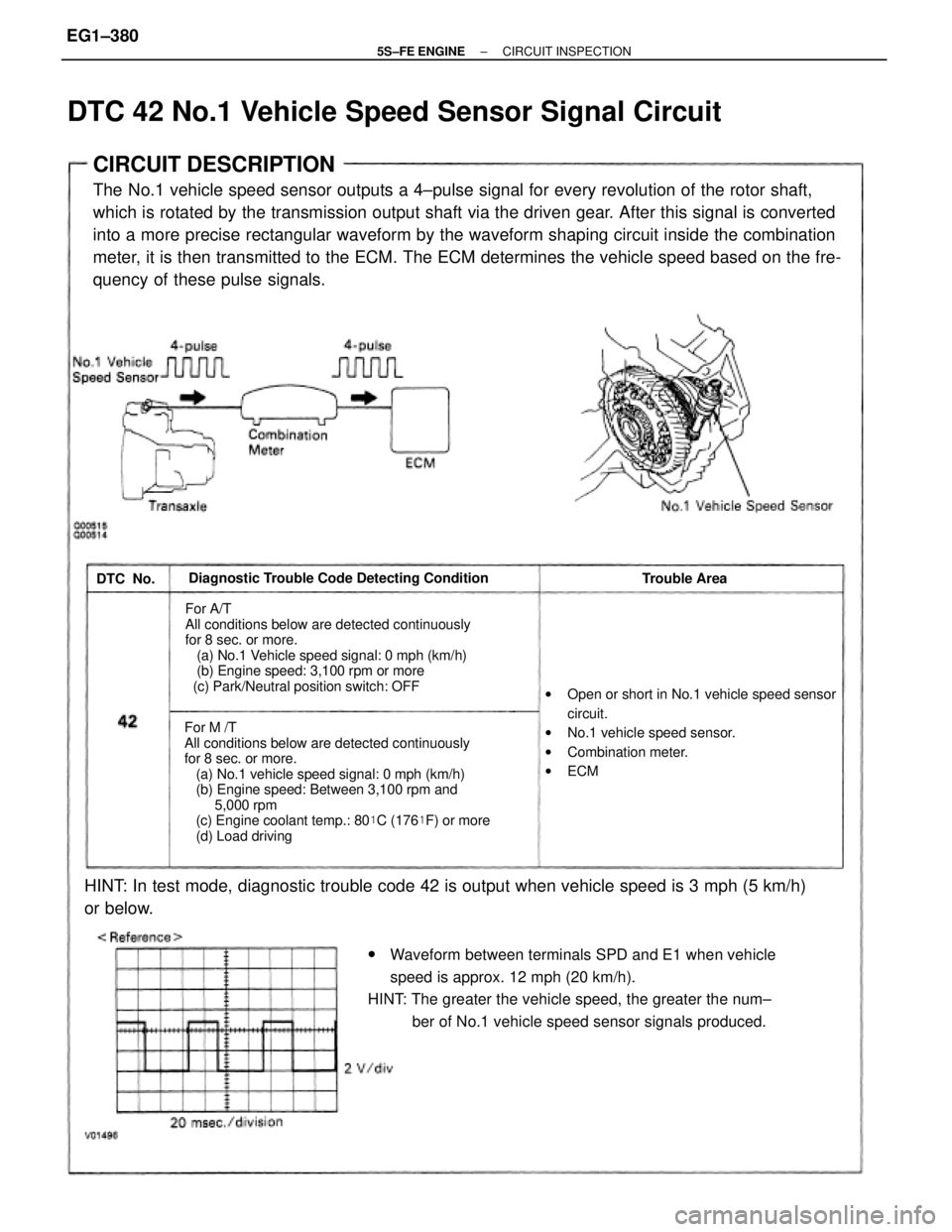
CIRCUIT DESCRIPTION
The No.1 vehicle speed sensor outputs a 4±pulse signal for every revolution of the rotor shaft,
which is rotated by the transmission output shaft via the driven gear. After this signal is converted
into a more precise rectangular waveform by the waveform shaping circuit inside the combination
meter, it is then transmitted to the ECM. The ECM determines the vehicle speed based on the fre-
quency of these pulse signals.
For M /T
All conditions below are detected continuously
for 8 sec. or more.
(a) No.1 vehicle speed signal: 0 mph (km/h)
(b) Engine speed: Between 3,100 rpm and
5,000 rpm
(c) Engine coolant temp.: 80�C (176�F) or more
(d) Load driving
wWaveform between terminals SPD and E1 when vehicle
speed is approx. 12 mph (20 km/h).
HINT: The greater the vehicle speed, the greater the num±
ber of No.1 vehicle speed sensor signals produced.
For A/T
All conditions below are detected continuously
for 8 sec. or more.
(a) No.1 Vehicle speed signal: 0 mph (km/h)
(b) Engine speed: 3,100 rpm or more
(c) Park/Neutral position switch: OFF
HINT: In test mode, diagnostic trouble code 42 is output when vehicle speed is 3 mph (5 km/h)
or below.
wOpen or short in No.1 vehicle speed sensor
circuit.
wNo.1 vehicle speed sensor.
wCombination meter.
wECM Diagnostic Trouble Code Detecting Condition
Trouble Area
DTC 42 No.1 Vehicle Speed Sensor Signal Circuit
DTC No.
± 5S±FE ENGINECIRCUIT INSPECTIONEG1±380
Page 440 of 4770

CIRCUIT DESCRIPTION
The EGR system recirculates exhaust gas, which is controlled to the proper quantity to suit the
driving conditions, into the intake air mixture to slow down combustion, reduce the combustion
temperature and reduces NOx emissions. The amount of EGR is regulated by the EGR vacuum
modulator according to the engine load.
If even one of the following conditions is fulfilled,
the VSV is turned ON by a signal from the ECM.
This results in atmospheric air acting on the EGR
valve, closing the EGR valve and shutting off the
exhaust gas (EGR cut±OFF).
Under the following conditions, EGR is cut to
maintain driveability.
wEngine coolant temp. below 60�C (140�F).
wDuring deceleration (throttle valve closed).
wLight engine load (amount of intake air very
small).
wEngine speed over 4,400 rpm.
wEngine racing.
EG R gas temp. is 70�C (158�F) or below for 50
sec. under conditions (a) and (b).
(2 trip detection logic) *
(a) Engine coolant temp.: 80�C (176�F) or more.
(b) EGR operation possible (EX. A/T in 3rd speed
(5th for M/T), 55 ± 60 mph (88 ± 96 km/h),
Flat road).wOpen in EGR gas temp. sensor circuit.
wShort in VSV circuit for EGR.
wEGR hose disconnected, valve stuck.
wClogged EGR gas passage.
wECM Diagnostic Trouble Code Detecting Condition
*: See page
EG1±307.Trouble Area DTC No.
DTC 71 EGR System Malfunction
± 5S±FE ENGINECIRCUIT INSPECTIONEG1±390
Page 474 of 4770
CIRCUIT DESCRIPTION
VSV Circuit for Fuel Pressure Control (Only for California
spec.)
Check for open and short in harness and
connector between EFI main relay and ECM.Proceed to next circuit inspection
shown on matrix chart
(See page EG1±327).
Repair or replace harness or connector. Check voltage of VSV power source. Check VSV for fuel pressure control.
Check and replace ECM.Replace VSV.
DIAGNOSTIC CHART
The ECM turns on a VSV (Vacuum Switching
Valve) to draw the air into the diaphragm chamber
of the pressure regulator if it detects that the tem-
perature of the engine coolant is too high during
engine starting. The air drawn into the chamber
increases the fuel pressure to prevent fuel vapor
lock at high engine temperature in order to help the
engine start when it is warm.
Fuel pressure control ends approx. 90 secs. after
the engine is started.
± 5S±FE ENGINECIRCUIT INSPECTIONEG1±424
Page 720 of 4770

CAMRY ± NEW FEATURES
No.2 INJECTOR
SENSORS ACTUATORS
VG
RSO IGF NE
ECM
IGTI�
IGT3
#10
G22
THW
THA
VTA1
STA
SPD
AFR
AFL
OXS
EGLS
THG
KNKR
CF
NSW
A/C
ACIS
FC
ACT
MAFR
HAFL
HREL
#20
#30
#40
#50
#60
MASS AIR FLOW METER
R, 2, L KNKLIGSW
RSC
CRANKSHAFT POSITION SENSOR
�Engine Speed Signal
�Crankshaft Angle Signal
CAMSHAFT POSITION SENSOR
�Crankshaft Angle Signal
ENGINE COOLANT TEMP.
SENSOR
INTAKE AIR TEMP. SENSOR
THROTTLE POSITION SENSOR
�Throttle Position Signal
IGNITION SWITCH
�Starting Signal
�Ignition Signal
VEHICLE SPEED SENSOR
COMBINATION METER
AIR-FUEL RATIO SENSOR
(Bank 1, Sensor 1)
AIR-FUEL RATIO SENSOR
(Bank 2, Sensor 1)
HEATED OXYGEN SENSOR
(Bank 1, Sensor 2)
EGR VALVE POSITION SENSOR
EGR GAS TEMP. SENSOR
KNOCK SENSORS
PARK / NEUTRAL POSITION
SWITCH
�Neutral Start Signal
AIR CONDITIONING AMPLIFIER
�A / C Switch Signal
COOLING FAN RELAYNo.1 INJECTOR
No.3 INJECTOR
No.4 INJECTOR
No.5 INJECTOR
No.6 INJECTOR
ESA
IGNITER
IGNITION COILS
SPARK PLUGS
IAC
CONTROL VALVE
ACIS
VSV
FUEL PUMP CONTROL
CIRCUIT OPENING RELAY
AIR CONDITIONING CONTROL
AIR CONDITIONING
AMPLIFIER
AIR FUEL RATIO SENSOR
HEATER CONTROL
AIR FUEL RATIO SENSOR
HEATER RELAY
AIR FUEL RATIO SENSOR
HEATER (Bank 1, Sensor 1)
AIR FUEL RATIO SENSOR
HEATER (Bank 1, Sensor 2)SFI
(Continued)
KNOCK SENSORS
11
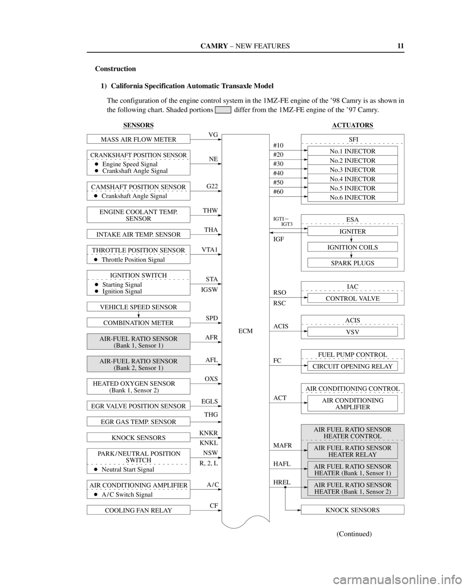
Construction
1) California Specification Automatic Transaxle Model
The configuration of the engine control system in the 1MZ-FE engine of the '98 Camry is as shown in
the following chart. Shaded portions
differ from the 1MZ-FE engine of the '97 Camry.