Page 312 of 4770

9=4 ±01
ELECTRIC COOLING FAN COMPONENTS
INSPECTION
1. INSPECT ENGINE COOLANT TEMPERATURE
SWITCH
(a) Using an ohmmeter, check that there is no continuity
between the terminals when the engine coolant tem±
perature is above 93�C (199�F).
(b) Using an ohmmeter, check that there is continuity
between the terminals when the engine coolant tem±
perature is below 83�C (181 �F).
If continuity is not as specified, replace the switch. 2. DISCONNECT ENGINE COOLANT TEMPERATURE
SWITCH CONNECTOR
Check that the cooling fan rotates.
If not, check the cooling fan relay, cooling fan, engine
main relay and fuse, and check for a short circuit
between the cooling fan relay and engine coolant
temperature switch.
3. CONNECT ENGINE COOLANT TEMPERATURE
SWITCH CONNECTOR
ON±VEHICLE INSPECTION
Low Temperature (Below 83
�C (181�F))
1. TURN IGNITION SWITCH ªONº
Check that the cooling fan stops.
If not, check the cooling fan relay and engine coolant
temperature switch, and check for a separated con±
nector or severed wire between the cooling fan relay
and engine coolant temperature switch.
High Temperature (Above 93�C (199�F))
4. START ENGINE
(a) Raise engine coolant temperature to above 93�C
(199�F).
(b) Check that the cooling fan rotates.
If not, replace the engine coolant temperature switch.
± 5S±FE ENGINECOOLING SYSTEMEG1±262
Page 315 of 4770
ELECTRIC COOLING FAN REMOVAL
(See Components for Removal and Installation)
1. DISCONNECT NEGATIVE (±) TERMINAL CABLE
FROM BATTERY
CAUTION: Work must be started after 90 seconds from
the time the ignition switch is turned to the 'LOCK'
position and the negative (±) terminal cable is discon±
nected from the battery.
5. REMOVE ELECTRIC COOLING FAN
(a) Disconnect the engine coolant temperature switch
connector from the radiator.
(b) Disconnect the engine coolant temperature switch
and electric cooling fan connectors from the fan
shroud.
(c) Remove the 4 bolts and cooling fan. 2. DRAIN ENGINE COOLANT (See page EG1±241)
3. w/ CRUISE CONTROL SYSTEM:
REMOVE CRUISE CONTROL ACTUATOR COVER
4. DISCONNECT UPPER RADIATOR HOSE FROM
RADIATOR
COMPONENTS FOR DISASSEMBLY AND
ASSEMBLY
± 5S±FE ENGINECOOLING SYSTEMEG1±265
Page 316 of 4770
ELECTRIC COOLING FAN INSTALLATION
(See Components for Removal and Installation)
1. INSTALL ELECTRIC COOLING FAN
(a) Install the cooling fan with the 4 bolts.
(b) Connect the engine coolant temperature switch and
electric cooling fan connectors to the fan shroud.
(c) Connect the engine coolant temperature switch connector
to the radiator.
2. CONNECT UPPER RADIATOR HOSE TO RADIATOR
3. w/ CRUISE CONTROL SYSTEM:
INSTALL CRUISE CONTROL ACTUATOR COVER
4. FILL WITH ENGINE COOLANT
(See page EG1±241)
5. CONNECT NEGATIVE (±) TERMINAL CABLE TO
BATTERY
6. START ENGINE AND CHECK FOR LEAKS
ELECTRIC COOLING FAN DISASSEMBLY
(See Components for Disassembly and Assembly)
1. REMOVE FAN
Remove the nut and fan.
ELECTRIC COOLING FAN ASSEMBLY
(See Components for Disassembly and Assembly)
1. INSTALL FAN MOTOR
2. INSTALL FAN 2. REMOVE FAN MOTOR
Remove the screws and fan motor.
± 5S±FE ENGINECOOLING SYSTEMEG1±266
Page 336 of 4770
OIL COOLER REMOVAL
1. DRAIN ENGINE COOLANT
2. REMOVE OIL FILTER
Using SST, remove the oil filter.
SST 09228±06500
3. DISCONNECT WATER BYPASS HOSES FROM OIL
COOLER
Disconnect the 2 water bypass hoses.
OIL COOLER
COMPONENTS FOR REMOVAL AND
INSTALLATION
± 5S±FE ENGINELUBRICATION SYSTEMEG1±286
Page 338 of 4770
(c) Tighten the oil filter by hand until the rubber gasket
contacts the seat of the filler mounting. Then using
SST, give it an additional 3/4 turn to seat the oil filter.
SST 09228±06500
4. FILL WITH ENGINE COOLANT
(See page EG1±241)
5. START ENGINE AND CHECK FOR LEAKS
6. CHECK ENGINE OIL LEVEL 3. INSTALL OIL FILTER
(a) Clean the oil filter contact surface on the filter
mounting. 2. CONNECT WATER BYPASS HOSES
Connect the 2 water bypass hoses.
(b) Lubricate the filter rubber gasket with engine oil.
± 5S±FE ENGINELUBRICATION SYSTEMEG1±288
Page 352 of 4770

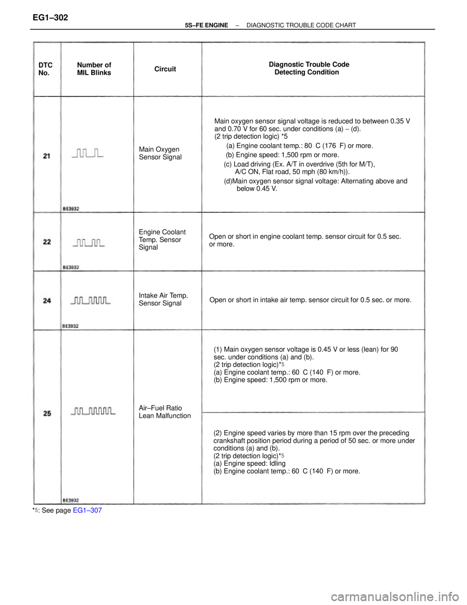
Main oxygen sensor signal voltage is reduced to between 0.35 V
and 0.70 V for 60 sec. under conditions (a) ~ (d).
(2 trip detection logic) *5
(a) Engine coolant temp.: 80�C (176�F) or more.
(b) Engine speed: 1,500 rpm or more.
(c) Load driving (Ex. A/T in overdrive (5th for M/T),
A/C ON, Flat road, 50 mph (80 km/h)).
(d)Main oxygen sensor signal voltage: Alternating above and
below 0.45 V.
(2) Engine speed varies by more than 15 rpm over the preceding
crankshaft position period during a period of 50 sec. or more under
conditions (a) and (b).
(2 trip detection logic)*�
(a) Engine speed: Idling
(b) Engine coolant temp.: 60�C (140�F) or more. (1) Main oxygen sensor voltage is 0.45 V or less (lean) for 90
sec. under conditions (a) and (b).
(2 trip detection logic)*�
(a) Engine coolant temp.: 60�C (140�F) or more.
(b) Engine speed: 1,500 rpm or more. Open or short in engine coolant temp. sensor circuit for 0.5 sec.
or more.
Open or short in intake air temp. sensor circuit for 0.5 sec. or more.Diagnostic Trouble Code
Detecting Condition
Engine Coolant
Temp. Sensor
Signal
Air±Fuel Ratio
Lean Malfunction Intake Air Temp.
Sensor SignalMain Oxygen
Sensor Signal
*�: See page EG1±307Number of
MIL Blinks DTC
No.Circuit
± 5S±FE ENGINEDIAGNOSTIC TROUBLE CODE CHARTEG1±302
Page 353 of 4770
wOpen or short in injector circuit
wFuel line pressure (injector leak, blockage)
wMechanical system malfunction (skipping teeth of timing
belt)
wIgnition system
w Compression pressure (foreign object caught in valve)
wAir leakage
wECM wOpen or short in main oxygen sensor circuit
wMain oxygen sensor
wignition system
wECM wOpen or short in engine coolant temp. sensor circuit
wEngine coolant temp. sensor
wECM
wOpen or short in intake air temp. sensor circuit
wIntake air temp. sensor
wECM wMain oxygen sensor circuit
w Main oxygen sensorMalfunction
Indicator
Lamp*�
*�,*�: See page EG1±306Normal
Mode Trouble AreaMemory`
Test
ModeSee page
EG1±360
EG1±363EG1±352
EG1±356
± 5S±FE ENGINEDIAGNOSTIC TROUBLE CODE CHARTEG1±303
Page 354 of 4770

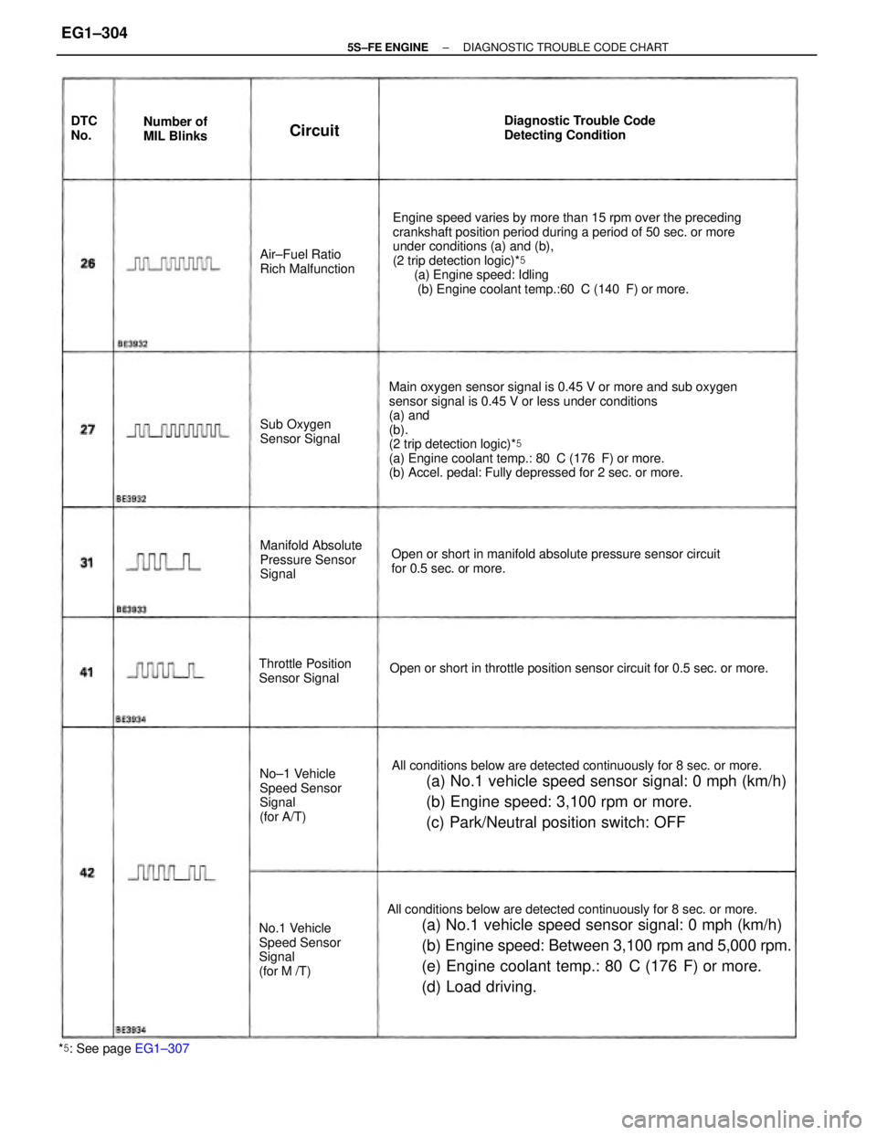
All conditions below are detected continuously for 8 sec. or more.
(a) No.1 vehicle speed sensor signal: 0 mph (km/h)
(b) Engine speed: Between 3,100 rpm and 5,000 rpm.
(e) Engine coolant temp.: 80
�C (176�F) or more.
(d) Load driving.
Engine speed varies by more than 15 rpm over the preceding
crankshaft position period during a period of 50 sec. or more
under conditions (a) and (b),
(2 trip detection logic)*�
(a) Engine speed: Idling
(b) Engine coolant temp.:60�C (140�F) or more.
Main oxygen sensor signal is 0.45 V or more and sub oxygen
sensor signal is 0.45 V or less under conditions
(a) and
(b).
(2 trip detection logic)*�
(a) Engine coolant temp.: 80�C (176�F) or more.
(b) Accel. pedal: Fully depressed for 2 sec. or more.
All conditions below are detected continuously for 8 sec. or more.
(a) No.1 vehicle speed sensor signal: 0 mph (km/h)
(b) Engine speed: 3,100 rpm or more.
(c) Park/Neutral position switch: OFF
Open or short in manifold absolute pressure sensor circuit
for 0.5 sec. or more.
Open or short in throttle position sensor circuit for 0.5 sec. or more.Diagnostic Trouble Code
Detecting Condition
No.1 Vehicle
Speed Sensor
Signal
(for M /T)Manifold Absolute
Pressure Sensor
Signal
No±1 Vehicle
Speed Sensor
Signal
(for A/T) Throttle Position
Sensor SignalAir±Fuel Ratio
Rich Malfunction
Sub Oxygen
Sensor Signal
*�: See page EG1±307Number of
MIL Blinks DTC
No.
Circuit
± 5S±FE ENGINEDIAGNOSTIC TROUBLE CODE CHARTEG1±304