Page 269 of 4770
3. INSPECT ECT SENSOR RESISTANCE
Using an ohmmeter, measure the resistance between
the terminals.
Resistance:
Refer to the graph above
If the resistance is not as specified, replace the
sensor.
4. REINSTALL ECT SENSOR
5. FILL WITH ENGINE COOLANT
ENGINE COOLANT TEMPERATURE
(ECT) SENSOR
ECT SENSOR INSPECTION
1. DRAIN ENGINE COOLANT
2. REMOVE ECT SENSOR
± 5S±FE ENGINEMFI/SFI SYSTEMEG1±219
Page 282 of 4770
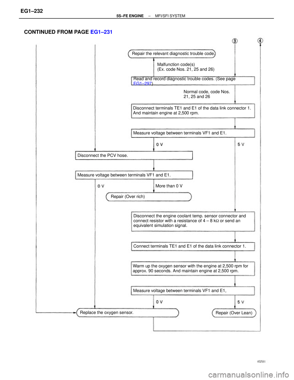
Disconnect the engine coolant temp. sensor connector and
connect resistor with a resistance of 4 ± 8 k
� or send an
equivalent simulation signal.
Warm up the oxygen sensor with the engine at 2,500 rpm for
approx. 90 seconds. And maintain engine at 2,500 rpm.Disconnect terminals TE1 and E1 of the data link connector 1.
And maintain engine at 2,500 rpm.
CONTINUED FROM PAGE EG1±231
Read and record diagnostic trouble codes. (See page
EG1±297)
Connect terminals TE1 and E1 of the data link connector 1.Malfunction code(s)
(Ex. code Nos. 21, 25 and 26)
Measure voltage between terminals VF1 and E1.
Measure voltage between terminals VF1 and E1, Measure voltage between terminals VF1 and E1.Repair the relevant diagnostic trouble code.
Normal code, code Nos.
21, 25 and 26
Replace the oxygen sensor. Disconnect the PCV hose.
Repair (Over Lean) Repair (Over rich)More than 0 V
± 5S±FE ENGINEMFI/SFI SYSTEMEG1±232
Page 288 of 4770
The cooling system is composed of the water jacket (inside the cylinder block and cylinder head),
radiator, water pump, thermostat, electric fan, hoses and other components.
Engine coolant which is heated in the water jacket is pumped to the radiator, through which an
electric fan blows air to cool the coolant as it passes through. Engine coolant which has been
cooled is then sent back to the engine by the water pump, where it cools the engine.
The water jacket is a network of channels in the shell of the cylinder block and cylinder head
through which coolant passes. It is designed to provide adequate cooling of the cylinders and
combustion chambers which become heated during engine operation.
DESCRIPTION
This engine utilizes a pressurized forced circulation cooling system which includes a thermostat
equipped with a bypass valve mounted on the inlet side.
OPERATIONCOOLING SYSTEM
± 5S±FE ENGINECOOLING SYSTEMEG1±238
Page 289 of 4770

RADIATOR
The radiator performs the function of cooling the coolant which has passed through the water
jacket and become hot, and it is mounted in the front of the vehicle. The radiator consists of an
upper tank and lower tank, and a core which connects the two tanks. The upper tank contains the
inlet for coolant from the water jacket and the filler inlet. It also has a hose attached through
which excess coolant or steam can flow. The lower tank has an outlet and drain cock for the
coolant. The core contains many tubes through which coolant flows from the upper tank to the
lower tank as well as to cooling fins which radiate heat away from the coolant in the tubes. The
air sucked through the radiator by the electric fan, as well as the wind generated by the vehicle's
travel, passes through the radiator, cooling the coolant. Models with automatic transmission
include an automatic transmission fluid cooler built into the lower tank of the radiator. A fan with
an electric motor is mounted behind the radiator to assist the flow of air through the radiator. The
fan operates when the engine coolant temperature becomes high in order to prevent it from be-
coming too high.
RADIATOR CAP
The radiator cap is a pressure type cap which seals the radiator, resulting in pressurization of the
radiator as the coolant expands. The pressurization prevents the coolant from boiling even when
the engine coolant temperature exceeds 100°C (212°F). A relief valve (pressurization valve) and a
vacuum valve (negative pressure valve) are built into the radiator cap. The relief valve opens and
lets steam escape through the overflow pipe when the pressure generated inside the cooling sys-
tem exceeds the limit (coolant temperature: 110±120°C (230±248°F), pressure; 58.8103.0 kpa
(0.6±1.05 kgf/cm
2, 8.5±14.9 psi). The vacuum valve opens to alleviate the vacuum which develops
in the cooling system after the engine is stopped and the engine coolant temperature drops. The
valve's opening allows the coolant in the reservoir tank to return to the cooling system.
RESERVOIR TANK
The reservoir tank is used to catch coolant which overflows from the cooling system as a result
of volumetric expansion when the coolant is heated. The coolant in the reservoir tank returns to
the radiator when the coolant temperature drops, thus keeping the radiator full at all times and
avoiding needless coolant loss.
Check the reservoir tank level to learn if the coolant needs to be replenished.
WATER PUMP
The water pump is used for forced circulation of coolant through the cooling system. It is
mounted on the front of the cylinder block and driven by a timing belt.
THERMOSTAT
The thermostat has a wax type bypass valve and is mounted in the water inlet housing. The
thermostat includes a type of automatic valve operated by fluctuations in the engine coolant
temperature. This valve closes when the engine coolant temperature drops, preventing the
circulation of coolant through the engine and thus permitting the engine to warm up rapidly. The
valve opens when the engine coolant temperature has risen, allowing the circulation of coolant.
Wax inside the thermostat expands when heated and contracts when cooled. Heating the wax
thus generates pressure which overpowers the force of the spring which keeps the valve closed,
thus opening the valve. When the wax cools, its contraction allows the force of the spring to take
effect once more, closing the valve. The thermostat in this engine operates at a temperature of
82�C (180�F).
± 5S±FE ENGINECOOLING SYSTEMEG1±239
Page 290 of 4770
PREPARATION
SST (SPECIAL SERVICE TOOLS)
RECOMMENDED TOOLS
09082±00050 TOYOTA Electrical Tester Set09230±01010 Radiator Service Tool Set
6.3 liters (6.7 US qts, 5.5 Imp. qts)Engine coolant temperature switch
Engine coolant temperature switch 09228±06500 Oil Filter Wrench
Engine coolant (w/ Heater)
EQUIPMENT
Radiator cap tester
Ethylene±glycol base
COOLANT
Torque wrenchThermometer
Classification Capacity Heater
Item
± 5S±FE ENGINECOOLING SYSTEMEG1±240
Page 291 of 4770

2. CHECK ENGINE COOLANT QUALITY
There should not be any excessive deposits of rust or
scales around the radiator cap or radiator filler hole,
and the engine coolant should be free from oil.
If excessively dirty, replace the engine coolant.
3. REPLACE ENGINE COOLANT
(a) Remove the radiator cap.
CAUTION: To avoid the danger of being burned, do not
remove It while the engine and radiator are still hot, as
fluid and steam can be blown out under pressure.
(b) Drain the engine coolant from the radiator drain cock
and engine drain plug. (Engine drain plug at the right
rear of cylinder block.)
(c) Close the drain cock and plug.
Torque (Engine drain plug):
13 N±m (130 kgf±cm, 9 ft±lbf)
(d) Slowly fill the system with coolant.
Use a good brand of ethylene±glycol base
coolant and mix it according to the
manufacturer 's directions.
Using engine coolant which includes more than
5096 ethylene±glycol (but not more than 7096) is
recommended.
NOTICE:
wDo not use a alcohol type coolant.
wThe engine coolant should be mixed with demineral±
ized water or distilled water.
Capacity (w/ Heater):
8.3 liters (6.7 US qts, 5.5 Imp.qts)
(a) Reinstall the radiator cap.
(f) Warm up the engine and check for leaks.
(g) Recheck the engine coolant level and refill as neces±
sary.
COOLANT CHECK AND
REPLACEMENT
1. CHECK ENGINE COOLANT LEVEL AT RESERVOIR
TANK
The engine coolant level should be between the
ºLOWº and ªFULLº lines.
If low, check for leaks and add engine coolant up to
the ªFULLº line.
± 5S±FE ENGINECOOLING SYSTEMEG1±241
Page 292 of 4770
WATER PUMP REMOVAL
1. DISCONNECT NEGATIVE (±) TERMINAL CABLE
FROM BATTERY
CAUTION: Work must be started after 90 seconds
from the time the Ignition switch is turned to the
ªLOCKº position and the negative (±) terminal cable
is disconnected from the battery.
2. DRAIN ENGINE COOLANT (See page EG1±241)
3. REMOVE TIMING BELT (See page EG1±26)
4. REMOVE NO. 1 IDLER PULLEY AND TENSION
SPRING
Remove the bolt, pulley and tension spring.
WATER PUMP
COMPONENTS FOR REMOVAL AND
INSTALLATION
± 5S±FE ENGINECOOLING SYSTEMEG1±242
Page 296 of 4770
7. TEMPORARILY INSTALL NO.1 IDLER PULLEY AND
TENSION SPRING
(a) Install the pulley with the bolt. Do not tighten the bolt
yet.
HINT: Use bolt 42 mm (1.65 in.) in length.
(b) Install the tension spring.
(c) Pry the pulley toward the left as far as it will go and
tighten the bolt.
(d) Check that the idler pulley moves smoothly.
8. INSTALL TIMING BELT (See page EG1±33)
9. CONNECT NEGATIVE (±) TERMINAL CABLE TO
BATTERY
10. FILL WITH ENGINE COOLANT
(See page EG1±241) 6. INSTALL NO.2 IDLER PULLEY
(a) Install the pulley with the bolt.
Torque: 42 N±m (425 kgf±cm, 31 ft±lbf)
HINT: Use a bolt 35 mm (1.38 in.) in length.
(b) Check that the idler pulley moves smoothly. 4. INSTALL GENERATOR BELT ADJUSTING BAR
Temporarily install the adjusting bar with the bolt.
5. CONNECT LOWER RADIATOR HOSE TO WATER
INLET (f) Install the 2 nuts holding the water pump cover to the
water bypass pipe.
Torque: 8.8 N±m (90 kgf±cm, 78 in.±Ibf)
± 5S±FE ENGINECOOLING SYSTEMEG1±246

,
radiator, water pump, thermostat, electric fan, hoses and other components.
Engine coolant which is he")

RECOMMENDED TOOLS
09082±00050 TOYOTA Electrical Tester Set09230±01010 Radiator Service Tool Set
6.3 liters (6.7 US qts, 5.5 Imp. qts)Engine coolant temperatur")
 TERMINAL CABLE
FROM BATTERY
CAUTION: Work must be started after 90 seconds
from the time the Ignition switch is turned to the
ªLOCKº position and the n")
 Install the pulley with the bolt. Do not tighten the bolt
yet.
HINT: Use bolt 42 mm (1.65 in.) in length.
(b) Install the")