Page 4397 of 4770

SA08A±01
R00749
R10288
W03213
± SUSPENSION AND AXLEREAR SHOCK ABSORBER
SA±57
2008 Author�: Date�:
REMOVAL
1. REMOVE REAR SIDE SEATBACK
(See page BO±113 or BO±118)
2. REMOVE REAR WHEEL
Torque: 103 N´m (1,050 kgf´cm, 76 ft´lbf)
3. REMOVE FLEXIBLE HOSE AND ABS SPEED SEN-
SOR WIRE HARNESS (w/ ABS) FROM SHOCK AB-
SORBER
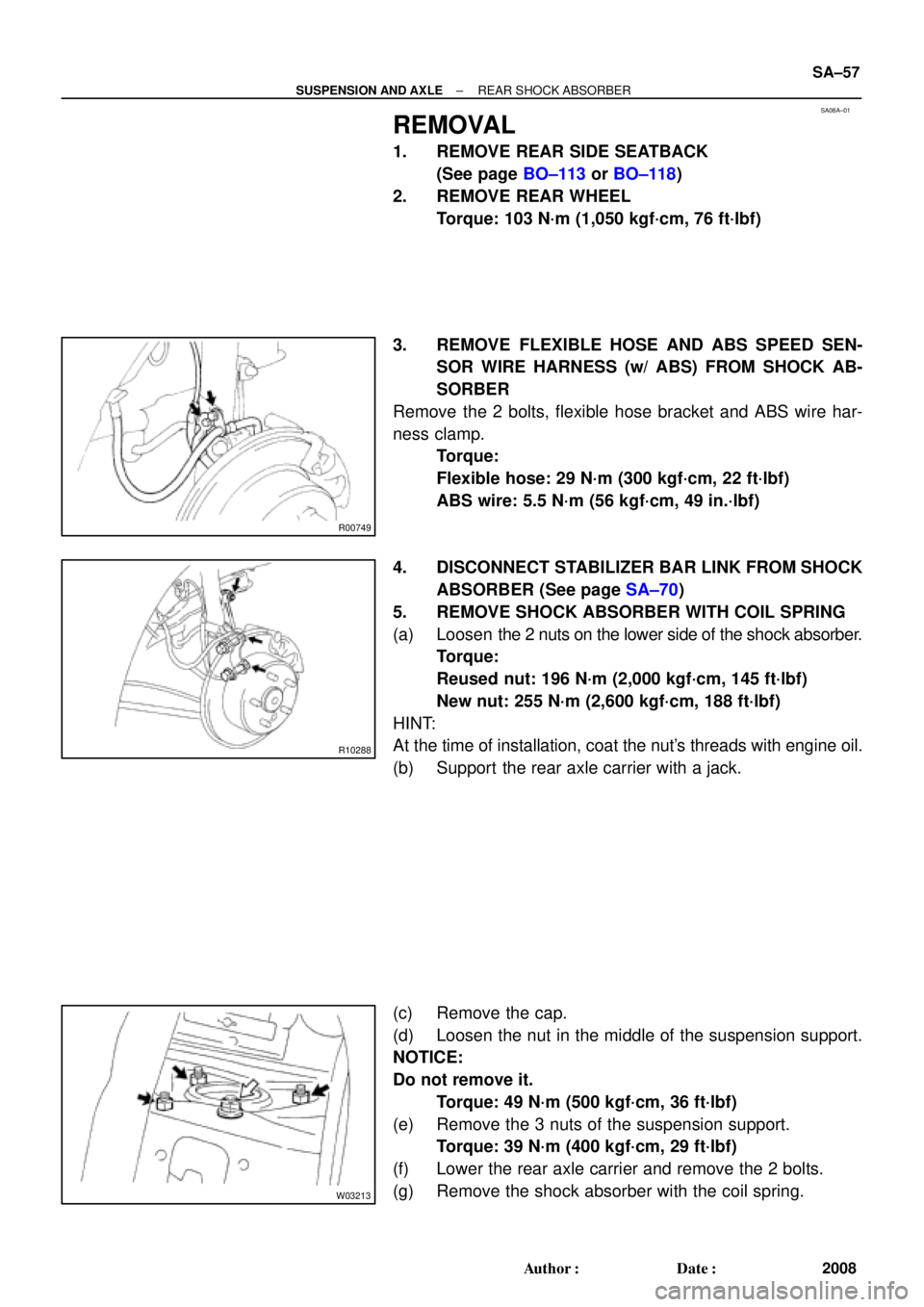
Remove the 2 bolts, flexible hose bracket and ABS wire har-
ness clamp.
Torque:
Flexible hose: 29 N´m (300 kgf´cm, 22 ft´lbf)
ABS wire: 5.5 N´m (56 kgf´cm, 49 in.´lbf)
4. DISCONNECT STABILIZER BAR LINK FROM SHOCK
ABSORBER (See page SA±70)
5. REMOVE SHOCK ABSORBER WITH COIL SPRING
(a) Loosen the 2 nuts on the lower side of the shock absorber.
Torque:
Reused nut: 196 N´m (2,000 kgf´cm, 145 ft´lbf)
New nut: 255 N´m (2,600 kgf´cm, 188 ft´lbf)
HINT:
At the time of installation, coat the nut's threads with engine oil.
(b) Support the rear axle carrier with a jack.
(c) Remove the cap.
(d) Loosen the nut in the middle of the suspension support.
NOTICE:
Do not remove it.
Torque: 49 N´m (500 kgf´cm, 36 ft´lbf)
(e) Remove the 3 nuts of the suspension support.
Torque: 39 N´m (400 kgf´cm, 29 ft´lbf)
(f) Lower the rear axle carrier and remove the 2 bolts.
(g) Remove the shock absorber with the coil spring.
Page 4415 of 4770

Toyota Supports ASE CertificationPage 1 of 1
AC002±00
Title:
A/C COMPRESSOR MAINTENANCE FOR
STORED VEHICLES
Models:
All Models
Technical Service
BULLETIN
July 21, 2000
When a vehicle is stored for a long period (more than one month), the volume of oil
in the A/C compressor may decrease due to oil flow into the condenser, pipes, etc.
If the A/C system is turned on at high engine RPM after a long storage period, A/C
compressor damage may result.
To minimize the possibility of damage to the A/C compressor while storing a vehicle,
perform the following recommended maintenance procedure at
least once a month to
lubricate the compressor.
Recommended
Maintenance Procedure For A/C Compressor Lubrication:
1. Turn
off A/C and blower switches prior to starting engine.
2. Start and warm±up engine until engine speed drops below 1,000 RPM.
3. Turn on the A/C system (including the rear A/C) using the following settings:
�A/C switch: On
�Blower Speed: High
�Engine Speed: Below 1,000 RPM
4. Keep A/C on with engine idling for at least 30 seconds.
5. Turn off A/C system and stop engine.
OP CODEDESCRIPTIONTIMEOPNT1T2
N/ANot Applicable to Warranty ±±±±
HEATING & AIR CONDITIONING
Introduction
Maintenance
Procedure
Warranty
Information
Page 4555 of 4770

Toyota Supports ASE CertificationPage 1 of 1
EG003-03Title:
SULFUR ODOR FROM EXHAUST
Models:
All Models
Technical Service
BULLETIN
February 24, 2003
Some owners of Toyota vehicles may experience a sulfur±like or ªrotten eggº odor from
the exhaust system. Sulfur is a natural component of crude oil from which gasoline is
refined and the amount of sulfur can be decreased through the refining process. The
amount of sulfur in fuel sold in California is regulated, however gasoline sold in other
states can have substantially higher sulfur content. Sulfur content also varies
considerably between gasoline brands and locations.
�All Models.
A sulfur odor emitted from the vehicle's tailpipe does not necessarily indicate that there is
an issue with the engine's running condition, but is most likely directly related to the fuel.
If the vehicle is exhibiting an excessive sulfur odor, the following checks should be
performed:
�If the MIL light is ON, check for DTCs and repair as necessary.
If no trouble is found after performing the above check, recommend the customer try a
different source of fuel.
Replacement of oxygen sensors, air/fuel ratio sensors or catalytic converters will not
reduce the odor and will therefore not
be considered warrantable.
OP CODEDESCRIPTIONTIMEOFPT1T2
N/ANot Applicable to Warranty±±±±
ENGINE
Introduction
Applicable
Vehicles
Repair
Procedure
Warranty
Information
Page 4574 of 4770

Toyota Supports ASE CertificationPage 1 of 1
EG007-02Title:
GENERAL MAINTENANCE TIP
Models:
All '93 ± '03 Models
Technical Service
BULLETIN
March 22, 2002
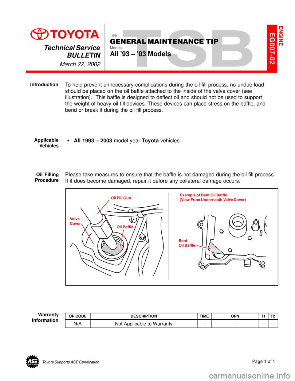
To help prevent unnecessary complications during the oil fill process, no undue load
should be placed on the oil baffle attached to the inside of the valve cover (see
illustration). This baffle is designed to deflect oil and should not be used to support
the weight of heavy oil fill devices. These devices can place stress on the baffle, and
bend or break it during the oil fill process.
�All 1993 ± 2003 model year Toyota vehicles.
Please take measures to ensure that the baffle is not damaged during the oil fill process.
If it does become damaged, repair it before any collateral damage occurs.
Oil Fill Gun
Oil BaffleExample of Bent Oil Baffle
(View From Underneath Valve Cover)
Bent
Oil Baffle
Valve
Cover
OP CODEDESCRIPTIONTIMEOPNT1T2
N/ANot Applicable to Warranty±±±±
ENGINE
Introduction
Applicable
Vehicles
Oil Filling
Procedure
Warranty
Information
Page 4645 of 4770

WARRANTY PARTS MARKING PROCEDURE ± PG006-03September 26, 2003
Page 2 of 3
Dealers are requested to mark the location of the failure of all warranty parts that are
listed below.
This list is not inclusive. There may be other components that can be
marked in the area of failure. All other parts that can be marked should be marked.
assist grip assy headlamps
audio (blemish) headliner
back door garnish hoses
bumper covers instrument panel safety pad sub±assy
cargo cover (retractable) Interior light assemblies and covers
carpet knobs, levers, handles
clutch disc l/pulley pump assy
clutch flywheel mirrors (side and rearview)
combination meter glass navigation or VES screens
console and components pillar garnish
cowl assy rack and pinion/power steering gear assy
cowl side trim sub±assy radiator
cupholders room partition board
cylinder head cover sub±assy rotors (mark where min. runout is exceeded or warped)
dash panel insulator assy seat covers/cushions
dashboard and trim seat tracks
disc wheel soft trim
display panels spare tire cover
door handle assy steering column cover
door moulding steering wheel
door trim panel & molding tail lamps and covers
emblems transmission oil pan
engine oil pan visor
exhaust manifold washer jar
floor and cargo mats wheel cap
gear shift knob wheels
grills
Parts
Marking
Requirement
Parts
Marking
List
Page 4646 of 4770
WARRANTY PARTS MARKING PROCEDURE ± PG006-03September 26, 2003
Page 3 of 3
NOTE:
The following parts do not have to be marked unless the technician can determine
failure and location.
air induction/ejection systems fuel injection systems
all computers fuel injectors
alternators fuel pump
audio (internal) ignition system
batteries internal engine components
bearings internal transmission components
belts oil cooler
catalytic converter power door lock switches
crankshaft remanufactured parts
cruise control starters
distributors suspension components
EGR systems valve covers
engine control systems window regulators
exchange parts wiper motors
exhaust systems
Parts
Marking
List
(Continued)
Page 4706 of 4770
TRANSMISSION OIL COOLER INSTALLATION ± TC003±97 October 17, 1997
Procedure1. Parts removal in preparation for cooler
installation:
A. Remove the 9 bolts, 2 screws and
the center engine under cover.
B. Remove the engine coolant
temperature switch connector and
the wire clamp.
C. Remove battery and tray.
D. Disconnect the cooling fan
connector.
E. Disconnect the No.1 engine coolant
temperature switch wire connector.
F. Remove the 2 bolts and then the
cooling fan.
Page 2 of 6
Fig. 2Center Engine Under Cover
Fig. 3ClampSwitch
Fig. 4
Page 4710 of 4770

TRANSMISSION OIL COOLER INSTALLATION ± TC003±97 October 17, 1997
Procedure3. Final Assembly:
(Continued)
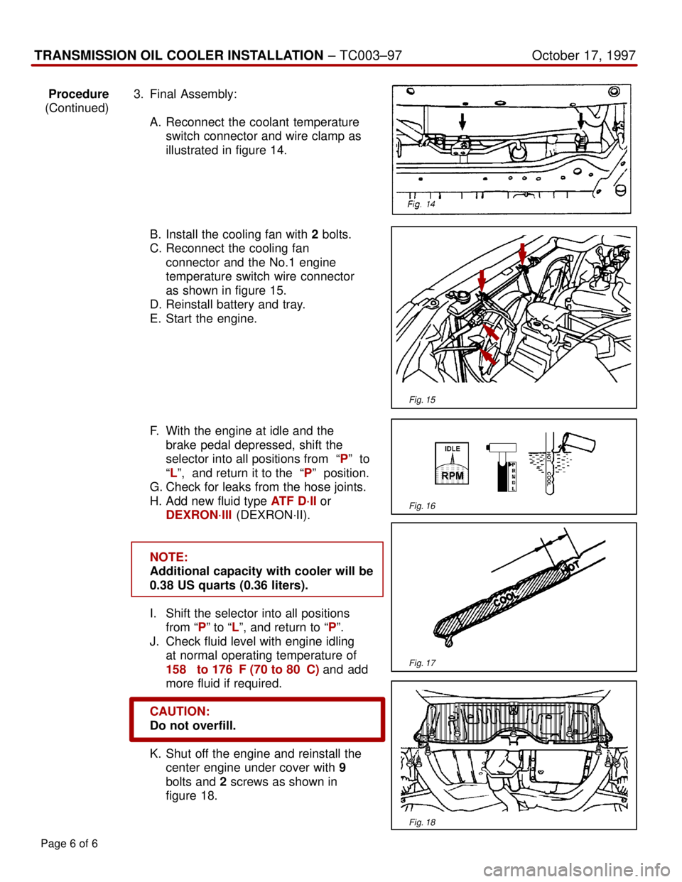
A. Reconnect the coolant temperature
switch connector and wire clamp as
illustrated in figure 14.
B. Install the cooling fan with 2 bolts.
C. Reconnect the cooling fan
connector and the No.1 engine
temperature switch wire connector
as shown in figure 15.
D. Reinstall battery and tray.
E. Start the engine.
F. With the engine at idle and the
brake pedal depressed, shift the
selector into all positions from ªPº to
ªLº, and return it to the ªPº position.
G. Check for leaks from the hose joints.
H. Add new fluid type ATF D´II or
DEXRON´III (DEXRON´II).
NOTE:
Additional capacity with cooler will be
0.38 US quarts (0.36 liters).
I. Shift the selector into all positions
from ªPº to ªLº, and return to ªPº.
J. Check fluid level with engine idling
at normal operating temperature of
158� to 176�F (70 to 80�C) and add
more fluid if required.
CAUTION:
Do not overfill.
K. Shut off the engine and reinstall the
center engine under cover with 9
bolts and 2 screws as shown in
figure 18.
Page 6 of 6
Fig. 15
Fig. 16
Fig. 17
Fig. 18