Page 4310 of 4770
W03349
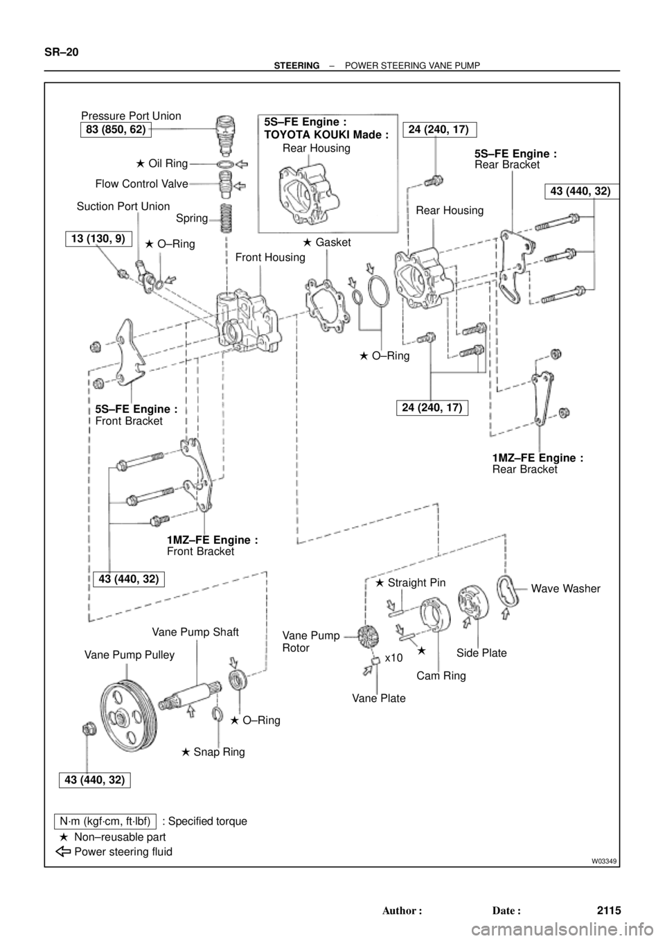
Pressure Port Union
� Oil Ring
Flow Control Valve
Suction Port Union
Spring
� O±Ring
Front Housing� Gasket Rear Housing
Rear Bracket
Rear Housing
� O±Ring
Rear Bracket
Wave Washer
�
Cam Ring � Straight Pin
Vane Plate Rotor
Side Plate Vane Pump
x10
� O±Ring
� Snap Ring
N´m (kgf´cm, ft´lbf)
Non±reusable part
Power steering fluid: Specified torque Vane Pump Shaft
Vane Pump PulleyFront Bracket Front Bracket
�
5S±FE Engine :
TOYOTA KOUKI Made :24 (240, 17)
43 (440, 32)
24 (240, 17)
83 (850, 62)
13 (130, 9)
5S±FE Engine :5S±FE Engine :
1MZ±FE Engine :1MZ±FE Engine :
43 (440, 32)
43 (440, 32) SR±20
± STEERINGPOWER STEERING VANE PUMP
2115 Author�: Date�:
Page 4311 of 4770

SR06O±01
W04220
5S±FE Engine :
1MZ±FE Engine :
Pressure
Feed TubeSST SST
W03360
Example 5S±FE Engine :
A
B
± STEERINGPOWER STEERING VANE PUMP
SR±21
2116 Author�: Date�:
REMOVAL
1. REMOVE FRONT FENDER APRON SEAL RH
Remove the 2 bolts.
2. DISCONNECT RETURN HOSE
NOTICE:
Take care not to spill fluid on the drive belt.
3. DISCONNECT PRESSURE FEED TUBE
(a) 5S±FE Engine:
Remove the clamp plate set bolt and nut.
(b) 5S±FE Engine:
Remove the 2 clamp plates and 2 holders from the tube.
(c) 5S±FE Engine:
Remove the clamp from the tube.
(d) 1MZ±FE Engine:
Remove the 2 clamp plate set nuts.
(e) 1MZ±FE Engine:
Remove the bolt.
(f) 1MZ±FE Engine:
Remove the 2 clamp plates and 2 holders from the tube.
(g) 5S±FE and 1MZ±FE Engines:
Using SST, disconnect the tube.
SST 09631±22020
4. REMOVE DRIVE BELT
Loosen the 2 (A and B) bolts.
5. REMOVE PS VANE PUMP ASSEMBLY WITH PRES-
SURE FEED TUBE
(a) Disconnect the connector from the oil pressure switch.
(b) Loosen bolt A sufficiently so that pump assembly can be
removed.
HINT:
Bolt A cannot be removed.
6. REMOVE PRESSURE FEED TUBE
(a) Remove the oil pressure switch from the union bolt.
NOTICE:
Be careful not to drop the switch.
If the switch is dropped or strongly damaged, replace it with a
new one.
(b) Remove the union bolt and gasket.
Page 4313 of 4770

SR06Q±01
R15196
Caliper Gauge
Micrometer
Vane Pump Shaft
Bushing
Front Housing
N00372
Thickness
Height
Length
R10282
Feeler Gauge
± STEERINGPOWER STEERING VANE PUMP
SR±23
2118 Author�: Date�:
INSPECTION
NOTICE:
When using a vise, do not overtighten it.
1. CHECK OIL CLEARANCE BETWEEN VANE PUMP
SHAFT AND BUSHING
Using a micrometer and caliper gauge, measure the oil clear-
ance.
5S±FE and 1MZ±FE Engines:
Standard clearance:
0.03 ± 0.05 mm (0.0012 ± 0.0020 in.)
Maximum clearance: 0.07 mm (0.0028 in.)
If it is more than the maximum, replace the front housing and
vane pump shaft.
2. INSPECT VANE PUMP ROTOR AND VANE PLATES
(a) Using a micrometer, measure the height, thickness and
length of the plates.
5S±FE and 1MZ±FE Engines:
Minimum height: 8.6 mm (0.339 in.)
Minimum thickness: 1.397 mm (0.0550 in.)
Minimum length: 14.991 mm (0.5902 In.)
(b) Using a feeler gauge, measure the clearance between
the rotor groove and plate.
5S±FE and 1MZ±FE Engines:
Maximum clearance: 0.035 mm (0.0014 in.)
If it is more than the maximum, replace the plate and/or rotor
with one having the same mark stamped on the cam ring.
Page 4315 of 4770
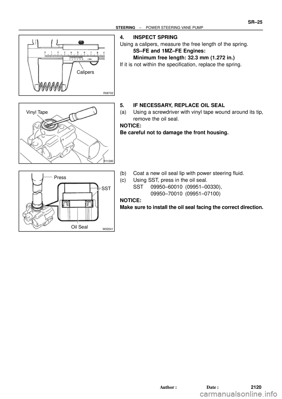
R08702
Calipers
R11290
Vinyl Tape
W03541
Press
SST
Oil Seal
± STEERINGPOWER STEERING VANE PUMP
SR±25
2120 Author�: Date�:
4. INSPECT SPRING
Using a calipers, measure the free length of the spring.
5S±FE and 1MZ±FE Engines:
Minimum free length: 32.3 mm (1.272 in.)
If it is not within the specification, replace the spring.
5. IF NECESSARY, REPLACE OIL SEAL
(a) Using a screwdriver with vinyl tape wound around its tip,
remove the oil seal.
NOTICE:
Be careful not to damage the front housing.
(b) Coat a new oil seal lip with power steering fluid.
(c) Using SST, press in the oil seal.
SST 09950±60010 (09951±00330),
09950±70010 (09951±07100)
NOTICE:
Make sure to install the oil seal facing the correct direction.
Page 4318 of 4770
SR06S±01
W03361
5S±FE Engine :
1MZ±FE Engine :Pressure Feed Tube
Stopper
Pressure
Feed
StopperTube
W03360
Example 5S±FE Engine :
A
B
W03542
5S±FE Engine :
SST
Fulcrum
Length SR±28
± STEERINGPOWER STEERING VANE PUMP
2123 Author�: Date�:
INSTALLATION
1. INSTALL PRESSURE FEED TUBE
(a) Torque the union bolt with a new gasket.
HINT:
Make sure the stopper of the tube is touching the front bracket,
as shown, then torque the union bolt.
5S±FE and 1MZ±FE Engines:
Torque: 52 N´m (525 kgf´cm, 38 ft´lbf)
(b) Install the oil pressure switch to the union bolt.
5S±FE and 1MZ±FE Engines:
Torque: 21 N´m (210 kgf´cm, 15 ft´lbf)
2. INSTALL PS VANE PUMP ASSEMBLY WITH PRESS-
ER FEED TUBE
Temporarily tighten the 2 (A and B) bolts.
3. INSTALL DRIVE BELT
(a) Adjust drive belt tension.
(See page SR±3)
(b) 5S±FE Engine:
Using SST, torque the A bolt.
SST 09249±63010
Torque: 29 N´m (293 kgf´cm, 21 ft´lbf)
HINT:
Use a torque wrench with a fulcrum length of 300 mm (11.81
in.).
Page 4319 of 4770

W03543
1MZ±FE Engine :
Engine Wire Clamp
Fulcrum
Length
SST
W04221
5S±FE Engine :
1MZ±FE Engine :Fulcrum
Length
SST Pressure
Feed Tube
Fulcrum
LengthSST
± STEERINGPOWER STEERING VANE PUMP
SR±29
2124 Author�: Date�:
(c) 1MZ±FE Engine:
Using SST, torque the A bolt.
SST 09249±63010
Torque: 29 N´m (293 kgf´cm, 21 ft´lbf)
HINT:
�Use a torque wrench with a fulcrum length of 300 mm
(11.81 in.).
�Disconnect the clamp with engine wire.
(d) Torque the B bolt.
5S±FE and 1MZ±FE Engines:
Torque: 43 N´m (440 kgf´cm, 32 ft´lbf)
(e) Connect the connector to the oil pressure switch.
NOTICE:
Be careful for oil on the connector.
4. CONNECT PRESSURE FEED TUBE
(a) Using SST, connect the tube.
SST 09631±22020
5S±FE Engine:
Torque: 32 N´m (326 kgf´cm, 24 ft´lbf)
1MZ±FE Engine:
Torque: 20 N´m (203 kgf´cm, 15 ft´lbf)
HINT:
�Use a torque wrench with a fulcrum length of 300 mm
(11.81 in.).
�This torque value is effective in case that SST is parallel
to a torque wrench.
(b) 5S±FE Engine:
Install the clamp to the tube.
(c) 5S±FE Engine:
Install the 2 clamp plates and 2 holders to the tube.
(d) 5S±FE Engine:
Install the clamp plate set bolt.
(e) 5S±FE Engine:
Install the clamp plate set nut.
Torque: 10 N´m (100 kgf´cm, 7 ft´lbf)
(f) 1MZ±FE Engine:
Install the 2 clamp plates and 2 holders to the tube.
(g) 1MZ±FE Engine:
Tighten the bolt.
(h) 1MZ±FE Engine:
Install the 2 clamp plate set nuts.
Torque: 7.8 N´m (80 kgf´cm, 69 in.´lbf)
5. CONNECT RETURN HOSE
Page 4345 of 4770

W03086
F02267
1
2
F01195
Bolt
Adjusting
ValueSet Bolt
15'
30'Adjusting Bolt90105±15001 90105±15004 90105±15005 90105±15006
45'
1°00'
1°15'
1°30'121212121 Dot 2 Dots 3 Dots
± SUSPENSION AND AXLEFRONT WHEEL ALIGNMENT
SA±5
1956 Author�: Date�:
5. ADJUST CAMBER
NOTICE:
After the camber has been adjusted, inspect the toe±in.
(a) Remove the front wheels and speed sensor clamp.
(b) Remove the 2 nuts on the lower side of the shock absorb-
er.
(c) Coat the threads of the nuts with engine oil.
(d) Temporarily install the 2 nuts.
(e) Adjust the camber by pushing or pulling the lower side of
the shock absorber in the direction in which the camber
adjustment is required.
(f) Tighten the nuts.
Torque: 211 N´m (2,150 kgf´cm, 156 ft´lbf)
(g) Install the front wheels.
Torque: 103 N´m (1,050 kgf´cm, 76 ft´lbf)
(h) Check the camber.
HINT:
�Try to adjust the camber to the center value.
�Adjusting value for the set bolts is 6' ± 30' (0.1° ± 0.5°).
If the camber is not within the specification, using the table be-
low, estimate for how much additional camber adjustment will
be required, and select the camber adjusting bolt.
(i) Follow the above mentioned steps again. Between step
(b) and (c), exchange 1 or 2 selected bolts.
HINT:
When exchanging the 2 bolts, exchange 1 bolt for each time.
Page 4374 of 4770

2. REMOVE FLEXIBLE HOSE AN")
SA07N±01
Z19346
To Outside SA±34
± SUSPENSION AND AXLEFRONT SHOCK ABSORBER
1985 Author�: Date�:
REMOVAL
1. REMOVE FRONT WHEEL
Torque: 103 N´m (1,050 kgf´cm, 76 ft´lbf)
2. REMOVE FLEXIBLE HOSE AND ABS SPEED SEN-
SOR WIRE HARNESS (w/ ABS) AND CLAMP FROM
SHOCK ABSORBER
Remove the bolt, flexible hose and ABS wire harness clamp.
Torque: 29 N´m (300 kgf´cm, 22 ft´lbf)
3. DISCONNECT STABILIZER BAR LINK FROM SHOCK
ABSORBER (See page SA±48)
4. DISCONNECT SHOCK ABSORBER FROM STEERING
KNUCKLE
(a) Remove the 2 nuts and bolts on the lower side of the
shock absorber.
Torque: 211 N´m (2,150 kgf´cm, 156 ft´lbf)
(b) Remove the shock absorber from the steering knuckle.
HINT:
At the time of installation, coat the nut's threads with engine oil.
5. REMOVE SHOCK ABSORBER WITH COIL SPRING
Remove the 3 nuts, suspension support No.2 and shock ab-
sorber with the coil spring.
Torque: 80 N´m (820 kgf´cm, 59 ft´lbf)
HINT:
At the time of installation rotate the suspension support and set
it in the direction, as shown in the illustration.