Page 3455 of 4770
S05300
TMC
Made
TMMK
Made
S05282
± ENGINE MECHANICAL (5S±FE)CYLINDER HEAD
EM±63
1235 Author�: Date�:
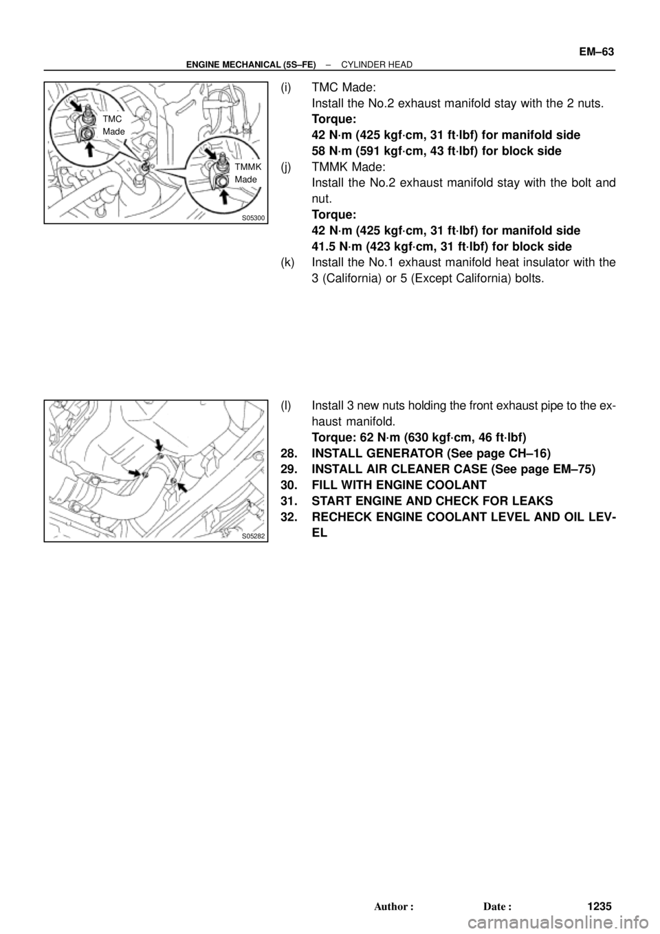
(i) TMC Made:
Install the No.2 exhaust manifold stay with the 2 nuts.
Torque:
42 N´m (425 kgf´cm, 31 ft´lbf) for manifold side
58 N´m (591 kgf´cm, 43 ft´lbf) for block side
(j) TMMK Made:
Install the No.2 exhaust manifold stay with the bolt and
nut.
Torque:
42 N´m (425 kgf´cm, 31 ft´lbf) for manifold side
41.5 N´m (423 kgf´cm, 31 ft´lbf) for block side
(k) Install the No.1 exhaust manifold heat insulator with the
3 (California) or 5 (Except California) bolts.
(l) Install 3 new nuts holding the front exhaust pipe to the ex-
haust manifold.
Torque: 62 N´m (630 kgf´cm, 46 ft´lbf)
28. INSTALL GENERATOR (See page CH±16)
29. INSTALL AIR CLEANER CASE (See page EM±75)
30. FILL WITH ENGINE COOLANT
31. START ENGINE AND CHECK FOR LEAKS
32. RECHECK ENGINE COOLANT LEVEL AND OIL LEV-
EL
Page 3456 of 4770

EM0YV±01
A02195
Radiator Reservoir Hose
Generator Drive BeltUpper Radiator
Hose
Support BracketFront Exhaust Pipe PS Oil Pressure Switch
ConnectorBattery TrayBattery
PS Pump Drive Belt
PS Pump
Support Stay Upper Radiator Support
Lower Radiator Hose
A/C Compressor
Cylinder Block Insulator
LH Front Fender Apron Seal
Oil Cooler Hose (A/T)
Cruise Control ActuatorEVAP Hose
Air Filter Upper Radiator
Support
EVAP Hose Hood
PCV Hose
Support
Bracket � Gasket
�
� Non±reusable part� Gasket
�Clamp
N´m (kgf´cm, ft´lbf)
62 (630, 46)
56 (570, 41)
�
: Specified torque
Washer Hose
for Windshield
No.1 Electric
Cooling Fan
Connector
ECT Switch
Connector No.2 Electric
Cooling Fan
ConnectorRadiator
Assembly
A/C Compressor
ConnectorLower Radiator
Support
RH Front Fender
Aplon Seal
Cruise
Control
Actuator
Connector
Battery
Hold±Down
ClampAir Cleaner
Case
VSV
Connector
for EVAP
EVAP
Hose
IAT Sensor
Connector
Air
Cleaner
Cap
EM±64
± ENGINE MECHANICAL (5S±FE)ENGINE UNIT
1236 Author�: Date�:
ENGINE UNIT
COMPONENTS
Page 3459 of 4770
S05316
M/T
Engine
No.2 Exhaust
Manifold Stay
(TMMK Made)
(TMC Made)
Exhaust Pipe Bracket
Oil Pan
Insulator
No.1 Exhaust
Manifold Stay
Back±Up Light Switch ConnectorNo.2 Rear End Plate Flywheel
LH Stiffener Plate
Clutch Disk
Clutch Cover
Engine Wire
VSS Connector
Wire Clamp
Ground Strap
Transaxle No.1 Rear End PlateIntake Manifold
Stay RH Stiffener Plate
N´m (kgf´cm, ft´lbf)
� Precoated partx 8
88 (900, 65)
19 (195, 14)
64(650, 47)
64(650, 47)
64(650, 47)64(650, 47)
�
: Specified torquex 6
± ENGINE MECHANICAL (5S±FE)ENGINE UNIT
EM±67
1239 Author�: Date�:
Page 3460 of 4770
A02187
A/T
Engine
No.2 Exhaust
Manifold Stay
(TMC Made)
Exhaust Pipe Bracket
Oil Pan
InsulatorLH Stiffener Plate
Engine Wire
VSS Connector
Wire Clamp
Ground Strap No.1 Rear End PlateIntake Manifold
Stay RH Stiffener Plate
N´m (kgf´cm, ft´lbf)
� Precoated partx 8 (TMMK Made)
No.2 Rear End Plate
Transaxle No.1 Exhaust
Manifold Stay
PNP Switch
Connector
StarterThrottle Cable Clamp
Solenoid Connector
Front SpacerDrive Plate
Rear Spacer
Throttle Cable
Solenoid Connector x 6
83 (850, 61)27 (280, 20)
66 (670, 48)
66 (670, 20)
66 (670, 48)
66 (670, 48)
� �
: Specified torque
EM±68
± ENGINE MECHANICAL (5S±FE)ENGINE UNIT
1240 Author�: Date�:
Page 3461 of 4770
ENGINE UNIT
EM±69
1241 Author�: Date�:
REMOVAL
1. REMOVE HOOD
2. REMOVE FRONT FENDER APRON SEALS
3. DRAIN ENGINE COOLANT
4. DRAIN ENGINE OIL
5. DISCONNEC")
EM08F±04
S05251
± ENGINE MECHANICAL (5S±FE)ENGINE UNIT
EM±69
1241 Author�: Date�:
REMOVAL
1. REMOVE HOOD
2. REMOVE FRONT FENDER APRON SEALS
3. DRAIN ENGINE COOLANT
4. DRAIN ENGINE OIL
5. DISCONNECT ACCELERATOR CABLE
6. REMOVE AIR CLEANER CAP
(a) Disconnect the IAT sensor connector.
(b) Disconnect the VSV connector for the EVAP
(c) Disconnect the PCV hose from the cylinder head cover.
(d) Disconnect the EVAP hose from the throttle body.
(e) Disconnect the EVAP hose from the VSV.
(f) Disconnect the 2 clamps, and disconnect the air cleaner
cap from the air cleaner case.
(g) Loosen hose clamp, and disconnect the air cleaner hose
from the throttle body.
(h) Remove the air cleaner cap and hose assembly.
7. REMOVE AIR CLEANER CASE
(a) Remove the air filter.
(b) Remove the 3 bolts and air cleaner case.
8. REMOVE BATTERY AND TRAY
9. REMOVE CRUISE CONTROL ACTUATOR
10. REMOVE RADIATOR (See page CO±18)
11. REMOVE FRONT EXHAUST PIPE
(a) Remove the 2 bolts holding the support stay to the sup-
port bracket.
(b) Remove the 2 bolts holding the support bracket to the
front frame.
(c) Remove the 2 bolts and 2 nuts holding the front exhaust
pipe to the center exhaust pipe.
(d) Remove the 3 nuts holding the front exhaust pipe to the
exhaust manifold.
(e) Remove the front exhaust pipe and 2 gaskets.
(f) Remove the nut and support bracket.
12. DISCONNECT CONNECTORS, WIRES, CABLES,
CLAMPS AND HOSES
(a) Disconnect the generator wire.
(b) Disconnect the generator connector.
(c) Disconnect the wire clamp from the generator.
(d) Disconnect the starter cable.
(e) Disconnect the starter connector.
(f) Disconnect the DLC1 from the bracket.
Page 3463 of 4770
S05250
Connector
S05246
S05254
M/T
S04616
A/T
S05247
± ENGINE MECHANICAL (5S±FE)ENGINE UNIT
EM±71
1243 Author�: Date�:
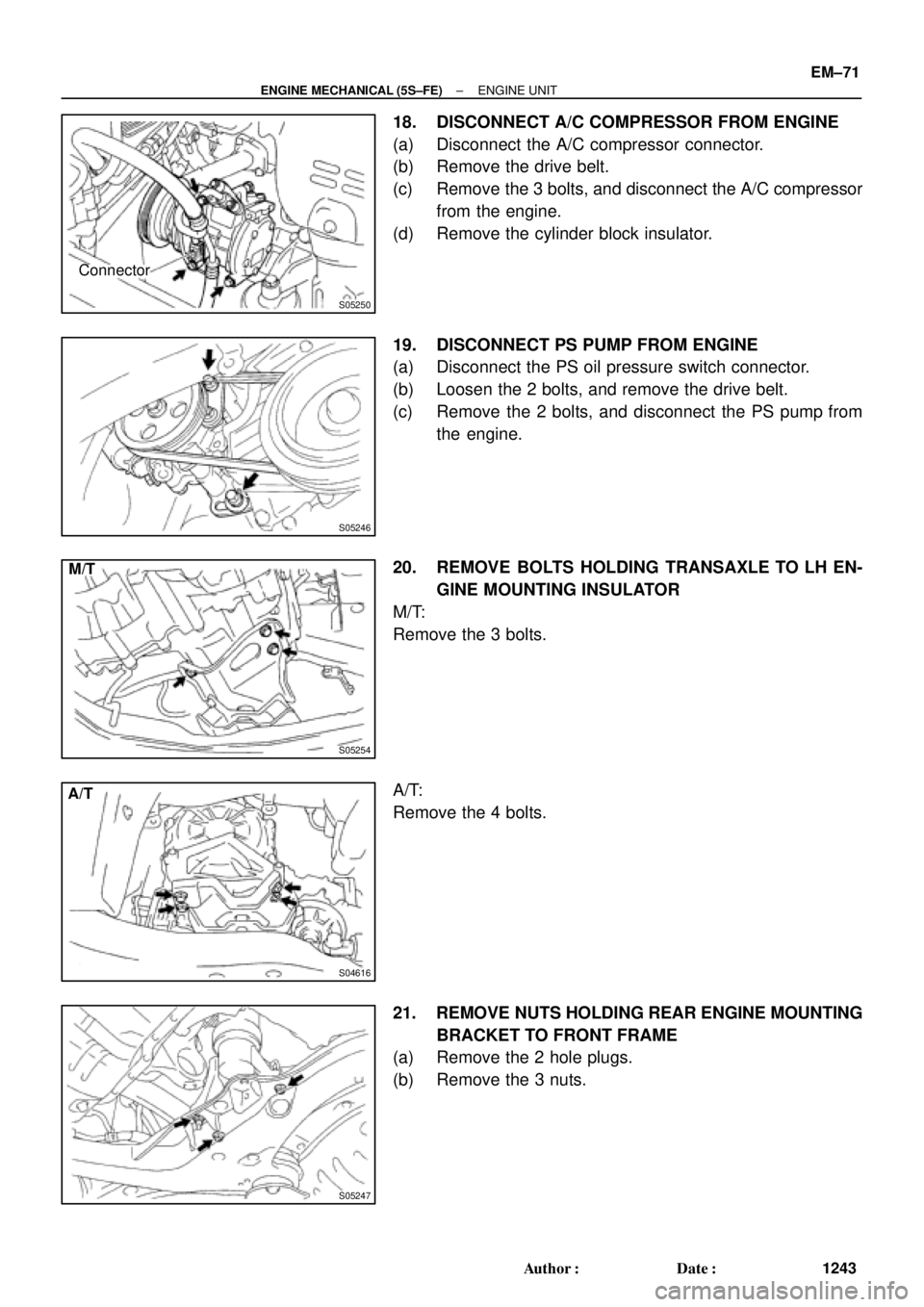
18. DISCONNECT A/C COMPRESSOR FROM ENGINE
(a) Disconnect the A/C compressor connector.
(b) Remove the drive belt.
(c) Remove the 3 bolts, and disconnect the A/C compressor
from the engine.
(d) Remove the cylinder block insulator.
19. DISCONNECT PS PUMP FROM ENGINE
(a) Disconnect the PS oil pressure switch connector.
(b) Loosen the 2 bolts, and remove the drive belt.
(c) Remove the 2 bolts, and disconnect the PS pump from
the engine.
20. REMOVE BOLTS HOLDING TRANSAXLE TO LH EN-
GINE MOUNTING INSULATOR
M/T:
Remove the 3 bolts.
A/T:
Remove the 4 bolts.
21. REMOVE NUTS HOLDING REAR ENGINE MOUNTING
BRACKET TO FRONT FRAME
(a) Remove the 2 hole plugs.
(b) Remove the 3 nuts.
Page 3465 of 4770
ENGINE UNIT
EM±73
1245 Author�: Date�:
30. A/T:
REMOVE STARTER (See page ST±5)
31. DISCONNECT CONNECTORS
(a) Disconne")
S05526
TMMK
Made
TMC
Made
A02198
S05530
S05529
Turn
± ENGINE MECHANICAL (5S±FE)ENGINE UNIT
EM±73
1245 Author�: Date�:
30. A/T:
REMOVE STARTER (See page ST±5)
31. DISCONNECT CONNECTORS
(a) Disconnect the VSS connector.
(b) M/T:
Disconnect the back±up light switch connector.
(c) A/T:
Disconnect the PNP switch connector.
(d) A/T:
Disconnect the 2 solenoid connectors.
32. REMOVE NO.1 EXHAUST MANIFOLD STAY
Remove the 2 bolts and manifold stay.
33. REMOVE NO.2 EXHAUST MANIFOLD STAY AND LH
STIFFENER PLATE
(a) TMC Made:
Remove the 2 nuts and manifold stay.
(b) TMMK Made:
Remove the bolt, nut and manifold stay.
(c) Remove the 2 bolts and stiffener plate.
34. REMOVE INTAKE MANIFOLD STAY
Remove the 2 bolts and intake manifold stay.
35. REMOVE RH STIFFENER PLATE
Remove the 4 bolts and stiffener plate.
36. REMOVE EXHAUST PIPE BRACKET, OIL PAN INSU-
LATOR AND NO.2 REAR END PLATE
(a) Remove the 2 bolts and exhaust pipe bracket.
(b) Remove the 2 bolts, oil pan insulator and rear end plate.
37. A/T:
REMOVE TORQUE CONVERTER CLUTCH BOLTS
(a) Turn the crankshaft pulley bolt to gain access to each bolt.
(b) Hold the crankshaft pulley bolt with a wrench, and remove
the 6 bolts.
Page 3468 of 4770
ENGINE UNIT
1248 Author�: Date�:
7. A/T:
INSTALL TORQUE CONVERTER CLUTCH BOLTS
(a) Apply a")
Z19014Turn
Black
Colored
Bolt A/T
S05530
A02198
S05526
TMC
Made
TMMK
Made
EM±76
± ENGINE MECHANICAL (5S±FE)ENGINE UNIT
1248 Author�: Date�:
7. A/T:
INSTALL TORQUE CONVERTER CLUTCH BOLTS
(a) Apply adhesive to 2 or 3 threads of the bolt end.
Adhesive:
Part No. 08833±00070, THREE BOND 1324 or equiva-
lent
(b) Hold the crankshaft pulley bolt with a wrench, and install
the 6 bolts evenly.
Torque: 27 N´m (280 kgf´cm, 20 ft´lbf)
HINT:
First tighten the black colored bolt, install the other bolts.
8. INSTALL NO.2 REAR END PLATE, OIL PAN INSULA-
TOR AND EXHAUST PIPE BRACKET
(a) Install the oil pan insulator to the rear end plate.
(b) Install the rear end plate and exhaust pipe bracket with
the 4 bolts.
Torque:
9.3 N´m (95 kgf´cm, 82 in.´lbf) for 10 mm head
19 N´m (195 kgf´cm, 14 ft´lbf) for 12 mm head
9. INSTALL RH STIFFENER PLATE
Install the stiffener plate with the 4 bolts.
Torque: 39 N´m (398 kgf´cm, 29 ft´lbf)
10. INSTALL INTAKE MANIFOLD STAY
Install the manifold stay with the 2 bolts.
Torque: 39 N´m (398 kgf´cm, 29 ft´lbf)
11. INSTALL LH STIFFENER PLATE AND NO.2 EXHAUST
MANIFOLD STAY
(a) TMC Made:
Temporarily install the stiffener plate and manifold stay
with the 2 bolts and 2 nuts.
(b) TMMK Made:
Temporarily install the stiffener plate and manifold stay
with the 3 bolts and nut.
(c) Tighten the 2 bolts holding the stiffener plate to the trans-
axle.

(TMC Made)
Exhaust Pipe Bracket
Oil Pan
Insulator
No.1 Exhaust
Manifold Stay
Back±Up Light Switch ConnectorNo.2 Rear End Plate Flywheel
LH Sti")

Exhaust Pipe Bracket
Oil Pan
InsulatorLH Stiffener Plate
Engine Wire
VSS Connector
Wire Clamp
Ground Strap No.1 Rear End PlateIntake Manifold
St")