Page 3347 of 4770

DI1KK±03
± DIAGNOSTICSENGINE IMMOBILISER SYSTEM
DI±927
1162 Author�: Date�:
PROBLEM SYMPTOMS TABLE
SymptomSuspect AreaSee page
Immobiliser is not set.
(Engine starts with key codes other than the registered key code.)2. ECMIN±31
Engine does not start.
1. Key
2. Wire harness
3. Transponder key coil
4. Amplifier
5. ECM*1
IN±31
BE±128
IN±31
Security indicator is always ON.
1. Security indicator
2. Wire harness
3. ECM*2
IN±31
IN±31
Security indicator is always ON.
(Although code has been registered in the automatic registration
mode, indicator is not OFF.)1. Wire harness
2. Transponder key coil
3. Amplifier
4. ECMIN±31
BE±128
IN±31
Security indicator is OFF
(When DTC of immobiliser is output)
1. Wire harness
2. Transponder key coil
3. Amplifier
4. ECMIN±31
BE±128
IN±31
Security indicator is OFF.
(When DTC of immobiliser is not output)1. Wire harness
2. ECMIN±31
IN±31
Security indicator is abnormally brinking.1. Wire harness
2. ECMIN±31
IN±31
*1 : Check that the key which did not start the engine has been registered and that it is possible to start with
other already registered key codes.
*2 : Finish the automatic registration mode because the mode might still remain.
Page 3349 of 4770
I08435
ECM
E10 28
93
E10
E10 3
4G±W
R±L
L±Y Transponder Key Amplifier
CODE
RXCK
TXCT 5S±FE engine:
G±W
R±L
L±Y 1
II4
4
II4
2
II4
± DIAGNOSTICSENGINE IMMOBILISER SYSTEM
DI±929
1164 Author�: Date�:
DTC B2796/99 No Communication in Immobiliser system
CIRCUIT DESCRIPTION
DTC No.DTC Detecting ConditionTrouble Area
B2796/99No communication
�Key
�Transponder Key Coil
�Transponder Key Amplifier
�Wireharness
�ECM
WIRING DIAGRAM
DI4FF±01
Page 3351 of 4770
± DIAGNOSTICSENGINE IMMOBILISER SYSTEM
DI±931
1166 Author�: Date�:
INSPECTION PROCEDURE
1 Check transponder key coil (See page BE±128).
NG Replace transponder key coil.
OK
2 Check harness and connector between transponder key amplifier and ECM.
NG Repair or replace harness and connector.
OK
3 Does it operate normally after replacement of transponder key amplifier?
Yes Replace transponder key amplifier.
No
Replace ECM.
Page 3355 of 4770
I08435
ECM
E10 28
93
E10
E10 3
4G±W
R±L
L±Y Transponder Key Amplifier
CODE
RXCK
TXCT 5S±FE engine:
G±W
R±L
L±Y 1
II4
4
II4
2
II4
± DIAGNOSTICSENGINE IMMOBILISER SYSTEM
DI±935
1170 Author�: Date�:
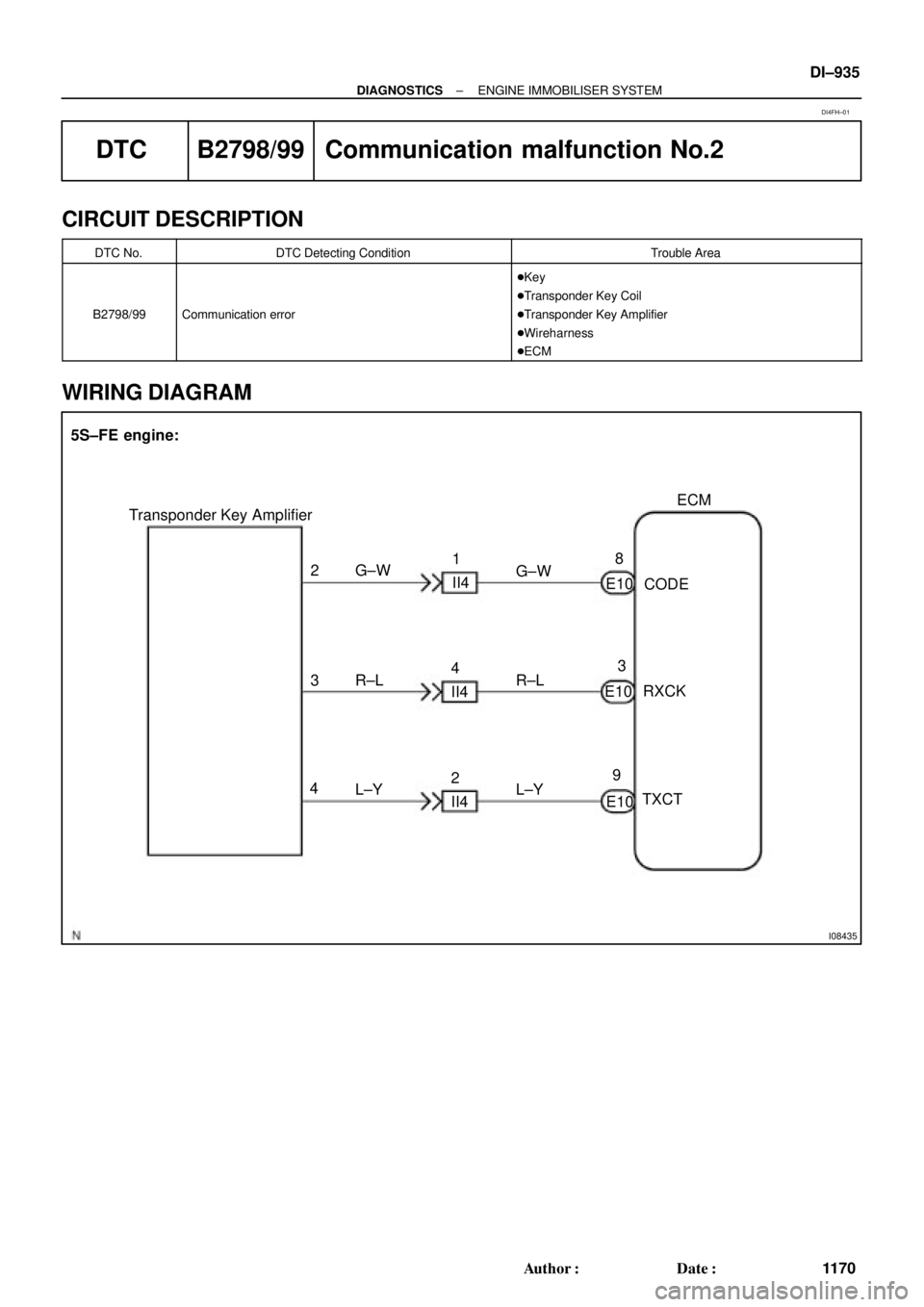
DTC B2798/99 Communication malfunction No.2
CIRCUIT DESCRIPTION
DTC No.DTC Detecting ConditionTrouble Area
B2798/99Communication error
�Key
�Transponder Key Coil
�Transponder Key Amplifier
�Wireharness
�ECM
WIRING DIAGRAM
DI4FH±01
Page 3357 of 4770
± DIAGNOSTICSENGINE IMMOBILISER SYSTEM
DI±937
1172 Author�: Date�:
INSPECTION PROCEDURE
1 Check transponder key coil (See page BE±128).
NG Replace transponder key coil
OK
2 Check harness and connector between transponder key amplifier and ECM.
NG Repair or replace harness and connector
OK
3 Does it operate normally after replacement of transponder key amplifier?
Yes Replace transponder key amplifier.
No
Replace ECM.
Page 3395 of 4770
COMPRESSION
EM±3
1175 Author�: Date�:
COMPRESSION
INSPECTION
HINT:
If there is lack of power, excessive oil consumption or poor fuel
ec")
EM07Y±05
S05312
Compression
Gauge
± ENGINE MECHANICAL (5S±FE)COMPRESSION
EM±3
1175 Author�: Date�:
COMPRESSION
INSPECTION
HINT:
If there is lack of power, excessive oil consumption or poor fuel
economy, measure the compression pressure.
1. WARM UP AND STOP ENGINE
Allow the engine to warm up to normal operating temperature.
2. DISCONNECT IGNITION COIL CONNECTORS
3. REMOVE SPARK PLUGS (See page IG±1)
4. INSPECT CYLINDER COMPRESSION PRESSURE
(a) Insert a compression gauge into the spark plug hole.
(b) Fully open the throttle.
(c) While cranking the engine, measure the compression
pressure.
HINT:
Always use a fully charged battery to obtain engine speed of
250 rpm or more.
(d) Repeat steps (a) through (c) for each cylinder.
NOTICE:
This measurement must be done in as short a time as pos-
sible.
Compression pressure:
1,226 kPa (12.5 kgf/cm
2, 178 psi) or more
Minimum pressure: 981 kPa (10.0 kgf/cm
2, 142 psi)
Difference between each cylinder:
98 kPa (1.0 kgf/cm
2, 14 psi) or less
(e) If the cylinder compression in one or more cylinders is low,
pour a small amount of engine oil into the cylinder through
the spark plug hole and repeat steps (a) through (c) for
cylinders with low compression.
�If adding oil helps the compression, it is likely that
the piston rings and/or cylinder bore are worn or
damaged.
�If pressure stays low, a valve may be sticking or
seating is improper, or there may be leakage past
the gasket.
5. REINSTALL SPARK PLUGS (See page IG±1)
6. RECONNECT IGNITION COIL CONNECTORS
Page 3403 of 4770

EM082±04
Z19417
TDCCrankshaft
Gear
No.1 Balance
Shaft Gear30°
AB
AB 1
2
3
4
100°
210°
280°
P06121
C C
Z19411
No.1 Balance ShaftMark B
Mark A
No.2 Housing
Z19413
No.1 Balance
Shaft
Mark B
Mark A No.2 Housing
± ENGINE MECHANICAL (5S±FE)BALANCE SHAFT BACKLASH
EM±11
1183 Author�: Date�:
BALANCE SHAFT BACKLASH
ON±VEHICLE INSPECTION
1. REMOVE OIL PAN AND OIL STRAINER
(See page LU±7)
2. INSPECT BACKLASH OF CRANKSHAFT GEAR AND
NO.1 BALANCE SHAFT GEAR
NOTICE:
Backlash between the crankshaft gear and No.1 balance
shaft gear varies with the rotation of the balance shaft and
the deviation of the crankshaft gear. Accordingly, it is nec-
essary to measure the backlash at the 4 points shown in
the illustration on the left.
(a) Turn the crankshaft 2 or 3 times to settle the crankshaft
gear and No.1 balance shaft gear.
(b) When No.1 piston is at TDC, check that the punch marks
C shown in the illustration of the balance shafts are
aligned with the grooves of the No.2 housing.
(c) Check that punch marks A and B are at the positions on
the No.1 balance shaft indicated in the illustration.
(d) First turn the crankshaft clockwise, and align the groove
of the No.2 balance shaft housing with punch mark A of
the No.1 balance shaft.
Page 3405 of 4770
BALANCE SHAFT BACKLASH
EM±13
1185 Author�: Date�:
(p) Turn the crankshaft clockw")
Z19415
No.1 Balance
Shaft
Mark B
Mark A
No.2 Housing
Z19408
2
46 153
Z19409
1
35 Pull
264
± ENGINE MECHANICAL (5S±FE)BALANCE SHAFT BACKLASH
EM±13
1185 Author�: Date�:
(p) Turn the crankshaft clockwise again to align the groove
of the No.2 housing with punch mark B.
(q) Set the dial indicator. (See step (e))
(r) Measure the backlash. (See step (f))
Standard backlash (at punch mark B):
0.025 ± 0.085 mm (0.0010 ± 0.0033 in.)
(s) Remove the dial indicator.
If even one of the 4 points measured above exceeds the back-
lash specification, adjust the backlash with new spacers.
NOTICE:
Use the same size spacers for both the left and right sides.
HINT:
�Varying the spacer thickness by 0.02 mm (0.0008 in.)
changes the backlash by about 0.014 mm (0.0006 in.).
�If the backlash is greater than the permitted maximum,
select a thinner shim.
�If the backlash is less than the specification, select a thick-
er shim.
3. REPLACE NEW SPACERS
(a) Uniformly loosen the 6 bolts in the sequence shown.
(b) Replace the spacers with new ones.
4. TIGHTEN BALANCE SHAFT ASSEMBLY
While pulling the center part of the engine balancer in the direc-
tion of the arrow, uniformly tighten the 6 bolts in several passes,
in the sequence shown.
Torque: 49 N´m (500 kgf´cm, 36 ft´lbf)
5. INSPECT AND ADJUST BACKLASH OF CRANK-
SHAFT GEAR AND NO.1 BALANCE SHAFT GEAR
(See step 2)
6. REINSTALL OIL STRAINER AND OIL PAN
(See page LU±13)