Page 2826 of 4770

641 Author�: Date�:
2. Chapter 2: On±Vehicle Repair
(�: A140E AUTOMATIC TRANSAXLE Repair Manual Pub. No. RM385U)
SymptomSuspect AreaSee page
Vehicle")
DI±406
± DIAGNOSTICSAUTOMATIC TRANSAXLE (A140E)
641 Author�: Date�:
2. Chapter 2: On±Vehicle Repair
(�: A140E AUTOMATIC TRANSAXLE Repair Manual Pub. No. RM385U)
SymptomSuspect AreaSee page
Vehicle does not move in any forward positions and reverse posi-
tion
1. Manual valve
2. Throttle valve
3. Primary regulator valve
4. Off±vehicle repair matrix chart�
�
�
±
Vehicle does not move in R position1. Off±vehicle repair matrix chart±
No up±shift (1st " 2nd)1. 1±2 shift valve
2. Off±vehicle repair matrix chart�
±
No up±shift (2nd " 3rd)1. 2±3 shift valve
2. Off±vehicle repair matrix chart�
±
No up±shift (3rd " O/D)1. 3±4 shift valve
2. Off±vehicle repair matrix chart�
±
No down±shift (O/D " 3rd)1. 3±4 shift valve�
No down±shift (3rd " 2nd)1. 2±3 shift valve�
No down±shift (2nd " 1st)1. 1±2 shift valve�
No lock±up or No lock±up off1. Lock±up relay valve
2. Off±vehicle repair matrix chart�
±
Harsh engagement (N " D)1. C1 accumulator
2. Off±vehicle repair matrix chart�
±
Harsh engagement (N " R)1. C2 accumulator
2. Off±vehicle repair matrix chart�
±
Harsh engagement (N " L)1. Low coast modulator valve�
Harsh engagement (Lock±up)1. Lock±up relay valve
2. Off±vehicle repair matrix chart�
±
Harsh engagement (1st " 2nd " 3rd " O/D)
1. Throttle modulator valve
2. Cut back valve
3. Throttle valve�
�
�
Harsh engagement (2nd " 3rd)1. C2 accumulator�
Harsh engagement (3rd " O/D)1. B0 accumulator�
Harsh engagement (O/D " 3rd)1. C0 accumulator
2. B
0 accumulator
�
�
Slip or shudder (Forward and reverse)
1. Throttle valve
2. Oil strainer
3. Off±vehicle repair matrix chart�
�
±
No engine braking (1st: L position)1. Low coast modulator valve
2. Off±vehicle repair matrix chart�
±
No engine braking (2nd: 2 position)1. 2nd coast modulator valve
2. Off±vehicle repair matrix chart�
±
No kick±down
1. 1±2 shift valve
2. 2±3 shift valve
3. 3±4 shift valve�
�
�
Page 2864 of 4770
 DI±444
± DIAGNOSTICSAUTOMATIC TRANSAXLE (A541E)
679 Author�: Date�:
(c) Replace the ATF.
(1) Remove the drain plug and drain")
AT4657
AT8562
AT3417
OK if hot
Add if hot
AT4252
0 ~ 1 mm (0 ~ 0.04 in.) DI±444
± DIAGNOSTICSAUTOMATIC TRANSAXLE (A541E)
679 Author�: Date�:
(c) Replace the ATF.
(1) Remove the drain plug and drain the fluid.
(2) Reinstall the drain plug securely.
(3) With the engine OFF add new fluid through the oil
filler pipe.
Fluid type: ATF D±II or DEXRON®III (DEXRON®II)
Capacity: 3.9 liters (4.1 US qts, 3.4 Imp. qts)
(4) Start the engine and shift the shift lever into all posi-
tions from P to L position and then shift into P posi-
tion.
(5) With the engine idling, check the fluid level. Add
fluid up to the COOL level on the dipstick.
(6) Check the fluid level at the normal operating tem-
perature, 70 ± 80 °C (158 ± 176 °F), and add as
necessary.
NOTICE:
Do not overfill.
(d) Check the fluid leaks.
Check for leaks in the transaxle.
If there are leaks, it is necessary to repair or replace O±rings,
gasket, oil seals, plugs or other parts.
(e) Inspect and adjust the throttle cable.
(1) Check that the accelerator pedal is fully released.
(2) Check that the inner cable is not slack.
(3) Measure the distance between the outer cable end
and stopper on the cable.
Standard distance: 0 ± 1 mm (0 ± 0.04 in.)
If the distance is not the standard, adjust the cable by the ad-
justing nuts.
Page 2867 of 4770

DI±447
682 Author�: Date�:
7. HYDRAULIC TEST
Measure the line pressure
NOTICE:
�Do the test at normal operation fluid temperature 50 ± 80 °C (122 ± 176 °")
± DIAGNOSTICSAUTOMATIC TRANSAXLE (A541E)
DI±447
682 Author�: Date�:
7. HYDRAULIC TEST
Measure the line pressure
NOTICE:
�Do the test at normal operation fluid temperature 50 ± 80 °C (122 ± 176 °F).
�The line pressure test should always be carried out in pairs. One technician should observe
the conditions of wheels or wheel stoppers outside the vehicle while the other is doing the test.
�Be careful to prevent SST's hose from interfering with the exhaust pipe.
(1) Warm up the ATF.
(2) Remove the test plug on the transaxle case front left side and connect SST.
(See page AX±21 for the location to connect SST)
SST 09992±00095 (09992±00231, 09992±00271)
(3) Fully apply the parking brake and chock the 4 wheels.
(4) Connect an OBD II scan tool or TOYOTA hand±held tester to DLC3.
(5) Start the engine and check idling speed.
(6) Keep your left foot pressed firmly on the brake pedal and shift into D position.
(7) Measure the line pressure when the engine is idling.
(8) Depress the accelerator pedal all the way down. Quickly read the highest line pressure when
engine speed reaches stall speed.
(9) In the same manner, do the test in R position.
Specified line pressure:
ConditionD position kPa (kgf/cm2, psi)R position kPa (kgf/cm2, psi)
Idling401 ± 461 (4.1 ± 4.7, 58 ± 66)804 ± 882 (8.2 ± 9.0, 117 ± 128)
Stall1,138 ± 1,236 (11.6 ± 12.6, 165 ± 179)1,716 ± 1,854 (17.5 ± 18.9, 249 ± 269)
If the measured pressure is not up to specified value, recheck the throttle cable adjustment and retest.
Evaluation
ProblemPossible cause
If the measured values at all position are higher
�Throttle cable out of adjustment
�Throttle valve defective
�Regulator valve defective
If the measured values at all position are lower
�Throttle cable out of adjustment
�Throttle valve defective
�Regulator valve defective
�Oil pump defective
�O/D direct clutch defective
If pressure is low in the D position only�D position circuit fluid leakage
�Forward clutch defective
If pressure is low in the R position only
�R position circuit fluid leakage
�Direct clutch defective
�1st and reverse brake defective
Page 2874 of 4770

689 Author�: Date�:
2. Chapter 2: On±Vehicle Repair
(�: A541E AUTOMATIC TRANSAXLE Repair Manual Pub. No. RM530U)
SymptomSuspect AreaSee page
Vehicle")
DI±454
± DIAGNOSTICSAUTOMATIC TRANSAXLE (A541E)
689 Author�: Date�:
2. Chapter 2: On±Vehicle Repair
(�: A541E AUTOMATIC TRANSAXLE Repair Manual Pub. No. RM530U)
SymptomSuspect AreaSee page
Vehicle does not move in any forward position and reverse posi-
tion
1. Manual valve
2. Throttle valve
3. Primary regulator valve
4. Off±vehicle repair matrix chart�
�
�
DI±453
Vehicle does not move in R positionOff±vehicle repair matrix chartDI±453
No up±shift (1st " 2nd)1. 1±2 shift valve
2. Off±vehicle repair matrix chart�
DI±453
No up±shift (2nd " 3rd)1. 2±3 shift valve
2. Off±vehicle repair matrix chart�
DI±453
No up±shift (3rd " O/D)1. 3±4 shift valve
2. Off±vehicle repair matrix chart�
DI±453
No down±shift (O/D " 3rd)3±4 shift valve�
No down±shift (3rd " 2nd)2±3 shift valve�
No down±shift (2nd " 1st)1±2 shift valve�
No lock±up or No lock±up off1. Lock±up relay valve
2. Off±vehicle repair matrix chart�
DI±453
Harsh engagement (N " D)1. C1 accumulator
2. Off±vehicle repair matrix chart�
DI±453
Harsh engagement (N " R)
1. C2 accumulator
2. No.1 accumulator control valve
3. Off±vehicle repair matrix chart�
�
DI±453
Harsh engagement (N " L)Low coast modulator valve�
Harsh engagement (Lock±up)1. Lock±up relay valve
2. Off±vehicle repair matrix chart�
DI±453
Harsh engagement (1st " 2nd " 3rd " O/D)
1. Throttle modulator valve
2. Cut back valve
3. Throttle valve�
�
�
Harsh engagement (2nd " 3rd)C2 accumulator�
Harsh engagement (3rd " O/D)B0 accumulator�
Harsh engagement (O/D " 3rd)1. C0 accumulator
2. B
0 accumulator
�
�
Slip or shudder (Forward and reverse)
1. Throttle valve
2. Oil strainer
3. Off±vehicle repair matrix chart�
�
DI±453
No engine braking (1st: L position)1. Low coast modulator valve
2. Off±vehicle repair matrix chart�
DI±453
No engine braking (2nd: 2 position)1. 2nd coast modulator valve
2. Off±vehicle repair matrix chart�
DI±453
No kick±down
1. 1±2 shift valve
2. 2±3 shift valve
3. 3±4 shift valve�
�
�
Page 2924 of 4770
 (±)
Engine Room
R/B No. 3
3
45 6 12 (+) (±)
Engine Room
R/B No. 3
3
45 6 12 (+) (±)
Engine Room
R/B No. 3
3
45 612 (+) (±)
Engine Room
R/B No. 3
3
45 6
F07153
3
4
ABS
Actuator
AB")
F00048
12 (+) (±)
Engine Room
R/B No. 3
3
45 6 12 (+) (±)
Engine Room
R/B No. 3
3
45 6 12 (+) (±)
Engine Room
R/B No. 3
3
45 612 (+) (±)
Engine Room
R/B No. 3
3
45 6
F07153
3
4
ABS
Actuator
ABS
Solenoid
Relay
A4
A18
ECUA5
1234
56781
5 2
6 3
7 4
8
SFRH
SFRR
SRLR
SRLH
SFLH
SFLR
SRRH
SRRR
DI±504
± DIAGNOSTICSANTI±LOCK BRAKE SYSTEM (DENSO Made)
739 Author�: Date�:
INSPECTION PROCEDURE
1 Check voltage between terminals 1 and 2 of Engine Room R/B No. 3 (for ABS so-
lenoid relay).
PREPARATION:
Remove ABS solenoid relay from Engine Room R/B No. 3.
CHECK:
Measure the voltage between terminals 1 and 2 of Engine
Room R/B No. 3 (for ABS solenoid relay).
OK:
Voltage: 10 ± 14 V
NG Check and repair harness or connector.
OK
2 Check continuity between terminal 3 of ABS solenoid relay and terminal SRLR,
SRLH, SRRR, SRRH, SFLR, SFLH, SFRR or SFRH of ABS ECU.
CHECK:
Check continuity between terminal 3 of Engine Room R/B No.3
(for ABS solenoid relay) and terminal SRLR, SRLH, SRRR,
SRRH, SFLR, SRLH, SFRR or SFRH of ABS ECU.
OK:
Continuity
HINT:
Resistance of each solenoid coil
SRLR, SRRR, SFLR, SFRR: 4.3 W
SRLH, SRRH, SFLH, SFRH: 8.8 W
NG Repair or replace harness or ABS actuator.
OK
Page 3011 of 4770

F03952
SRLH
10
SR
R+
SFLR
SRRR
SRC2
AST
10
SFLR
SRRR
SRC2
AST Battery
MAIN
B±G1F4
ALT
1 B±G
F5
FL
Block
W±B
EA 3
333 2 ABS
12 Engine Room R/B No. 3
ABS & TRAC
Solenoid
Relay
16 33
3
4
5
W±L DLC1GR
GR±R
4A8ABS & TRAC ECU
ABS & TRAC ActuatorA7
A7
A7
A7
A7
A7
A7
A7
A7
A7
A7
A7
A89
10
12
11
3
4
6
5
7
2
8
1
5R±B
G±Y
L±B
W±R
W±R
LG±B
W±L
R±G
B±R
B±Y
Y±R
Y±B
R11
A15
1A15
13
A15
25
A15
2A17
8A17
26
A15
12
A15
1A17
7A17
5A17
4A17
12
A17
6A17
A15
SFLH
SRRH
SFRR
SRLR
SRC1
SMC1
SMC2 SFRH
F00057
1 2 3
4 5 6
7
8 9 10 11 12
A7
4
1 2 3
4 5 6
7
8 9 10 11 12
A7
4
1 2 3
4 5 6
7
8 9 10 11 12
A7
4
1 2 3
4 5 6
7
8 9 10 11 12
A7
4
1 2 3
4 5 6
7
8 9 10 11 12
A7
41 2 3
4 5 6
7
8 9 10 11 12A8
A74
± DIAGNOSTICSABS & TRACTION CONTROL SYSTEM
DI±591
826 Author�: Date�:
WIRING DIAGRAM
INSPECTION PROCEDURE
1 Check ABS & TRAC actuator solenoid.
PREPARATION:
Disconnect the 2 connectors from ABS & TRAC actuator.
CHECK:
Check continuity between terminals A8 ± 4 and A7 ± 1, 2, 3, 4,
5, 6, 7, 8, 9, 10, 11, 12 of ABS & TRAC actuator connector.
OK:
Continuity
HINT:
Resistance of each solenoid coil is 1.2 W.
NG Replace ABS & TRAC actuator.
OK
Page 3344 of 4770
DI1KH±03
DI±924
± DIAGNOSTICSENGINE IMMOBILISER SYSTEM
1159 Author�: Date�:
DIAGNOSTIC TROUBLE CODE CHART
DTC No.
(See page)Detection ItemTrouble Area
B2795
(DI±928)Unmatched key code�Key
�Unregistered key inserted before
B2796
(DI±929)No communication in immobiliser system
�Key
�Transponder key coil
�Amplifier
�Wirehaness
�ECM
B2797
(DI±932)Communication malfunction No.1�Communication contests
�Unregistered key inserted before
B2798
(DI±935)Communication malfunction No.2
�Key
�Transponder key coil
�Amplifier
�Wirehaness
�ECM
HINT:
To reduce the unnecessary exchange of ECM, check that a trouble occurs with the original ECM at the time
of exchanging ECM and the trouble will disappear with a new ECM.
Page 3345 of 4770
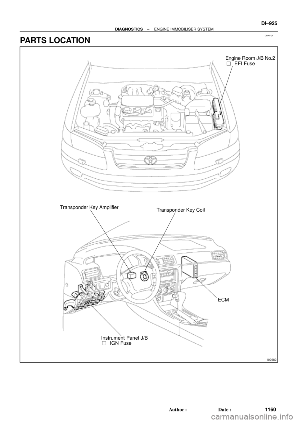
DI1KI±04
I02682
Engine Room J/B No.2
��EFI Fuse
Transponder Key Amplifier
Transponder Key Coil
ECM
��IGN Fuse Instrument Panel J/B
± DIAGNOSTICSENGINE IMMOBILISER SYSTEM
DI±925
1160 Author�: Date�:
PARTS LOCATION