Page 2588 of 4770
DI±168
± DIAGNOSTICSENGINE (5S±FE)
403 Author�: Date�:
8 Check for open and short in harness and connector between ignition switch and
ignition coils (See page IN±31).
NG Repair or replace harness or connector.
OK
9 Check ignition coil (See page IG±5).
NG Replace ignition coil.
OK
10 Check EFI main relay (Marking: EFI) (See page SF±40).
NG Replace EFI main relay.
OK
Replace igniter.
Page 2599 of 4770
A07554
ECM
+B 12
E7 B±Y J/C
B
J28 J27B
B±Y
Instrument
Panel J/B 22J 2K7
W±R EFI
Relay 1 3
52
2F4
W±B
2A 1
AM2
42L
B
FL
Block
MAIN
FL
B±GEngine
J/B No.2
5
1B
531K71W
IGN
1K
Room
W±R
IG
Switch
7 6
14
E9
BR
B±R
EC
E1
F6
F4EB
B±R
1
1
EFI
J23
J/C A
A
Battery
BR
(*2) (*1)
*1: w/ Immobiliser
*2: w/o ImmobiliserE924 (*2)
MREL 7
E10 B±Y (*1) 6II4 B±W (*1)
± DIAGNOSTICSENGINE (5S±FE)
DI±179
414 Author�: Date�:
ECM Power Source Circuit
CIRCUIT DESCRIPTION
When the ignition switch is turned ON, battery positive voltage is applied to the coil, closing the contacts of
the EFI main relay (Marking: EFI) and supplying power to terminal +B of the ECM.
WIRING DIAGRAM
DI01L±05
Page 2603 of 4770
A00325
BatteryMAIN IG Switch
AM2EFI
MAIN
FLStarter ST RelayPark/Neutral Position Switch
(Clutch Start Switch)EFI RelayCIR OPN Relay
Fuel Pump
ECM
FC
Tr
STA
NE (STA Signal)
(NE Signal) IGN
STARTER ST
± DIAGNOSTICSENGINE (5S±FE)
DI±183
418 Author�: Date�:
Fuel Pump Control Circuit
CIRCUIT DESCRIPTION
In the diagram below, when the engine is cranked, current flows from terminal ST of the ignition switch to
the starter relay coil and also current flows to terminal STA of ECM (STA signal).
When the STA signal and NE signal are input to the ECM, Tr is turned ON, current flows to coil of the circuit
opening relay, the relay switches on, power is supplied to the fuel pump and the fuel pump operates.
While the NE signal is generated (engine running), the ECM keeps Tr ON (circuit opening relay ON) and the
fuel pump also keeps operating.
DI01M±05
Page 2623 of 4770
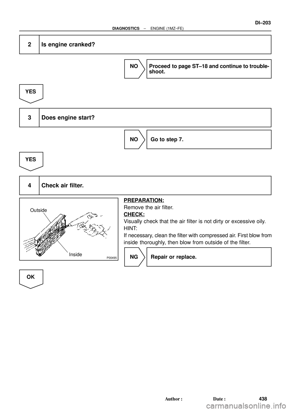
P00495
Outside
Inside
± DIAGNOSTICSENGINE (1MZ±FE)
DI±203
438 Author�: Date�:
2 Is engine cranked?
NO Proceed to page ST±18 and continue to trouble-
shoot.
YES
3 Does engine start?
NO Go to step 7.
YES
4 Check air filter.
PREPARATION:
Remove the air filter.
CHECK:
Visually check that the air filter is not dirty or excessive oily.
HINT:
If necessary, clean the filter with compressed air. First blow from
inside thoroughly, then blow from outside of the filter.
NG Repair or replace.
OK
Page 2626 of 4770
P23917
DI±206
± DIAGNOSTICSENGINE (1MZ±FE)
441 Author�: Date�:
8 Check for spark.
PREPARATION:
(a) Remove the ignition coil or disconnect the high±tension
cord from the spark plug.
(b) Remove the spark plug.
(c) Install the spark plug to the ignition coil or high±tension
cord.
(d) Disconnect the injector connector.
(e) Hold the end about 12.5 mm (0.5 in.) from the ground.
CHECK:
Check if spark occurs while engine is being cranked.
NOTICE:
To prevent excess fuel being injected from the injectors
during this test, don't crank the engine for more than 5 ~ 10
seconds at a time.
OK:
Spark jumps across electrode gap.
NG Proceed to page IG±1 and continue to
troubleshoot.
OK
Proceed to problem symptoms table on page
DI±221.
Page 2629 of 4770

DI±209
444 Author�: Date�:
(b) TOYOTA Enhanced Signals.
TOYOTA hand±held tester displayMeasurement ItemNormal Condition*
MISFIRE RPMEngine RPM for first misfire rangeM")
± DIAGNOSTICSENGINE (1MZ±FE)
DI±209
444 Author�: Date�:
(b) TOYOTA Enhanced Signals.
TOYOTA hand±held tester displayMeasurement ItemNormal Condition*
MISFIRE RPMEngine RPM for first misfire rangeMisfire 0: 0 rpm
MISFIRE LOADEngine load for first misfire rangeMisfire 0: 0 g/r
INJECTORFuel injection time for cylinder No.1Idling: 1.6 ~ 2.9 ms
IAC DUTY RATIOIntake Air Control Valve Duty Ratio
Opening ratio rotary solenoid type IAC valveIdling: 27 ~ 47 %
STARTER SIGStarter SignalCranking: ON
CTP SIGClosed Throttle Position SignalThrottle Fully Closed: ON
A/C SIGA/C Switch SignalA/C ON: ON
PNP SWPark/Neutral Position Switch SignalP or N position: ON
ELCTRCL LOAD SIGElectrical Load SignalDefogger switch ON: ON
STOP LIGHT SWStop Light Switch SignalStop light switch ON: ON
PS OIL PRESS SWPower Steering Oil Pressure Switch SignalTurn steering wheel: ON
FC IDLFuel Cut Idle: Fuel cut when throttle valve fully
closed, during decelerationFuel cut operating: ON
FC TAUFuel Cut TAU: Fuel cut during very light loadFuel cut operating: ON
CYL#1 ~ CYL#6Abnormal revolution variation for each cylinder0%
IGNITIONTotal number of ignition for every 1,000 revolu-
tions0 ~ 3,000
EGRT GASEGR Gas Temperature Sensor Value
EGR not operating:
Temperature between intake air temp. and
engine coolant temp.
INTAKE CTRL VSVIntake Air Control Valve VSV SignalVSV operating: ON
EGR SYSTEMEGR system operating conditionIdling: OFF
A/C CUT SIGA/C Cut SignalA/C S/W OFF: ON
FUEL PUMPFuel Pump SignalIdling: ON
EVAP (PURGE) VSVEVAP VSV SignalVSV operating: Above 30%
VAPOR PRESS VSVVapor Pressure VSV SignalVSV operating: ON (TANK)
*: If no conditions are specifically stated for ºldlingº, it means the shift lever is at N or P position, the A/C switch
is OFF and all accessory switches are OFF.
Page 2699 of 4770

DI±279
514 Author�: Date�:
2 Check spark plug and spark of misfiring cylinder.
PREPARATION:
(a) Remove the ignition coil (See page IG±7).
(b) Remov")
A00221P25779
P23917
± DIAGNOSTICSENGINE (1MZ±FE)
DI±279
514 Author�: Date�:
2 Check spark plug and spark of misfiring cylinder.
PREPARATION:
(a) Remove the ignition coil (See page IG±7).
(b) Remove the spark plug.
CHECK:
(a) Check spark plug type.
(b) Check for carbon deposits on electrode.
(c) Check electrode gap.
OK:
(a) Twin ground electrodes type.
Recommended spark plug:
ND PK20TR11
NGK BKR6EKPB±11
(b) No large carbon deposit present.
Not wet with gasoline or oil.
(c) Electrode gap:
Standerd: 1.0 ± 1.1 mm (0.03937 ± 0.043 in.).
Maximum: 1.3 mm (0.051 in.).
PREPARATION:
(a) Install the spark plug to the ignition coil, and connect the
ignition coil the connector.
(b) Disconnect injector connector.
(c) Hold the end about 12.5 mm (0.5 in.) from the ground.
CHECK:
Check if spark occurs while engine is being cranked.
NOTICE:
To prevent excess fuel being injected from the
injectors during this test, don't crank the engine for more
than 5 ~ 10 sec. at a time.
OK:
Spark jumps across electrode gap.
NG Replace or check ignition system
(See page IG±1).
OK
Page 2707 of 4770

DI±287
522 Author�: Date�:
DTC P0335 Cranksh")
P25474
Camshaft Position Sensor
1
2
1
2B±W
B±RL
BR LECM
G22+
NE+
NE±
E2
E10
E10E11
2410
Crankshaft Position SensorB±R16
± DIAGNOSTICSENGINE (1MZ±FE)
DI±287
522 Author�: Date�:
DTC P0335 Crankshaft Position Sensor ºAº Circuit
Malfunction
CIRCUIT DESCRIPTION
Crankshaft position sensor (NE signal) consists of a signal plate and pickup coil.
The NE signal plate has 34 teeth and is mounted on the crankshaft. The NE signal sensor generates 34
signals for every engine revolution. The ECM detects the standard crankshaft angle based on the G22 sig-
nals, and the actual crankshaft angle and the engine speed by the NE signals.
DTC No.DTC Detecting ConditionTrouble Area
P0335
No crankshaft position sensor signal to ECM during cranking
(2 trip detection logic)�Open or short in crankshaft position sensor circuit
�Crankshaft position sensor
P0335No crankshaft position sensor signal to ECM with engine
speed 600 rpm or more (2 trip detection logic)
�Crankshaft osition sensor
�Starter
�ECM
WIRING DIAGRAM
INSPECTION PROCEDURE
HINT:
�Perform troubleshooting of DTC P0335 first. If no trouble is found, troubleshoot the following mechani-
cal systems.
�Read freeze frame data using TOYOTA hand±held tester or OBD II scan tool. because freeze frame
records the engine conditions when the malfunction is detected, when troubleshooting it is useful for
determining whether the vehicle was running or stopped, the engine warmed up or not, the air±fuel
ratio lean or rich, etc. at the time of the malfunction.
DI07U±06


EFI RelayCIR OPN Relay
Fuel Pump
ECM
FC
Tr
STA
NE (STA Signal)
(NE Signal) IGN
STARTER ST
�")