Page 2140 of 4770

BE0AJ±03
Z18937
Connector ºAº Connector ºBº Connector ºCº
Connector ºAº
Connector ºBº
Connector ºCº
J±13±1±A J±16±1 J±13±1
1 2 3 4 5 6 7 8 9 10 11 12 1314 15 16 1 234 56 78 910111213 1 23456 78910111213
C7
C5
A2 B3
A1
C8
B15
C6
B6
A4
C4
B5
C10 B14
A13
B2
C1
B1
C9
A6
A11
A7
A10
A8
A9
C13
B8
B11
B12A5
C11
B4
B16 C2
A12
A3
B7
C3
C12
B9
B10
B13 F
E
T
S
ODOMETER
Fuel Level Warning
Seat Belt Warning
ABS Warning
Low Oil Pressure Warning
Cruise Control Indicator
Malfunction Indicator
O/D OFF Indicator
Light Failure Warning
Brake Warning
SLIP Indicator
TRAC Indicator
Washer Level Warning
Discharge Warning
Right Turn Indicator
Left Turn Indicator
Security Indicator
L
2
D
N
R
P
Illumination
Hi±Beam Indicator
Open Door Warning
SRS Warning
: Fuel Gauge
: Engine Coolant Temperature Gauge
: Tachometer
: Speedometer
No.
A
B
C1
2
3
4
5
6
7 8
9
10
11
12 13
14
15
16
2 3
4
5
6
7 8
9
10
11 12
131
2
3
4 5
6
7
8
9
10
11
12
13
F
E
T
SEngine coolant temperature sender gauge
Ground
Light failure sensor
Integration relay
Traction ECU
Park/neutral position switch (A/T)
O/D OFF switch (A/T)
IGN fuse
Turn signal switch
ST relay
Fuel sender gauge
Generator
Oil pressure switch
Fuel sender gauge
Parking brake switch and brake fluid level warning switch
Headlight dimmer switch
Headlight dimmer switch
Door courtesy switch
DOME fuse
ECU±B fuse
Airbag sensor assembly
ECM
No.1 Vehicle speed sensor Ground
Turn signal switch ECM
Traction ECU
ABS ECU
Ground No.1 Vehicle speed sensor
GAUGE fuse
Igniter
Security ECU
Cruise control ECU
Washer fluid level warning switch
Light control rheostat
TAIL fuse Park/neutral position switch (A/T) Park/neutral position switch (A/T) Park/neutral position switch (A/T) Park/neutral position switch (A/T)
Park/neutral position switch (A/T)Wire Harness Side
Bulb Check
Relay
N20107 N201081
BE±46
± BODY ELECTRICALCOMBINATION METER
2266 Author�: Date�:
CIRCUIT
Page 2144 of 4770

N20216
C
B
A
N21646
Z14205
Warning Light
Ignition
Switch
Battery
1 BE±50
± BODY ELECTRICALCOMBINATIO")
Z15788
Engine coolant temperature gauge
Ignition
Switch
BatteryWire Harness SideTest Bulb
(3.4 W)
N20216
C
B
A
N21646
Z14205
Warning Light
Ignition
Switch
Battery
1 BE±50
± BODY ELECTRICALCOMBINATION METER
2270 Author�: Date�:
(c) Ground terminal on the wire harness side connector
through a 3.4±W test bulb.
(d) Turn the ignition switch ON, and check that the bulb lights
up and the receiver gauge needle moves to the hot side.
If operation is as specified, replace the sender gauge.
Then, recheck the system.
If operation is not as specified, measure the receiver gauge re-
sistance.
10. INSPECT ENGINE COOLANT TEMPERATURE RE-
CEIVER GAUGE RESISTANCE
Measure the resistance between terminals.
Tester connectionResistance (W) *
A ± BApprox. 175.7
A ± CApprox. 54.0
B ± CApprox. 229.7
*: This circuit includes the diode.
HINT:
Connect the test leads so that the current from the ohmmeter
can flow according to the above order.
If resistance value is not as specified, replace the receiver
gauge.
11. INSPECT ENGINE COOLANT TEMPERATURE SEND-
ER GAUGE RESISTANCE
Measure the resistance between the terminal and gauge body.
Temperature °C (°F)Resistance (W)
50 (122.0)274
120 (248.0)26.4
If resistance value is not as specified, replace the engine cool-
ant temperature sender gauge.
12. INSPECT LOW OIL PRESSURE WARNING LIGHT
(a) Disconnect the connector from the warning switch and
ground terminal on the wire harness side connector.
(b) Turn the ignition switch ON and check that the warning
light lights up.
If the warning light does not light up, test the bulb.
Page 2145 of 4770

N06640
BE1217
Warning Light
Ignition
Switch
Battery
N02346
OFF
ON
1 2
N01212
BE1217
Warning Light
Ignition
Switch
Battery
± BODY ELECTRICALCOMBINATION METER
BE±51
2271 Author�: Date�:
13. INSPECT LOW OIL PRESSURE SWITCH
(a) Disconnect the connector from the switch.
(b) Check that continuity exists between terminal and ground
with the engine stopped.
(c) Check that no continuity exists between terminal and
ground with the engine running.
HINT:
Oil pressure should be over 24.5 kPa (0.25 kgf/cm
2, 3.55 psi).
If operation is not as specified, replace the switch.
14. INSPECT BRAKE SYSTEM WARNING LIGHT
(a) Disconnect the connector from the brake fluid warning
switch.
(b) Release the parking brake pedal.
(c) Connect the terminals on the wire harness side of the lev-
el warning switch connector.
(d) Start the engine, check that the warning light lights up.
If the warning light does not light up, test the bulb or wire har-
ness.
15. INSPECT BRAKE FLUID LEVEL WARNING SWITCH
(a) Remove the reservoir tank cap and strainer.
(b) Disconnect the connector.
(c) Check that no continuity exists between the terminals with
the switch OFF (float up).
(d) Use syphon, etc. to take fluid out of the reservoir tank.
(e) Check that continuity exists between the terminals with
the switch ON (float down).
(f) Pour the fluid back in the reservoir tank.
If operation is not as specified, replace the switch.
16. INSPECT PARKING BRAKE SWITCH
(a) Check that continuity exists between the terminal and
switch body with the switch ON (switch pin released).
(b) Check that no continuity exists between the terminal and
switch body with the switch OFF (switch pin pushed in).
If operation is not as specified, replace the switch or inspect
ground point.
17. INSPECT WASHER FLUID LEVEL WARNING LIGHT
(a) Disconnect the connectors from the level warning switch
and parking brake switch.
(b) Connect terminals on the wire harness side connector of
the level warning switch connector.
(c) Remove the GAUGE fuse and turn the ignition switch ON,
and check that the warning light comes on.
If the warning light does not light up, test the bulb.
Page 2221 of 4770
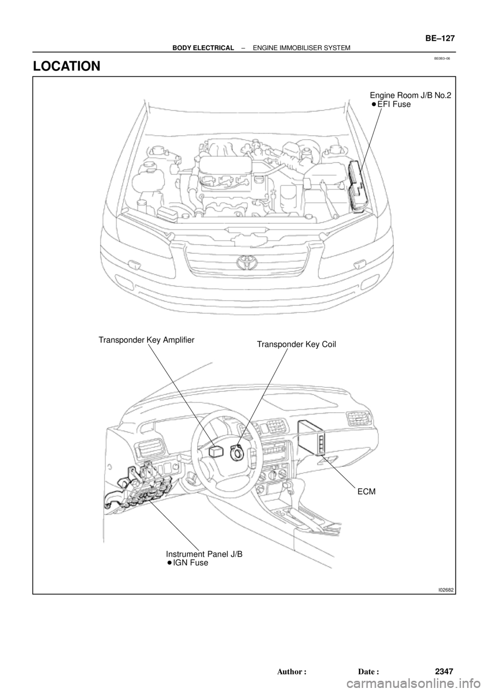
BE0B3±06
I02682
Engine Room J/B No.2
� EFI Fuse
Transponder Key Amplifier
Transponder Key Coil
ECM
� IGN Fuse Instrument Panel J/B
± BODY ELECTRICALENGINE IMMOBILISER SYSTEM
BE±127
2347 Author�: Date�:
LOCATION
Page 2222 of 4770
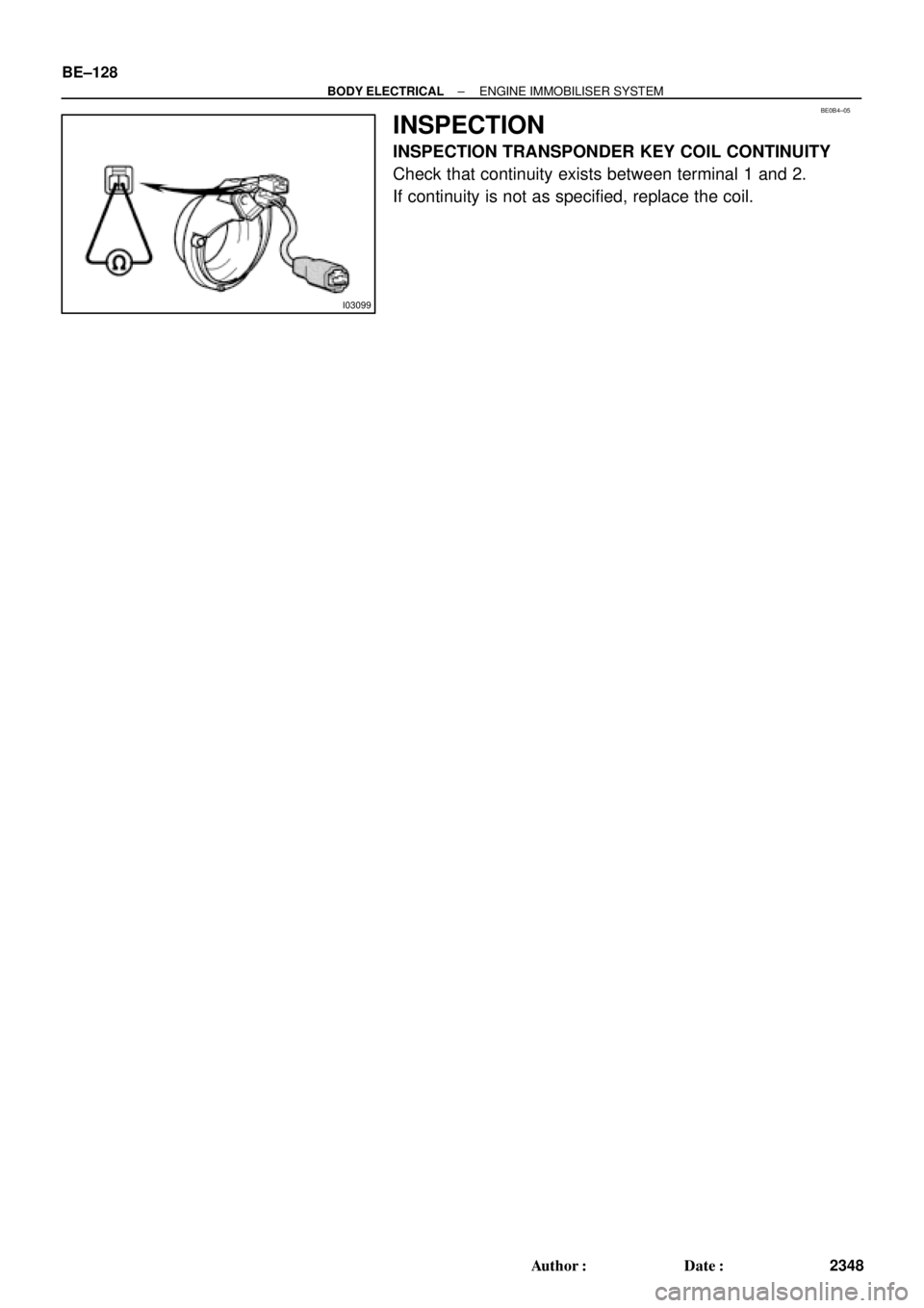
I03099
BE0B4±05
BE±128
± BODY ELECTRICALENGINE IMMOBILISER SYSTEM
2348 Author�: Date�:
INSPECTION
INSPECTION TRANSPONDER KEY COIL CONTINUITY
Check that continuity exists between terminal 1 and 2.
If continuity is not as specified, replace the coil.
Page 2245 of 4770
 1MZ±FE engine:
Install a pad wear indicator plate on the inner pad.
(b) Apply disc brake grease to both sides of the inner anti±")
R00595
R02981
± BRAKEFRONT BRAKE PAD
BR±23
2046 Author�: Date�:
(a) 1MZ±FE engine:
Install a pad wear indicator plate on the inner pad.
(b) Apply disc brake grease to both sides of the inner anti±
squeal shims (See page BR±21).
(c) Install the 2 anti±squeal shims on each pad.
(d) Install inner pad with the pad wear indicator plate facing
upward.
(e) Install inner pad.
(f) Install outer pad.
NOTICE:
There should be no oil or grease adhering to the friction
surfaces of the pads or the disc.
(g) 5S±FE engine:
Install the 2 anti±squeal springs.
13. INSTALL CALIPER
(a) Draw out a small amount of brake fluid from the reservoir.
(b) Press in the piston with a hammer handle or similar imple-
ment.
HINT:
If the piston is difficult to push in, loosen the bleeder plug and
push in the piston while letting some brake fluid escape.
(c) Install the caliper.
(d) 5S±FE engine:
Hold the sliding pin and torque the installation bolt.
(e) 1MZ±FE engine:
Install the installation bolt.
Torque: 34 N´m (350 kgf´cm, 25 ft´lbf)
(f) Install the flexible hose and bolt to the bracket.
Torque: 29 N´m (300 kgf´cm, 21 ft´lbf)
14. INSTALL FRONT WHEEL
Torque: 103 N´m (1,050 kgf´cm, 76 ft´lbf)
15. DEPRESS BRAKE PEDAL SEVERAL TIMES
16. CHECK THAT FLUID LEVEL IS AT MAX LINE
Page 2327 of 4770

CL034±01
± CLUTCHTROUBLESHOOTING
CL±1
1780 Author�: Date�:
TROUBLESHOOTING
PROBLEM SYMPTOMS TABLE
Use the table below to help you find the cause of the problem. The numbers indicate the priority of the likely
cause of the problem. Check each part in order. If necessary, replace these parts.
SymptomSuspect AreaSee page
1. Engine mounting (Loosen)±1. Engine mounting (Loosen)
2. Clutch disc (Runout is excessive)
±
CL±17
2. Clutch disc (Runout is excessive)
3. Clutch disc (Oily)
CL±17
CL±17
Clutch grabs/chatters
3. Clutch disc (Oily)
4. Clutch disc (Worn out)
CL±17
CL±17Clutch grabs/chatters4. Clutch disc (Worn out)
5. Clutch disc torsion rubber (Damaged)
CL±17
CL±175. Clutch disc torsion rubber (Damaged)
6. Clutch disc (Glazed)
CL 17
CL±176. Clutch disc (Glazed)
7. Diaphragm spring (Out of tip alignment)
CL 17
CL±19
1. Clutch line (Air in line)±
Clutch pedal spongy
1. Clutch line (Air in line)
2. Master cylinder cup (Damaged)
±
CL±4
Clutch edal s ongy2. Master cylinder cu (Damaged)
3. Release cylinder cup (Damaged)
CL 4
CL±9
1 Release bearing (Worn dirty or damaged)CL 19Clutch noisy1. Release bearing (Worn, dirty, or damaged)
2Cl hdi i bb (D d)
CL±19
CL 17Clutch noisy2. Clutch disc torsion rubber (Damaged)CL±17
1. Clutch pedal (Freeplay out of adjustment)CL±21. Clutch edal (Free lay out of adjustment)
2. Clutch disc (Oily)
CL±2
CL±17
Cl t h li
2. Clutch disc (Oily)
3. Clutch disc (Worn out)
CL±17
CL±17Clutch slips3. Clutch disc (Worn out)
4. Diaphragm spring (Damaged)
CL 17
CL±174. Dia hragm s ring (Damaged)
5. Pressure plate (Distortion)
CL 17
CL±175. Pressure late (Distortion)
6. Flywheel (Distortion)
CL 17
±
1 Clutchpedal (Freeplay out of adjustment)CL±21. Clutch pedal (Freeplay out of adjustment)
2 Clutch line (Air in line)CL±2
2. Clutch line (Air in line)
3 Master cylinder cup(Damaged)
±
CL 43. Master cylinder cup (Damaged)
4 Release cylinder cup(Damaged)
CL±4
CL 94. Release cylinder cup (Damaged)
5 Clutch disc (out of true)
CL±9
CL 175. Clutch disc (out of true)
6 Cl tch disc (R no t is e cessi e)
CL±17
CL 17
Cl t h d t di
6. Clutch disc (Runout is excessive)
7 Cl t h di (Li i b k )
CL±17
CL 17Clutch does not disengage7. Clutch disc (Lining broken)
8 Cl t h di (Di t b d)
CL±17
CL 178. Clutch disc (Dirty or burned)
Cl h di (Oil )
CL±17
CL9. Clutch disc (Oily)CL±17
10. Clutch disc (Lack of spline grease)CL±19
11. Diaphragm spring (Damaged)CL±17gg(g)
12. Diaphragm spring (Out of tip alignment)CL±19gg( g)
13. Pressure plate (Distortion)CL±17
Page 2349 of 4770
CO066±03
± COOLING (5S±FE)COOLANT
CO±1
1575 Author�: Date�:
COOLANT
INSPECTION
HINT:
Check the coolant level when the engine is cold.
1. CHECK ENGINE COOLANT LEVEL AT RADIATOR RESERVOIR
The engine coolant level should be between the ºLOWº and ºFULLº lines.
If low, check for leaks and add ºToyota Long Life Coolantº or equivalent up to the ºFULLº line.
2. CHECK ENGINE COOLANT QUALITY
(a) Remove the radiator cap.
CAUTION:
To avoid the danger of being burned, do not remove the radiator cap while the engine and radiator
are still hot, as fluid and steam can be blown out under pressure.
(b) There should not be any excessive deposits of rust or scale around the radiator cap or radiator filler
hole, and the coolant should be free from oil.
If excessively dirty, replace the coolant.
(c) Reinstall the radiator cap.