Page 1570 of 4770

AC±48
± AIR CONDITIONINGCOMPRESSOR AND MAGNETIC CLUTCH
2530 Author�: Date�:
5. 1MZ±FE engine models:
CONNECT DISCHARGE HOSE
Connect the discharge hose with the bolt.
Torque: 10 N´m (100 kgf´cm, 7 ft´lbf)
NOTICE:
Hoses should be connected immediately after the caps
have been removed.
HINT:
Lubricate a new O±ring with compressor oil and install the tube.
6. INSTALL SUCTION HOSE
(a) Install the suction hose and tighten the bolt and nut.
Torque:
Piping joint: 32 N´m (330 kgf´cm, 24 ft´lbf)
Block joint: 10 N´m (100 kgf´cm, 7 ft´lbf)
HINT:
Lubricate 2 new O±rings with compressor oil and install the
hose.
(b) Install the suction hose clamping bolt.
(c) Connect the wire harness clamp.
7. INSTALL AND CHECK DRIVE BELT
(See page AC±18, AC±16)
8. CONNECT NEGATIVE (±) TERMINAL CABLE TO BAT-
TERY
9. EVACUATE AIR FROM REFRIGERATION SYSTEM
AND CHARGE SYSTEM WITH REFRIGERANT
Specified amount: 800 ± 50 g (28.22 ± 1.76 oz.)
10. INSPECT FOR LEAKAGE OF REFRIGERANT
Using a gas leak detector, check for leakage of refrigerant.
If there is leakage, check the tightening torque at the joints.
11. INSPECT A/C OPERATION
Page 1576 of 4770
N20451
AC±54
± AIR CONDITIONINGCONDENSER
2536 Author�: Date�:
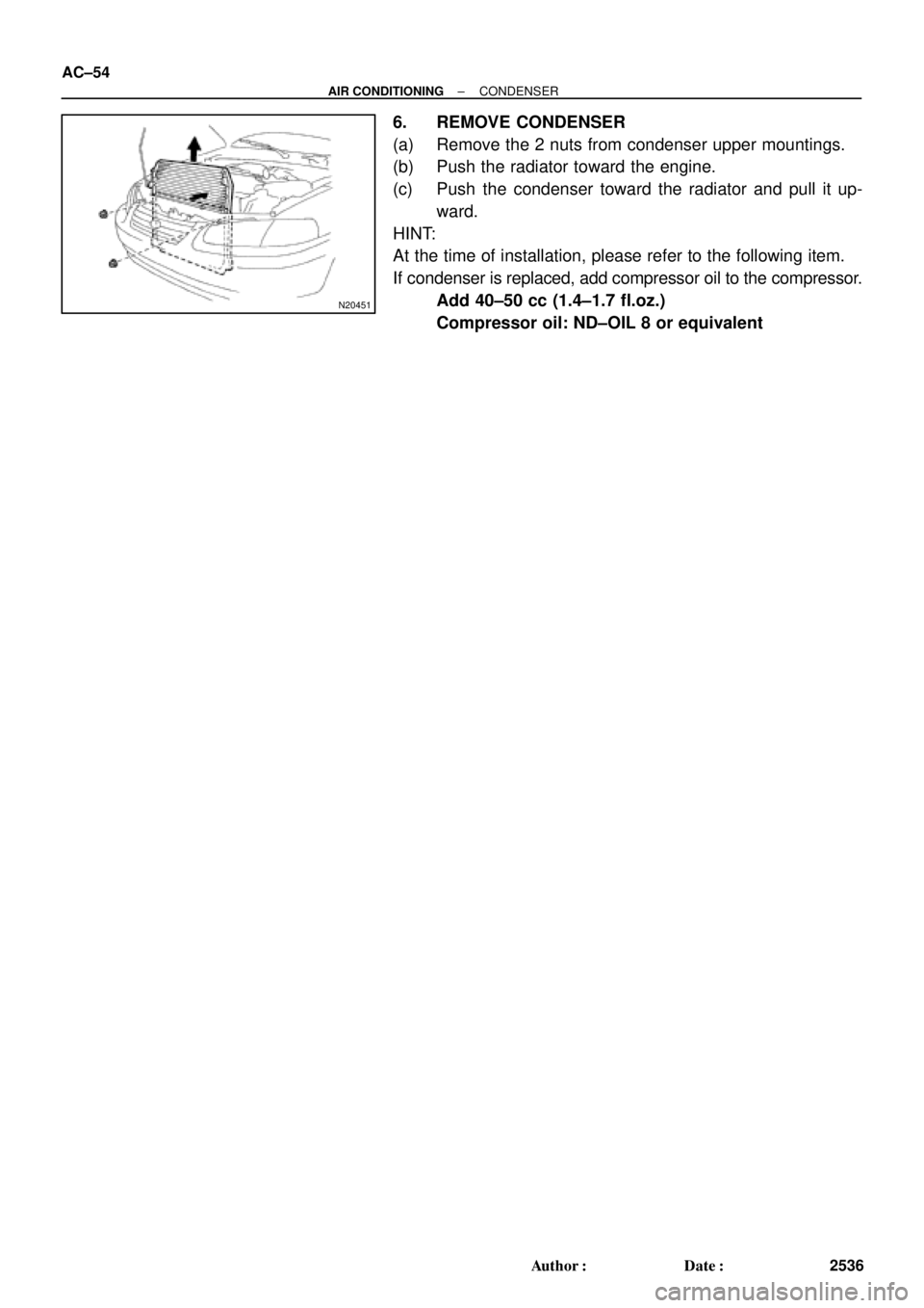
6. REMOVE CONDENSER
(a) Remove the 2 nuts from condenser upper mountings.
(b) Push the radiator toward the engine.
(c) Push the condenser toward the radiator and pull it up-
ward.
HINT:
At the time of installation, please refer to the following item.
If condenser is replaced, add compressor oil to the compressor.
Add 40±50 cc (1.4±1.7 fl.oz.)
Compressor oil: ND±OIL 8 or equivalent
Page 1775 of 4770
AX03G±01
Q10053
14 (145, 10)
No.1 Exhaust Pipe Support BracketClip Engine Hood
Air Cleaner Assembly
14 (145, 10)
Starter
Cruise Control Actuator
RH Drive Shaft
42 (430, 31)66 (670, 48)
39 (400, 29)
39 (400, 29)
39 (400, 29)
Hold Down Clamp
Manifold Stay
Stiffener
PlateBattery
Battery Tray � Snap Ring
�
32 (330, 24)
27 (280, 20)
Torque Converter
Clutch
x6
42 (430, 31)
42 (430, 31)
Stiffener Plate66 (670, 48)
42 (430, 31)
Exhaust
Manifold Stay66 (670, 48)
� Snap RingLH Drive Shaft
Plug for Line Pressure Test
Rear End Plate
15 (150, 11)
19 (195, 14)
25 (250, 18)
Oil Pan Insulator Shift Control Cable
N´m (kgf´cm, ft´lbf): Specified torque
� Non±reusable partTMMK
TMC
± AUTOMATIC TRANSAXLE (A140E)AUTOMATIC TRANSAXLE UNIT
AX±17
1910 Author�: Date�:
AUTOMATIC TRANSAXLE UNIT
COMPONENTS
Page 1777 of 4770
AUTOMATIC TRANSAXLE UNIT
AX±19
1912 Author�: Date�:
REMOVAL
1. REMOVE BATTERY
2. REMOVE AIR CLEANER ASSEMBLY
3. DISCONNECT THROTTLE")
AX03H±01
Q10055
Q00211
Q10056
Q10057
± AUTOMATIC TRANSAXLE (A140E)AUTOMATIC TRANSAXLE UNIT
AX±19
1912 Author�: Date�:
REMOVAL
1. REMOVE BATTERY
2. REMOVE AIR CLEANER ASSEMBLY
3. DISCONNECT THROTTLE CABLE
4. w/ CRUISE CONTROL:
REMOVE CRUISE CONTROL ACTUATOR
(a) Disconnect the connector.
(b) Remove the 3 bolts and disconnect cruise control actua-
tor with the bracket.
5. DISCONNECT OIL COOLER HOSE
6. DISCONNECT VEHICLE SPEED SENSOR CONNEC-
TOR
7. DISCONNECT PARK/NEUTRAL POSITION SWITCH
CONNECTOR
8. DISCONNECT SHIFT SOLENOID VALVE NO.1 AND
NO.2 CONNECTOR
9. DISCONNECT SHIFT SOLENOID VALVE SL CONNEC-
TOR
10. REMOVE 2 FRONT SIDE ENGINE MOUNTING BOLTS
Torque:
TMC made: 80 N´m (820 kgf´cm, 59 ft´lbf)
TMMK made:
Green color bolt: 66 N´m (670 kgf´cm, 48 ft´lbf)
Silver color bolt: 44 N´m (450 kgf´cm, 32 ft´lbf)
11. DISCONNECT 2 GROUND CABLES
12. REMOVE STARTER
(a) Disconnect the connector and remove the nut.
(b) Remove the 2 bolts, shift cable clamp and starter.
Torque: 39 N´m (400 kgf´cm, 29 ft´lbf)
13. REMOVE 3 TRANSAXLE±TO±ENGINE BOLTS
Torque: 66 N´m (670 kgf´cm, 48 ft´lbf)
Page 1815 of 4770
AUTOMATIC TRANSAXLECOMPONENT PARTS REMOVAL ±
AX±19
22. STAND TRANSAXLE ENGINE SIDE UPWARD
23. REMOVE OIL PUMP
NOTICE: Before removing the oil pump, remove the se-
cond coast brake piston.
(a) Remove the 7 bolts.
(b) Using SST, pull out the oil pump from the transaxle case.
SST 09350±32014
24. REMOVE O±RING FROM OIL PUMP
25. REMOVE DIRECT CLUTCH AND FORWARD CLUTCH
26. SEPARATE DIRECT CLUTCH AND FORWARD
CLUTCH
(a) Separate the direct clutch and forward clutch.
(b) Remove the thrust washer from direct clutch.
Page 1954 of 4770
Q10027
Q10071
Q10034
Q10035
Q10040
AX±26
± AUTOMATIC TRANSAXLE (A541E)AUTOMATIC TRANSAXLE UNIT
1946 Author�: Date�:
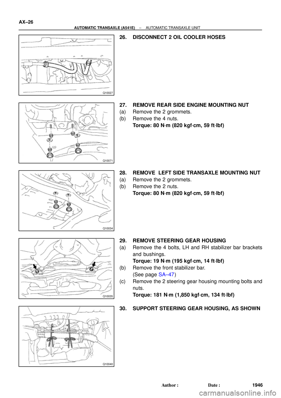
26. DISCONNECT 2 OIL COOLER HOSES
27. REMOVE REAR SIDE ENGINE MOUNTING NUT
(a) Remove the 2 grommets.
(b) Remove the 4 nuts.
Torque: 80 N´m (820 kgf´cm, 59 ft´lbf)
28. REMOVE LEFT SIDE TRANSAXLE MOUNTING NUT
(a) Remove the 2 grommets.
(b) Remove the 2 nuts.
Torque: 80 N´m (820 kgf´cm, 59 ft´lbf)
29. REMOVE STEERING GEAR HOUSING
(a) Remove the 4 bolts, LH and RH stabilizer bar brackets
and bushings.
Torque: 19 N´m (195 kgf´cm, 14 ft´lbf)
(b) Remove the front stabilizer bar.
(See page SA±47)
(c) Remove the 2 steering gear housing mounting bolts and
nuts.
Torque: 181 N´m (1,850 kgf´cm, 134 ft´lbf)
30. SUPPORT STEERING GEAR HOUSING, AS SHOWN
Page 2100 of 4770

BE±6
± BODY ELECTRICALBODY ELECTRICAL SYSTEM
2226 Author�: Date�:
Washer fluid does not operate.1. Washer Hose and Nozzle±
� In wiper switch HI position, the wiper blade is in contact with
the body.
� When the wiper switch is OFF, the wiper blade does not
retract or the retract position is wrong.1. *1Wiper Switch
2. Wire HarnessBE±40
±
COMBINATION METER
METER, GAUGES AND ILLUMINATION:
SymptomSuspect AreaSee page
Tachometer, Fuel Gauge and Engine Coolant Temperature Gauge
do not operate.1. GAUGE Fuse (I/P J/B No.1)
2. Meter Circuit Plate
3. Wire Harness±
BE±46
±
Speedometer does not operate.
1. No.1 Vehicle Speed Sensor
2. Meter Circuit Plate
3. Wire HarnessBE±47
BE±46
±
Tachometer does not operate.
1. Igniter (5S±FE)
(1MZ±FE)
2. Meter Circuit Plate
3. Wire HarnessIG±1
IG±1
BE±46
±
Fuel Gauge does not operate or abnormal operation.
1. Fuel Receiver Gauge
2. Fuel Sender Gauge
3. Meter Circuit Plate
4. Wire HarnessBE±47
BE±47
BE±46
±
Engine Coolant Temperature Gauge does not operate or abnormal
operation
1. Engine Coolant Temperature Receiver Gauge
2. Engine Coolant Temperature Sender Gauge
3. Meter Circuit Plate
4. Wire HarnessBE±47
BE±47
BE±46
±
All illumination lights do not light up.
1. TAIL Fuse (I/P J/B No.1)
2. Light Control Rheostat
3. Wire Harness±
BE±47
±
Brightness does not change even when rheostat turned.1. Bulb
2. Wire Harness±
±
Only one illumination light does not light up.1. Bulb
2. Wire Harness±
±
COMBINATION METER
WARNING LIGHTS:
SymptomSuspect AreaSee page
Warning lights do not light up. (Except Discharge, Open Door and
SRS)1. GAUGE Fuse (I/P J/B No.1)
2. Meter Circuit Plate
3. Wire Harness±
BE±46
±
Low Oil Pressure warning light does not light up.
1. Bulb
2. Low Oil Pressure Warning Switch
3. Meter Circuit Plate
4. Wire Harness±
BE±47
BE±46
±
Fuel Level warning light does not light up.
1. Bulb
2. Fuel Level Warning Switch
3. Meter Circuit Plate
4. Wire Harness±
BE±47
BE±46
±
ABS warning light does not light up.
1. Bulb
2. ABS ECU
3. Wire Harness±
IN±31
±
Page 2139 of 4770
Z19055
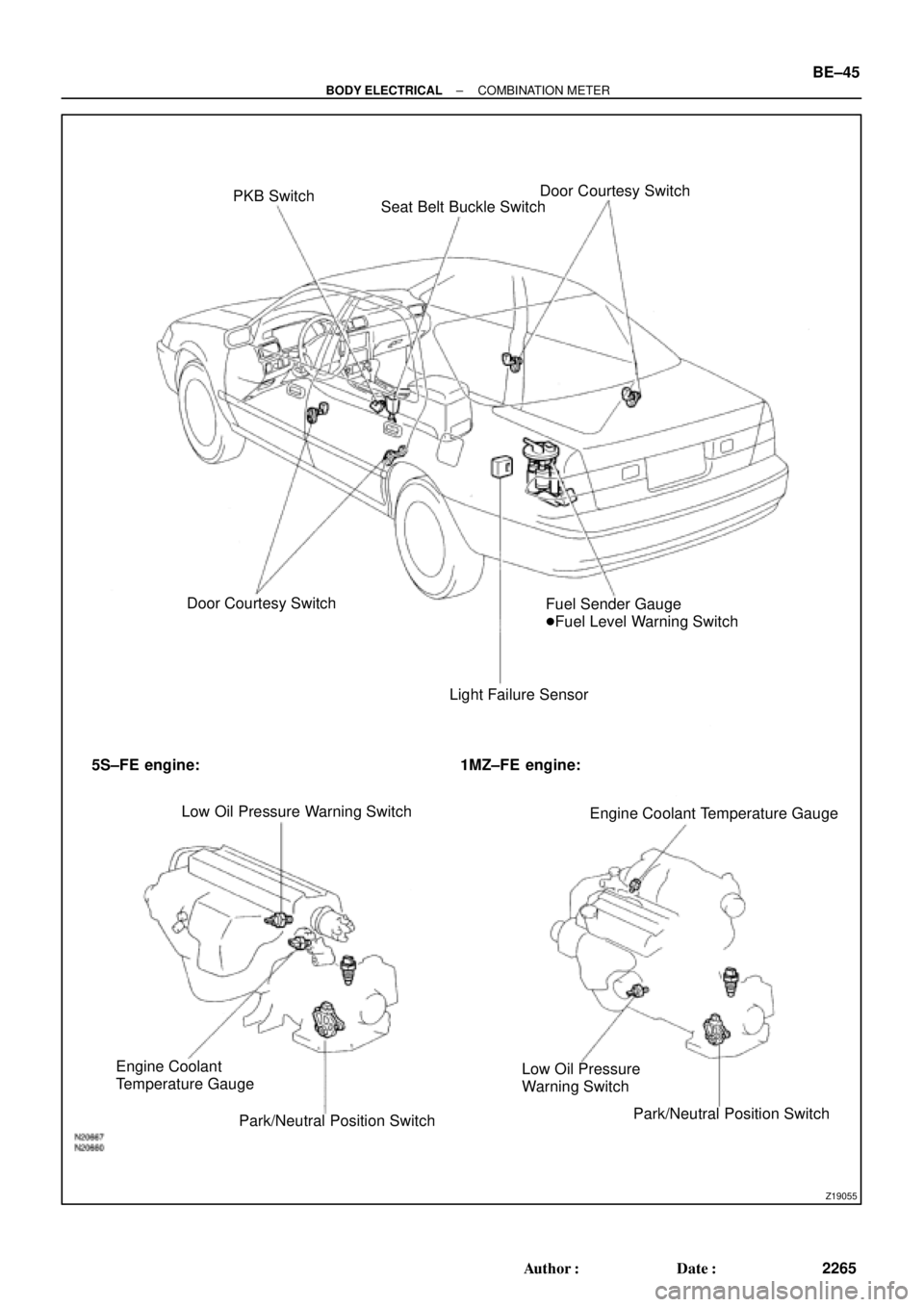
PKB Switch
Seat Belt Buckle SwitchDoor Courtesy Switch
Door Courtesy Switch
Light Failure SensorFuel Sender Gauge
�Fuel Level Warning Switch
5S±FE engine: 1MZ±FE engine:
Low Oil Pressure Warning Switch
Engine Coolant Temperature Gauge
Engine Coolant
Temperature Gauge
Park/Neutral Position SwitchLow Oil Pressure
Warning Switch
Park/Neutral Position Switch
± BODY ELECTRICALCOMBINATION METER
BE±45
2265 Author�: Date�:

No.1 Exhaust Pipe Support BracketClip Engine Hood
Air Cleaner Assembly
14 (145, 10)
Starter
Cruise Control Actuator
RH Drive Shaft
42 (430, 31)66 (670, 48)
39 (400, 29)
3")
 Remove")