Page 2445 of 4770

A02958
E7ECM Terminals
E9E8E10
11
19
1412 10 9 8
7652
43
18 21 22
20
16151
13
17 11 14
109
87 652 4
3
21 2220
16 15 131
12 11 1 09
652
43 1 12
7 8
19
14
109 8
7652
43
18
23 2416
151
17
11 12 13 25
26
± DIAGNOSTICSENGINE (5S±FE)
DI±25
260 Author�: Date�:
With engine immobiliser system
Symbols (Terminals No.)Wiring ColorConditionSTD Voltage (V)
BATT (E7 ± 2) ± E1 (E9 ± 24)B ± Y e BRAlways9 ~ 14
+ B (E7 ± 12) ± E1 (E9 ± 24)B ± Y e BRIG switch ON9 ~ 14
VC (E8 ± 1) ± E2 (E8 ± 9)Ye BRIG switch ON4.5 ~ 5.5
VTA (E8 10) E2 (E8 9)LGBR
IG switch ON
Throttle valve fully closed0.3 ~ 1.0
VTA (E8 ± 10) ± E2 (E8 ± 9)LG e BRIG switch ON
Throttle valve fully open3.2 ~ 4.9
PIM (E8 2) E2 (E8 9)BYBR
IG switch ON3.3 ~ 3.9
PIM (E8 ± 2) ± E2 (E8 ± 9)B ± Y e BRApply vacuum 26.7 kPa (200 mmHg, 7.9 in.Hg)2.5 ~ 3.1
THA (E8 ± 3) ± E2 (E8 ± 9)Y ± B e BRIdling, Intake air temp. 20°C (68° F)0.5 ~ 3.4
THW (E8 ± 4) ± E2 (E8 ± 9)G ± B e BRIdling, Engine coolant temp. 80°C (176°F) 0.2 ~ 1.0
STA (E7 11) E1 (E9 24)*1 GR e BRCranking6.0 or moreSTA (E7 ± 11) ± E1 (E9 ± 24) *2 B ± O e BRCranking6.0 or more
#10 (E9 12)IG switch ON9 ~ 14#10 (E9 ± 12)
± E01 (E9 ± 13) L e BRIdlingPulse generation
(See page DI±89)
#20 (E9 11)IG switch ON9 ~ 14#20 (E9 ± 11)
± E01 (E9 ± 13)R e BRIdlingPulse generation
(See page DI±89)
#30 (E9 10)IG switch ON9 ~ 14#30 (E9 ± 10)
± E01 (E9 ± 13)Y e BRIdlingPulse generation
(See page DI±89)
IG switch ON9 ~ 14
#40 (E9 ± 9) ± E01 (E9 ± 13)W e BRIdlingPulse generation
(See page DI±89)
IGT1 (E9 ± 23)
± E1 (E9 ± 24)B e BRIdlingPulse generation
(See page DI±163)
IGT2 (E9 ± 22)
± E1 (E9 ± 24)Y ± R e BRIdlingPulse generation
(See page DI±163)
IG switch ON, Disconnect ignition coil connector4.5 ~ 5.5
IGF (E9 ± 17) ± E1 (E9 ± 24)W ± R e BRIdlingPulse generation
(See page DI±163)
*1: TMC made
*2: TMMK made
Page 2513 of 4770

DI±93
328 Author�: Date�:
2 Check spark plug and spark of misfiring cylinder.
PREPARATION:
(a) Disconnect the high±tension cord from the spark plug.
(b) Remove")
A00434
± DIAGNOSTICSENGINE (5S±FE)
DI±93
328 Author�: Date�:
2 Check spark plug and spark of misfiring cylinder.
PREPARATION:
(a) Disconnect the high±tension cord from the spark plug.
(b) Remove the spark plug.
CHECK:
(a) Check the plug type.
(b) Check the electrode for carbon deposits.
(c) Check the electrode gap.
OK:
(a) Platinum±tipped spark plugs with twin ground
electrodes.
Recommended spark plug:
ND made: PK20TR11
NGK made: BKR6EKPB±11
(b) No large carbon deposit present.
Not wet with gasoline or oil.
(c) Electrode gap: 1.1 mm (0.043 in.)
PREPARATION:
(a) Install the spark plug to the high±tension code.
(b) Disconnect the injector connector.
(c) Ground the spark plug.
CHECK:
Check if spark occurs while the engine is being cracked.
NOTICE: To prevent excess fuel being injected from the in-
jectors during this test, don't crank the engine for more
than 5 ~ 10 seconds at a time.
OK:
Spark jumps across electrode gap.
NG Replace or check ignition system
(See page IG±1).
OK
Page 2520 of 4770
 (*2)
E10
E10
E1012 11
6
(*1) (*2)(*1) (*")
A03599
ECM
G+
NE+
NE±
E1 E9
E9
E95
4
17 B±W
L
B±R
L BR Camshaft Position Sensor
Crankshaft Position Sensor1
2
1
2
*1: w/o Immobiliser
*2: w/ Immobiliser(*1) (*2)
E10
E10
E1012 11
6
(*1) (*2)(*1) (*2)
B±R DI±100
± DIAGNOSTICSENGINE (5S±FE)
335 Author�: Date�:
DTC P0335 Crankshaft Position Sensor ºAº Circuit
Malfunction
CIRCUIT DESCRIPTION
Crankshaft position sensor (NE signal) consist of a signal plate and pickup coil.
The NE signal plate has 34 teeth and is mounted on the crankshaft. The NE signal sensor generates 34
signals of every engine revolution. The ECM detects the standard crankshaft angle based on the G signals,
and the actual crankshaft angle the engine speed by the NE signals.
DTC No.DTC Detecting ConditionTrouble Area
No crankshaft position sensor signal to ECM during cranking
(2 trip detection logic)�Open or short in crankshaft position sensor circuit.
C k h ft itiP0335No crankshaft position sensor signal to ECM with engine
speed 600 rpm or more
(2 trip detection logic)�Crankshaft position sensor
�Starter
�ECM
WIRING DIAGRAM
DI013±10
Page 2523 of 4770

DI±103
338 Author�: Date�:
DTC P0340 Camshaft Position Sensor Circuit
Malfunction
CIRCUIT DESCRIPTION
Camshaft position sensor (G signal) consist of signal plate and pic")
± DIAGNOSTICSENGINE (5S±FE)
DI±103
338 Author�: Date�:
DTC P0340 Camshaft Position Sensor Circuit
Malfunction
CIRCUIT DESCRIPTION
Camshaft position sensor (G signal) consist of signal plate and pickup coil.
The G signal plate has one tooth on its outer circumference and is mounted on the exhaust camshaft.
When the camshafts rotate, the protrusion on the signal plate and the air gap on the pickup coil change,
causing fluctuations in the magnetic field and generating an electromotive force in the pickup coil.
The NE signal plate has 34 teeth and is mounted on the crankshaft. The NE signal sensor generates 34
signals for every engine revolution. The ECM detects the standard crankshaft angle based on the G signals
and the actual crankshaft angle and the engine speed by the NE signals.
DTC No.DTC Detecting ConditionTrouble Area
P0340
No camshaft position sensor signal to ECM during cranking
(2 trip detection logic)�Open or short in camshaft position sensor circuit
�Camshaft position sensor
Di t ib tP0340No camshaft position sensor signal to ECM with engine speed
600 rpm or more�Distributor
�Starter
�ECM
WIRING DIAGRAM
Refer to DTC P0335 (Crankshaft Position Sensor ºAº Circuit Malfunction) on page DI±100.
DI014±09
Page 2583 of 4770

DI±163
398 Author�: Date�:
DTC P1300 Igniter Circuit Malfunction No.1
DTC P1310 Igniter Circuit Malfunction No.2
CIRCUIT DESCRIPTION
The ECM determines the ignition timi")
± DIAGNOSTICSENGINE (5S±FE)
DI±163
398 Author�: Date�:
DTC P1300 Igniter Circuit Malfunction No.1
DTC P1310 Igniter Circuit Malfunction No.2
CIRCUIT DESCRIPTION
The ECM determines the ignition timing, turns on Tr1 at a predetermined angle (°CA) before the desired
ignition timing and outputs and ignition signal (IGT) 1 to the igniter.
Since the width of the IGT signal is constant, the dwell angle control circuit in the igniter determines the time
the control circuit starts primary current flow to the ignition coil based on the engine rpm and ignition timing
one revolution ago, that is, the time the Tr2 turns on.
When it reaches the ignition timing, the ECM turns Tr1 off and outputs the IGT signal O.
This turns Tr2 off, interrupting the primary current flow and generating a high voltage in the secondary coil
which causes the spark plug to spark. Also, by the counter electromotive force generated when the primary
current is interrupted, the igniter sends an ignition confirmation signal (IGF) to the ECM. The ECM stops fuel
injection as a fail safe function when the IGF signal is not input to the ECM.
DTC No.DTC Detecting ConditionTrouble Area
P1300No IGF signal to ECM for 4 consecutive IGT1 signals during
engine running�Open or short in IGF or IGT circuit from igniter to ECM
�Ignition coil No.1 (Igniter No.1)
�ECM
P1310No IGF signal to ECM for 4 consecutive IGT2 signals during
engine running�Open or short in IGF or IGT circuit from igniter to ECM
�Ignition coil No.2 (Igniter No.2)
�ECM
HINT:
Ignition coil No.1 is for cylinder No.1 and No.4, and ignition coil No.2 is for cylinder No.2 and No.3.
DI01G±06
Page 2584 of 4770

A07122
IG Switch
B±R
BatteryEngine Room
J/B No.2
76B±R13
1II3B±R
B
BR
Spark Plug
Spark Plug
2
3 2
3 4
Tr2 Igniter
No.1
Ignition
Coil
No.1
FL Block
Y±R
BR
B
20
19
IGT2
Tr1
E9
E9
E9
W±R
IGT1
IGF5 V
Tr1
Ignition Coil
No.2
Igniter
No.2
AA A
EC
Tr2
W±R
B±R 5 51B 1K
Instrument
W±R
W±R
2L 2A
4 1
AM2B
F4 F6 1
1
B±G
MAIN FL
3 1
4
J/C J25
*1: w/o Immobiliser
*2: w/ Immobiliser(*1) (*2)
ECM
E9 23
E9 22
E9 17
(*1) (*2)
W±R
Panel J/BB
B
BR
BR J19
J/C
DI±164
± DIAGNOSTICSENGINE (5S±FE)
399 Author�: Date�:
WIRING DIAGRAM
INSPECTION PROCEDURE
HINT:
�If DTC P1300 is displayed, check ignition coil No.1 circuit.
�If DTC P1300 is displayed, check ignition coil No.2 circuit.
�Read freeze frame data using TOYOTA hand±held tester or OBD II scan tool. Because freeze frame
records the engine conditions when the malfunction is detected, when troubleshooting it is useful for
determining whether the vehicle was running or stopped, the engine warmed up or not, the air±fuel
ratio lean or rich, etc. at the time of the malfunction.
1 Check for spark plug and spark of misifining cylinder (See page DI±89).
NG Go to step 4.
OK
2 Check for open and short in harness and connector in IGF signal circuit between
ECM and ignition coils (See page IN±31).
NG Repair or replace harness or connector.
OK
Page 2585 of 4770
A03023A00417A03427
ON
IGF
(+)
w/o Immobiliser
w/ Immobiliser
IGF
(+)
± DIAGNOSTICSENGINE (5S±FE)
DI±165
400 Author�: Date�:
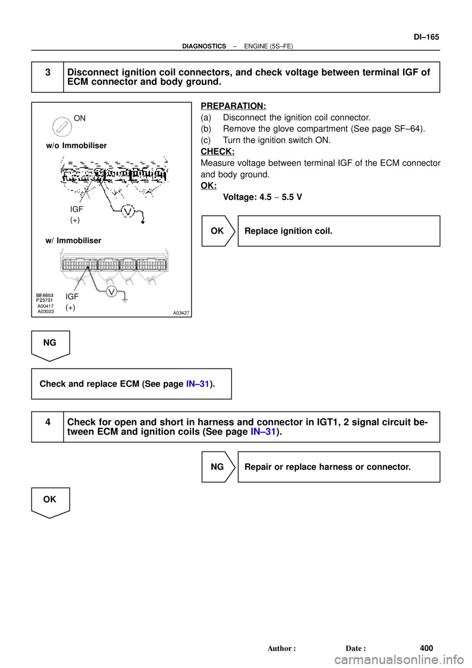
3 Disconnect ignition coil connectors, and check voltage between terminal IGF of
ECM connector and body ground.
PREPARATION:
(a) Disconnect the ignition coil connector.
(b) Remove the glove compartment (See page SF±64).
(c) Turn the ignition switch ON.
CHECK:
Measure voltage between terminal IGF of the ECM connector
and body ground.
OK:
Voltage: 4.5 ~ 5.5 V
OK Replace ignition coil.
NG
Check and replace ECM (See page IN±31).
4 Check for open and short in harness and connector in IGT1, 2 signal circuit be-
tween ECM and ignition coils (See page IN±31).
NG Repair or replace harness or connector.
OK
Page 2587 of 4770
A03024A03428
START
IGT2 (+)
IGT1 (+)
w/o Immobiliser
w/ Immobiliser
IGT2 (+)
IGT1 (+)
BE6653A01761A01861
ON
START
1 (+)
± DIAGNOSTICSENGINE (5S±FE)
DI±167
402 Author�: Date�:
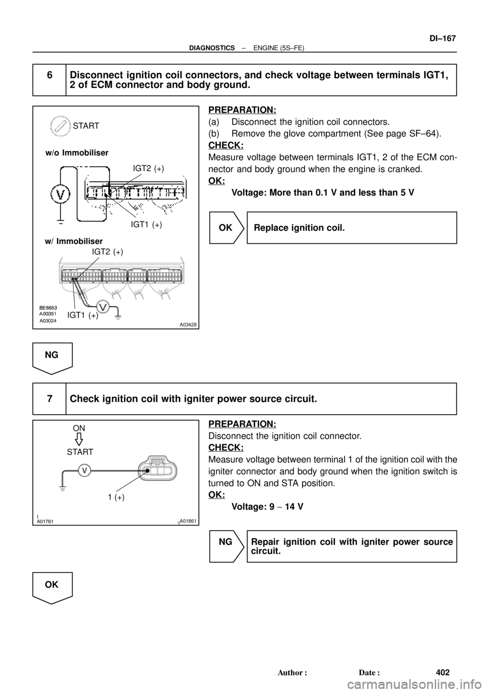
6 Disconnect ignition coil connectors, and check voltage between terminals IGT1,
2 of ECM connector and body ground.
PREPARATION:
(a) Disconnect the ignition coil connectors.
(b) Remove the glove compartment (See page SF±64).
CHECK:
Measure voltage between terminals IGT1, 2 of the ECM con-
nector and body ground when the engine is cranked.
OK:
Voltage: More than 0.1 V and less than 5 V
OK Replace ignition coil.
NG
7 Check ignition coil with igniter power source circuit.
PREPARATION:
Disconnect the ignition coil connector.
CHECK:
Measure voltage between terminal 1 of the ignition coil with the
igniter connector and body ground when the ignition switch is
turned to ON and STA position.
OK:
Voltage: 9 ~ 14 V
NG Repair ignition coil with igniter power source
circuit.
OK