Page 2710 of 4770

525 Author�: Date�:
DTC P0340 Camshaft Position Sensor Circuit
Malfunction
CIRCUIT DESCRIPTION
Camshaft position sensor (G22 signal) consist of a signal plate an")
DI±290
± DIAGNOSTICSENGINE (1MZ±FE)
525 Author�: Date�:
DTC P0340 Camshaft Position Sensor Circuit
Malfunction
CIRCUIT DESCRIPTION
Camshaft position sensor (G22 signal) consist of a signal plate and pickup coil.
The G22 signal plate has one tooth, on its outer circumference and is mounted on the left bank camshafts.
When the camshafts rotate, the protrusion on the signal plate and the air gap on the pickup coil change,
causing fluctuations in the magnetic field and generating an electromotive force in the pickup coil.
The NE signal plate has 34 teeth and is mounted on the crankshaft. The NE signal sensor generates 34
signals for every engine revolution. The ECM detects the standard crankshaft angle based on the G22 signal
and the actual crankshaft angle and the engine speed by the NE signals.
DTC No.DTC Detecting ConditionTrouble Area
P0340
No camshaft position sensor signal to ECM during cranking
(2 trip detection logic)�Open or short in camshaft position sensor circuit
�Camshaft position sensor
P0340No camshaft position sensor signal to ECM with engine speed
600 rpm or more
�Camshaft osition sensor
�Starter
�ECM
WIRING DIAGRAM
Refer to DTC P0335 (Crankshaft Position Sensor ºAº Circuit Malfunction) on page DI±287 .
INSPECTION PROCEDURE
HINT:
Read freeze frame data using TOYOTA hand±held tester or OBD II scan tool. Because freeze frame records
the engine conditions when the malfunction is detected, when troubleshooting it is useful for determining
whether the vehicle was running or stopped, the engine warmed up or not, the air±fuel ratio lean or rich, etc.
at the time of the malfunction.
1 Check resistance of camshaft position sensor (See page IG±1).
Reference INSPECTION USING OSCILLOSCOPE
Refer to DTC P0335 on page DI±287.
NG Replace camshaft position sensor.
OK
DI07V±06
Page 2771 of 4770

S00251
From BatteryIgnition Coil
Spark Plug
IGC1
IGC2
IGC3
GND TA C IGT1
IGT2
IGT3
IGF
To Tachometer ECM G
NE
Camshaft
Position
Sensor
Crankshaft
Position
Sensor
Various
SensorNo.2 Cylinder
No.1 Cylinder
No.4 Cylinder
No.3 Cylinder
No.6 Cylinder
No.5 Cylinder
± DIAGNOSTICSENGINE (1MZ±FE)
DI±351
586 Author�: Date�:
DTC P1300 Igniter Circuit Malfunction
CIRCUIT DESCRIPTION
A DIS (Direct Ignition System) has been adopted. The DIS improves the ignition timing accuracy, reduces
high±voltage loss, and enhances the overall reliability of the ignition system by eliminating the distributor.
The DIS is a 2±cylinder simultaneous ignition system which ignites 2 cylinders simultaneously with one igni-
tion coil. In the 2±cylinder simultaneous ignition system, each of the 2 spark plugs is connected to the end
of the secondary winding. High voltage generated in the secondary winding is applied directly to the spark
plugs. The sparks of the 2 spark plugs pass simultaneously from the center electrode to the ground elec-
trode.
The ECM determines ignition timing and outputs the ignition signals (IGT) for each cylinder. Based on IGT
signals, the igniter controls the primary ignition signals (IGC) for all ignition coils. At the same time, the igniter
also sends an ignition confirmation signal (IGF) as a fail±safe measure to the ECM.
DTC No.DTC Detecting ConditionTrouble Area
P1300
Condition (a) is repeated 3 times consecutively during 6
consecutively IGT signals while engine is running
(a) IGF signal is not input to ECM for 2 or more ignitions�Open or short in IGF or IGT circuit from igniter to ECM
�Igniter
�ECM
DI084±06
Page 2772 of 4770
S05723
J18
Junction
Connector
A
A A A AII3B±R
B±R B±R W±R128 3
1K 1C
Ignition
Switch
76
1K
1BB±R
G
B±R
B±R Y
LIgnition Coil
Spark Plug
No.1
No.2
No.3
11
12
2
2
ED
BR
3 2 1
10
9
7
6
5
4
W±R LG±B
BR±Y
IgniterECM
IGT1
IGT2
IGT3
IGF5 VInstrument
Panel J/B
E1125
E1113
E1112
E1111GR
B±R
5
5
W±R
Engine Room J/B
2L4
AM2
2A1
B
Fusible
Link
Block 1
1
F6
B±GFL
MAIN
Battery
F4
Instrument
Panel J/B
DI±352
± DIAGNOSTICSENGINE (1MZ±FE)
587 Author�: Date�:
WIRING DIAGRAM
INSPECTION PROCEDURE
HINT:
Read freeze frame data using TOYOTA hand±held tester or OBD II scan tool. Because freeze frame records
the engine conditions when the malfunction is detected, when troubleshooting it is useful for determining
whether the vehicle was running or stopped, the engine warmed up or not, the air±fuel ratio lean or rich, etc.
at the time of the malfunction.
1 Check spark plug and spark of misfiring cylinder (See page DI±276).
NG Go to step 4.
OK
Page 2775 of 4770
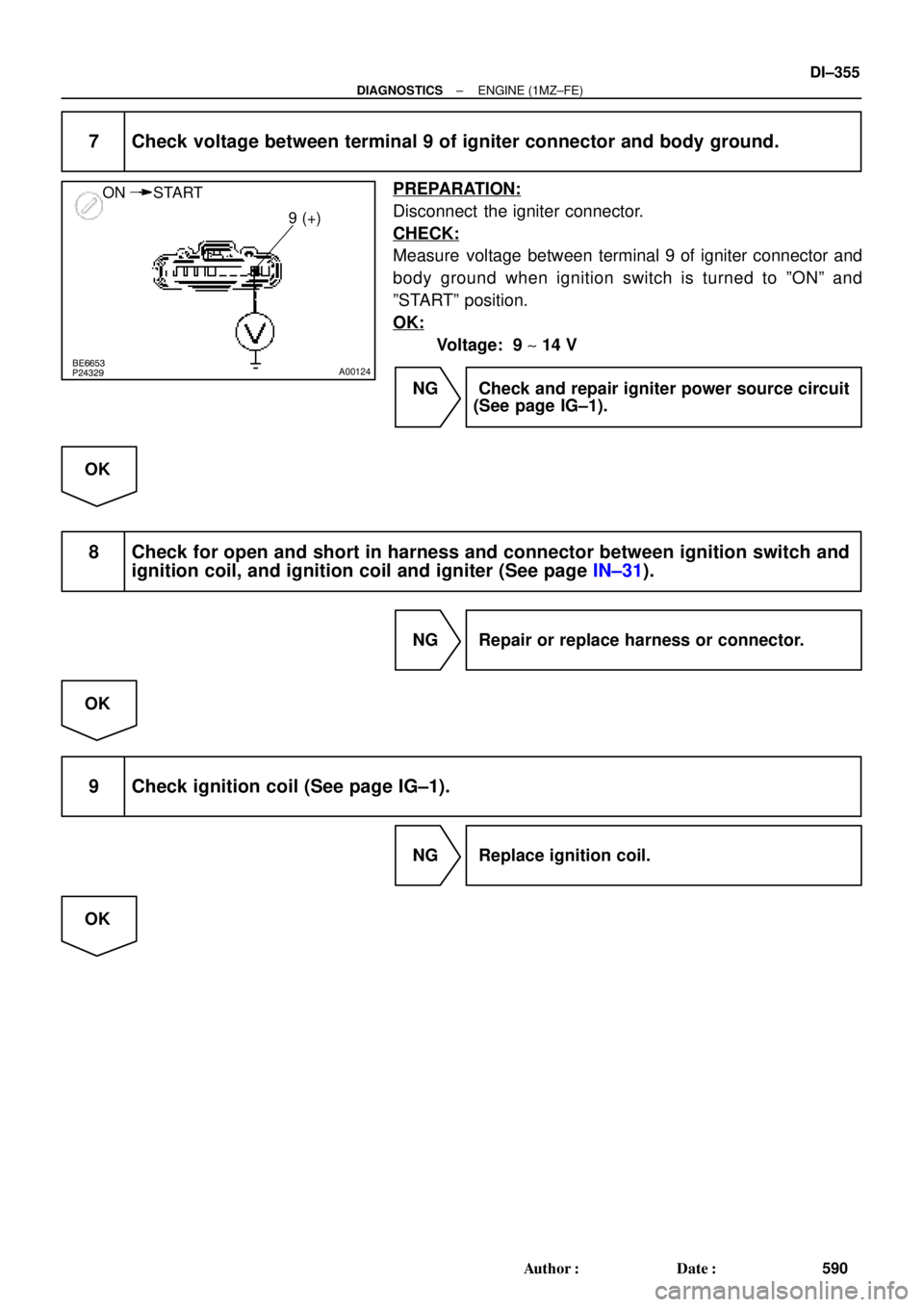
BE6653
P24329A00124
ON START
9 (+)
± DIAGNOSTICSENGINE (1MZ±FE)
DI±355
590 Author�: Date�:
7 Check voltage between terminal 9 of igniter connector and body ground.
PREPARATION:
Disconnect the igniter connector.
CHECK:
Measure voltage between terminal 9 of igniter connector and
body ground when ignition switch is turned to ºONº and
ºSTARTº position.
OK:
Voltage: 9 ~ 14 V
NG Check and repair igniter power source circuit
(See page IG±1).
OK
8 Check for open and short in harness and connector between ignition switch and
ignition coil, and ignition coil and igniter (See page IN±31).
NG Repair or replace harness or connector.
OK
9 Check ignition coil (See page IG±1).
NG Replace ignition coil.
OK
Page 2789 of 4770

A07450
Ignition SwitchW±R B±RInstrument Panel J/B
FL
MAINFusible
Link
Block
BatteryJunction
ConnectorECM
B±R
W±R
BR
BR
W±B
B±Y
B
6
7
2 4
17
2 5
4
1 1B
AA F4 F6 E10E7
2F 2K 2J
2L
2AEFI EFI
RelayEngine Room
J/B+B
E1 17 16
AM2
EB EC
J28
3
1E72
MREL
E78IGSW
J27
1W
1B7
5 IGN
1K3
1K5
B+ B
B±Y
B±W
B±W
J35 J35
C
C
Junction
Connector
B±GJ22
Junction
Connector
± DIAGNOSTICSENGINE (1MZ±FE)
DI±369
604 Author�: Date�:
ECM Power Source Circuit
CIRCUIT INSPECTION
When the ignition switch is turned on, battery positive voltage is applied to terminal IGSW of the ECM and
the EFI main relay (Marking: EFI) control circuit in the ECM sends a signal to terminal MREL of the ECM
switching on the EFI main relay.
This signal causes current to flow to the coil, closing the contacts of the EFI, main relay and supplying power
to terminals +B of the ECM.
If the ignition switch is turned off, the ECM continues to switch on the EFI main relay for a maximum of 2
seconds for the initial setting of the IAC valve.
WIRING DIAGRAM
DI4DU±01
Page 2794 of 4770
A07151
Fuel Pump Circuit Opening Relay
EFI Main Relay
FC
Tr
MREL
IGSW
STA EFI
NEECM
Starter Starter Relay MAIN
Battery AM2IG Switch
(NE Signal) (STA Signal) Park/ Neutral Position Switch IGN
STARTER DI±374
± DIAGNOSTICSENGINE (1MZ±FE)
609 Author�: Date�:
Fuel Pump Control Circuit
CIRCUIT DESCRIPTION
In the diagram below, when the engine is cranked, current flows from terminal ST of the ignition switch to
the starter relay coil and also current flows to terminal STA of ECM (STA signal).
When the STA signal and NE signal are input to the ECM, Tr is turned ON, current flows to coil of the circuit
opening relay, the relay switches on, power is supplied to the fuel pump and the fuel pump operates.
While the NE signal is generated (engine running), the ECM keeps Tr ON (circuit opening relay ON) and the
fuel pump also keeps operating.
DI4DV±01
Page 2815 of 4770

± DIAGNOSTICSAUTOMATIC TRANSAXLE (A140E)
DI±395
630 Author�: Date�:
(c) Replace the ATF.
(1) Remove the drain plug and drain")
Q00061
AT8562
AT3417
OK if hot
Add if hot
AT4252
0 ~ 1 mm (0 ~ 0.04 in.)
± DIAGNOSTICSAUTOMATIC TRANSAXLE (A140E)
DI±395
630 Author�: Date�:
(c) Replace the ATF.
(1) Remove the drain plug and drain the fluid.
(2) Reinstall the drain plug securely.
(3) With the engine OFF add new fluid through the oil
filler pipe.
Fluid type: ATF D±II or DEXRON®III (DEXRON®II)
Capacity: 2.5 liters (2.6 US qts, 2.1 Imp. qts)
(4) Start the engine and shift the shift lever into all posi-
tions from P to L position and then shift into P posi-
tion.
(5) With the engine idling, check the fluid level. Add
fluid up to the COOL level on the dipstick.
(6) Check the fluid level is at the normal operating tem-
perature, 70 ± 80 °C (158 ± 176 °F), and add as
necessary.
NOTICE:
Do not overfill.
(d) Check the fluid leaks.
Check for leaks in the transaxle.
If there are leaks, it is necessary to repair or replace O±rings,
gasket, oil seals, plugs or other parts.
(e) Inspect and adjust the throttle cable.
(1) Check that the accelerator pedal is fully released.
(2) Check that the inner cable is not slack.
(3) Measure the distance between the outer cable end
and stopper on the cable.
Standard distance: 0 ± 1 mm (0 ± 0.04 in.)
If the distance is not standard, adjust the cable by the adjusting
nuts.
Page 2819 of 4770

DI±399
634 Author�: Date�:
7. HYDRAULIC TEST
Measure the line pressure.
NOTICE:
�Do the test at normal operation fluid temperature 50 ± 80 °C (122 ± 176 �")
± DIAGNOSTICSAUTOMATIC TRANSAXLE (A140E)
DI±399
634 Author�: Date�:
7. HYDRAULIC TEST
Measure the line pressure.
NOTICE:
�Do the test at normal operation fluid temperature 50 ± 80 °C (122 ± 176 °F).
�The line pressure test should always be carried out in pairs. One technician should observe
the conditions of wheels or wheel stoppers outside the vehicle while the other is doing the test.
�Be careful to prevent SST's hose from interfering with the exhaust pipe.
(1) Warm up the ATF.
(2) Remove the test plug on the transaxle case front left side and connect SST.
(See page AX±17 for the location to connect SST)
SST 09992±00095 (09992±00231, 09992±00271)
(3) Fully apply the parking brake and chock the 4 wheels.
(4) Connect an OBD II scan tool or TOYOTA hand±held tester to DLC3.
(5) Start the engine and check idling speed.
(6) Keep your left foot pressing firmly on the brake pedal and shift into D position.
(7) Measure the line pressure when the engine is idling.
(8) Depress the accelerator pedal all the way down. Quickly read the highest line pressure when
engine speed reaches stall speed.
(9) In the same manner, do the test in R position.
Specified line pressure:
ConditionD position kPa (kgf/cm2, psi)R position kPa (kgf/cm2, psi)
Idling362 ± 422 (3.7 ± 4.3, 53 ± 61)618 ± 794 (6.3 ± 8.1, 90 ± 115)
Stall735 ± 862 (7.5 ± 8.8, 107 ± 125)1,373 ± 1,608 (14.0 ± 16.4, 199 ± 233)
If the measured pressure is not up to the specified value, recheck the throttle cable adjustment and retest.
Evaluation
ProblemPossible cause
If the measured values at all positions are higher
�Throttle cable out of adjustment
�Throttle valve defective
�Regulator valve defective
If the measured values at all positions are lower
�Throttle cable out of adjustment
�Throttle valve defective
�Regulator valve defective
�Oil pump defective
�O/D direct clutch defective
If pressure is low in the D position only�D position circuit fluid leakage
�Forward clutch defective
If pressure is low in the R position only
�R position circuit fluid leakage
�Direct clutch defective
�1st & reverse brake defective

 (STA Signal) Park/ Neutral Position Switch IGN
STARTER D")