Page 3426 of 4770
(d)
(e)
A07364
ConnectorClamp
EM±34
± ENGINE MECHANICAL (5S±FE)CYLINDER HEAD
1206 Author�: Date�:
(j) California:
Disconnect the A/F sensor connector for the wiring side")
S05548
Wire
Clamp
A01564(c)(d)
(e)
A07364
ConnectorClamp
EM±34
± ENGINE MECHANICAL (5S±FE)CYLINDER HEAD
1206 Author�: Date�:
(j) California:
Disconnect the A/F sensor connector for the wiring side
from the bracket on the LH engine hanger.
(k) Except California:
Disconnect the heated oxygen sensor (bank 1 sensor 1)
connector for the wiring side from the bracket on the LH
engine hanger.
5. REMOVE THROTTLE BODY (See page SF±32)
6. REMOVE IGNITION COILS, NO.2 INTAKE MANIFOLD
STAY AND HIGH±TENSION CORDS ASSEMBLY
(a) Disconnect the 2 ignition coil connectors.
(b) Disconnect the 4 high±tension cords from the 2 clamps
on the cylinder head cover.
(c) Disconnect the 4 high±tension cords from the spark
plugs.
(d) Disconnect the wire clamp from the manifold stay.
(e) TMC Made:
Remove the 2 nuts, 2 bolts, 2 ignition coils, manifold stay
and 4 high±tension cords assembly.
(f) TMMK Made:
Remove the nut, 3 bolts, 2 ignition coils, manifold stay and
4 high±tension cords assembly.
7. DISCONNECT OIL PRESSURE SWITCH CONNECTOR
8. DISCONNECT NOISE FILTER CONNECTOR
9. REMOVE WATER OUTLET
(a) Disconnect the ECT sensor connector.
(b) Disconnect the ECT sender gauge connector.
(c) Disconnect the radiator hose from the water outlet.
(d) Disconnect the water bypass pipe hose from the water
outlet.
(e) Disconnect the heater water hose from the water outlet.
(f) Remove the 2 nuts, water outlet and gasket.
10. REMOVE INTAKE MANIFOLD STAY
Remove the bolt, nut and intake manifold stay.
11. REMOVE EGR VALVE AND VACUUM MODULATOR
(a) Disconnect the VSV connector for the EGR.
(b) Disconnect the hose clamp from the bracket on the intake
manifold.
(c) Remove the bolt, and disconnect the VSV for EGR from
the intake manifold.
Page 3429 of 4770
CYLINDER HEAD
EM±37
1209 Author�: Date�:
NOTICE:
�Support the timing belt, so the meshing of the crank-
shaft timing pulley and")
A02593
S05933
P03355
10 ± 45°
Knock
Pin
± ENGINE MECHANICAL (5S±FE)CYLINDER HEAD
EM±37
1209 Author�: Date�:
NOTICE:
�Support the timing belt, so the meshing of the crank-
shaft timing pulley and timing belt does not shift.
�Be careful not to drop anything inside the timing belt
cover.
�Do not allow the belt to come into contact with oil, wa-
ter or dust.
21. REMOVE ENGINE HANGERS AND GENERATOR
BRACKET
(a) Remove the 3 bolts, the generator bracket and RH engine
hanger assembly.
(b) Remove the bolt and LH engine hanger.
22. REMOVE OIL PRESSURE SWITCH
23. REMOVE CYLINDER HEAD COVER
Remove the 4 nuts, grommets, head cover and gasket.
HINT:
Arrange the grommets in the correct order, so that they can be
reinstalled into their original positions. This minimizes any pos-
sibility of oil leakage due to reuse of the grommets in different
positions.
24. REMOVE CAMSHAFTS
NOTICE:
Since the thrust clearance of the camshaft is small, the
camshaft must be kept level while it is being removed. If the
camshaft is not kept level, the portion of the cylinder head
receiving the shaft thrust may crack or be damaged, caus-
ing the camshaft to seize or break. To avoid this, the follow-
ing steps should be carried out.
(a) Remove the exhaust camshaft.
(1) Set the knock pin of the intake camshaft at 10 ± 45°
BTDC of camshaft angle.
HINT:
The above angle allows No.2 and No.4 cylinder cam lobes of
the exhaust camshaft to push their valve lifters evenly.
Page 3431 of 4770
CYLINDER HEAD
EM±39
1211 Author�: Date�:
(b) Remove the intake camshaft.
(1) Set the knock pin of the intak")
P03358
8 0 ± 11 5°
Knock
Pin
P03359
P03360
1 2
3 45 6
P03361
± ENGINE MECHANICAL (5S±FE)CYLINDER HEAD
EM±39
1211 Author�: Date�:
(b) Remove the intake camshaft.
(1) Set the knock pin of the intake camshaft at 80 ±
11 5° BTDC of camshaft angle.
HINT:
The above angle allows the No.1 and No.3 cylinder cam lobes
of intake camshaft to push their valve lifters evenly.
(2) Remove the 2 bolts, front bearing cap and oil seal.
(3) Uniformly loosen and remove the 6 bolts on the
No.1, No.3 and No.4 bearing caps in several
passes, in the sequence shown.
NOTICE:
Do not remove the No.2 bearing cap bolts at this stage.
(4) Remove the No.1, No.3 and No.4 bearing caps.
(5) Alternately loosen and remove the 2 bolts on the
No.2 bearing cap.
HINT:
�As the 2 No.2 bearing cap bolts are loosened, make sure
that the camshaft is lifted out straight and level, after
breaking adhesion on the front bearing cap.
�If the camshaft is not being lifted out straight and level, re-
tighten the 2 No.2 bearing cap bolts. Reverse the order
of above steps from (5) to (1) and reset the knock pin of
the intake camshaft at 80 ± 115° BTDC, and repeat steps
from (2) to (5) once again.
NOTICE:
Do not pry on or attempt to force the camshaft with a tool
or other object.
(6) Remove the No.2 bearing cap and camshaft.
Page 3433 of 4770
EM089±03
P03265
SST
P03266
± ENGINE MECHANICAL (5S±FE)CYLINDER HEAD
EM±41
1213 Author�: Date�:
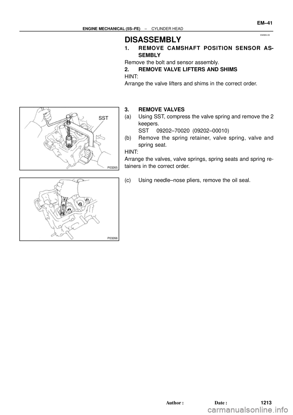
DISASSEMBLY
1. REMOVE CAMSHAFT POSITION SENSOR AS-
SEMBLY
Remove the bolt and sensor assembly.
2. REMOVE VALVE LIFTERS AND SHIMS
HINT:
Arrange the valve lifters and shims in the correct order.
3. REMOVE VALVES
(a) Using SST, compress the valve spring and remove the 2
keepers.
SST 09202±70020 (09202±00010)
(b) Remove the spring retainer, valve spring, valve and
spring seat.
HINT:
Arrange the valves, valve springs, spring seats and spring re-
tainers in the correct order.
(c) Using needle±nose pliers, remove the oil seal.
Page 3434 of 4770
CYLINDER HEAD
1214 Author�: Date�:
INSPECTION
1. CLE AN TO P SURFACE S OF PIS TO NS AND CY L-
INDER BLOCK
(a) Turn the")
EM08A±04
A07356
A07357
P03267
P03268
P03149
EM±42
± ENGINE MECHANICAL (5S±FE)CYLINDER HEAD
1214 Author�: Date�:
INSPECTION
1. CLE AN TO P SURFACE S OF PIS TO NS AND CY L-
INDER BLOCK
(a) Turn the crankshaft, and bring each piston to top dead
center (TDC). Using a gasket scraper, remove all the car-
bon from the piston top surface.
(b) Using a gasket scraper, remove all the gasket material
from the cylinder block surface.
(c) Using compressed air, blow carbon and oil from the bolt
holes.
CAUTION:
Protect your eyes when using high±pressure compressed
air.
2. INSPECT TOP SURFACE OF CYLINDER BLOCK FOR
FLATNESS (See page EM±97)
3. CLEAN CYLINDER HEAD
(a) Using a gasket scraper, remove all the gasket material
from the cylinder block contact surface.
NOTICE:
Be careful not to scratch the cylinder block contact sur-
face.
(b) Using a wire brush, remove all the carbon from the com-
bustion chamber.
NOTICE:
Be careful not to scratch the cylinder block contact sur-
face.
(c) Using a valve guide bushing brush and solvent, clean all
the guide bushings.
Page 3436 of 4770
CYLINDER HEAD
1216 Author�: Date�:
6. INSPECT VALVE STEMS AND GUIDE BUSHINGS
(a) Using a caliper gauge, measure")
Z02754
Z00052
Z00054
44.5°
EM0181
Margin Thickness EM±44
± ENGINE MECHANICAL (5S±FE)CYLINDER HEAD
1216 Author�: Date�:
6. INSPECT VALVE STEMS AND GUIDE BUSHINGS
(a) Using a caliper gauge, measure the inside diameter of the
guide bushing.
Bushing inside diameter:
6.010 ± 6.030 mm (0.2366 ± 0.2374 in.)
(b) Using a micrometer, measure the diameter of the valve
stem.
Valve stem diameter:
Intake5.970 ± 5.985 mm (0.2350 ± 0.2356 in.)
Exhaust5.965 ± 5.980 mm (0.2348 ± 0.2354 in.)
(c) Subtract the valve stem diameter measurement from the
guide bushing inside diameter measurement.
Standard oil clearance:
Intake0.025 ± 0.060 mm (0.0010 ± 0.0024 in.)
Exhaust0.030 ± 0.065 mm (0.0012 ± 0.0026 in.)
Maximum oil clearance:
Intake0.08 mm (0.0031 in.)
Exhaust0.10 mm (0.0039 in.)
If the clearance is greater than maximum, replace the valve and
guide bushing. (See page EM±50)
7. INSPECT AND GRIND VALVES
(a) Grind the valve enough to remove pits and carbon.
(b) Check that the valve is ground to the correct valve face
angle.
Valve face angle: 44.5°
(c) Check the valve head margin thickness.
Standard margin thickness:
0.8 ± 1.2 mm (0.031 ± 0.047 in.)
Minimum margin thickness: 0.5 mm (0.020 in.)
If the margin thickness is less than minimum, replace the valve.
Page 3439 of 4770
CYLINDER HEAD
EM±47
1219 Author�: Date�:
(c) Using a spring tester, measure the tension of the valve
spring at the specif")
EM0281
EM1628
EM2011
EM2538
EM3322
Free Distance
± ENGINE MECHANICAL (5S±FE)CYLINDER HEAD
EM±47
1219 Author�: Date�:
(c) Using a spring tester, measure the tension of the valve
spring at the specified installed length.
Installed tension:
164 ± 189 N (16.7 ± 19.3 kgf, 36.8 ± 42.5 lbf)
at 34.7 mm (1.366 in.)
If the installed tension is not as specified, replace the valve
spring.
10. INSPECT CAMSHAFTS
(a) Inspect the circle runout.
(1) Place the camshaft on V±blocks.
(2) Using a dial indicator, measure the circle runout at
the center journal.
Maximum circle runout: 0.04 mm (0.0016 in.)
If the circle runout is greater than maximum, replace the cam-
shaft.
(b) Using a micrometer, measure the cam lobe height.
Standard cam lobe height:
Intake42.01 ± 42.11 mm (1.6539 ± 1.6579 in.)
Exhaust40.06 ± 40.16 mm (1.5772 ± 1.5811 in.)
Minimum cam lobe height:
Intake41.90 mm (1.6496 in.)
Exhaust39.95 mm (1.5728 in.)
If the cam lobe height is less than minimum, replace the cam-
shaft.
(c) Using a micrometer, measure the journal diameter.
Journal diameter:
26.959 ± 26.975 mm (1.0614 ± 1.0620 in.)
If the journal diameter is not as specified, check the oil clear-
ance.
(d) Using vernier calipers, measure the free distance be-
tween the gear spring ends.
Free distance: 22.5 ± 22.9 mm (0.886 ± 0.902 in.)
If the free distance is not as specified, replace the gear spring.
Page 3440 of 4770
CYLINDER HEAD
1220 Author�: Date�:
(e) Inspect the journal oil clearance.
(1) Clean the bearing caps and camshaft journals.
(")
EM3371
Plastigage
P00259
EM3310
P00263
EM±48
± ENGINE MECHANICAL (5S±FE)CYLINDER HEAD
1220 Author�: Date�:
(e) Inspect the journal oil clearance.
(1) Clean the bearing caps and camshaft journals.
(2) Check that bearings for flaking and scoring.
If the bearings are damaged, replace the bearing caps and cyl-
inder head as a set.
(3) Place the camshafts on the cylinder head.
(4) Lay a strip of Plastigage across each of the cam-
shaft journals.
(5) Install the bearing caps. (See page EM±53)
NOTICE:
Do not turn the camshaft.
(6) Remove the bearing caps.
(7) Measure the Plastigage at its widest point.
Standard oil clearance:
0.025 ± 0.062 mm (0.0010 ± 0.0024 in.)
Maximum oil clearance: 0.10 mm (0.0039 in.)
If the oil clearance is greater than maximum, replace the cam-
shaft. If necessary, replace the bearing caps and cylinder head
as a set.
(8) Completely remove the Plastigage.
(f) Inspect the camshaft thrust clearance.
(1) Install the camshaft. (See page EM±53)
(2) Using a dial indicator, measure the thrust clearance
while moving the camshaft back and forth.
Standard thrust clearance:
Intake0.045 ± 0.100 mm (0.0018 ± 0.0039 in.)
Exhaust0.030 ± 0.085 mm (0.0012 ± 0.0033 in.)
Maximum thrust clearance:
Intake0.12 mm (0.0047 in.)
Exhaust0.10 mm (0.0039 in.)
If the thrust clearance is greater than maximum, replace the
camshaft. If necessary, replace the bearing caps and cylinder
head as a set.