Page 3014 of 4770
F00116
ABS & TRAC ECU
A15
A16 B
G6W
12
R
IK2
IL1 Left Front
Speed SensorRight Front
Speed Sensor
B
G R
Left Rear
Speed Sensor Right Rear
Speed Sensor2
1
1
2
2
1A15
A15
A15
A16
A16
A16 R
IK21
G
W
IL11 2FR+
FL+
FL±
RR+ 17
RL+
RL± 4 18
5FR±
RR± 10
ID19
ID12
1 93ABS & TRAC ECU
A15
A16 B
G6W
12
R
IK2
IL1 Right Front
Speed Sensor
B
W
*1
G R
Left Rear
Speed Sensor2
1
1
2
2
1A15
A15
A15
A16
A16
A16 R
IK21
G
W
IL11 2FR+
FL+
FL±
RR+ 17
RL+
RL± 4 18
5FR±
RR± 10
ID19
ID12
1 93
Y
*2
G*1
BR*2
B*1
Y*2
W*1
P*2
*1
: TMC Made*2: TMMK Made DI±594
± DIAGNOSTICSABS & TRACTION CONTROL SYSTEM
829 Author�: Date�:
WIRING DIAGRAM
Page 3016 of 4770
BR3795
OK NG OK NG
OK NGOK NG
W04200
Normal Signal Waveform
1 V / Division2 m/s / DivisionGND
DI±596
± DIAGNOSTICSABS & TRACTION CONTROL SYSTEM
831 Author�: Date�:
2 Check for open and short circuit in harness and connector between each speed
sensor and ECU (See page IN±31).
NG Repair or replace harness or connector.
OK
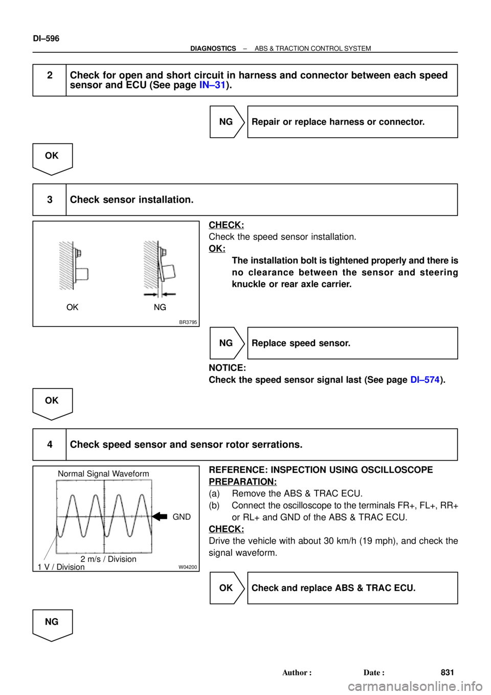
3 Check sensor installation.
CHECK:
Check the speed sensor installation.
OK:
The installation bolt is tightened properly and there is
no clearance between the sensor and steering
knuckle or rear axle carrier.
NG Replace speed sensor.
NOTICE:
Check the speed sensor signal last (See page DI±574).
OK
4 Check speed sensor and sensor rotor serrations.
REFERENCE: INSPECTION USING OSCILLOSCOPE
PREPARATION:
(a) Remove the ABS & TRAC ECU.
(b) Connect the oscilloscope to the terminals FR+, FL+, RR+
or RL+ and GND of the ABS & TRAC ECU.
CHECK:
Drive the vehicle with about 30 km/h (19 mph), and check the
signal waveform.
OK Check and replace ABS & TRAC ECU.
NG
Page 3017 of 4770
R00948
R00947
± DIAGNOSTICSABS & TRACTION CONTROL SYSTEM
DI±597
832 Author�: Date�:
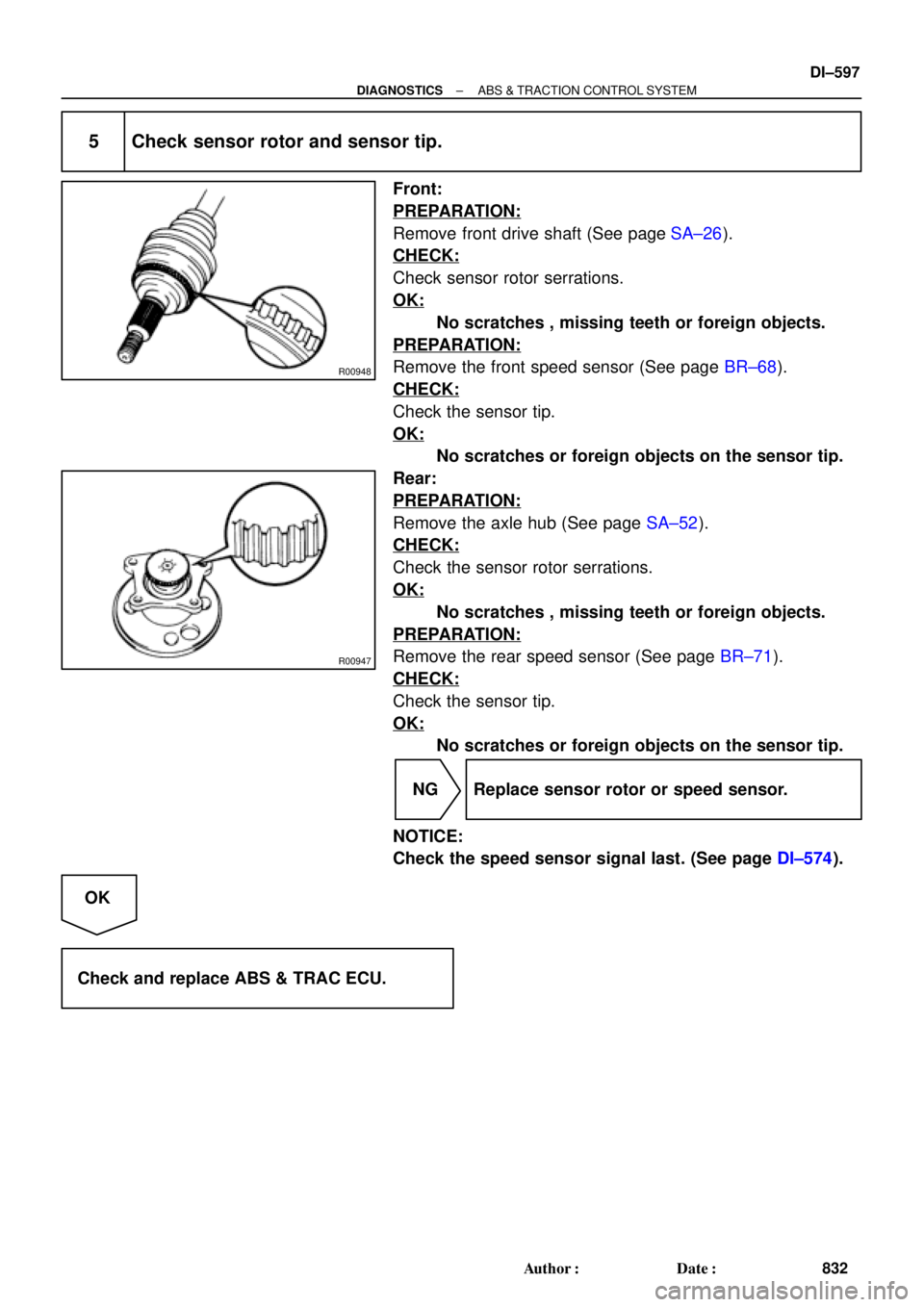
5 Check sensor rotor and sensor tip.
Front:
PREPARATION:
Remove front drive shaft (See page SA±26).
CHECK:
Check sensor rotor serrations.
OK:
No scratches , missing teeth or foreign objects.
PREPARATION:
Remove the front speed sensor (See page BR±68).
CHECK:
Check the sensor tip.
OK:
No scratches or foreign objects on the sensor tip.
Rear:
PREPARATION:
Remove the axle hub (See page SA±52).
CHECK:
Check the sensor rotor serrations.
OK:
No scratches , missing teeth or foreign objects.
PREPARATION:
Remove the rear speed sensor (See page BR±71).
CHECK:
Check the sensor tip.
OK:
No scratches or foreign objects on the sensor tip.
NG Replace sensor rotor or speed sensor.
NOTICE:
Check the speed sensor signal last. (See page DI±574).
OK
Check and replace ABS & TRAC ECU.
Page 3018 of 4770

F00175
Battery MAIN FL Block
B±G 1K2Ignition
Switch
Instrument Panel J/B
1B
F4 F91A16
GND3
B±R
1Instrument Panel J/B
1
A15 B±YJ/C
4B±R
CABS & TRAC ECU
9
A17 1JJ12
IG1
W±B W
GND1
GND2 21K1
CB±R
A17 W±B
W±B
EA8
15
109
W±B
W±B
Battery MAIN FL Block
B±G 1K2Ignition
Switch
Instrument Panel J/B
1B
F4 F91A16
GND3
B±R
1Instrument Panel J/B
1
A15 B±YJ/C
4B±R
CABS & TRAC ECU
9
A17 1JJ12
IG1
W±B W
GND1
GND2 21K1
CB±R
A17 W±B
W±B
EA8
15
109
W±B
W±B
Battery MAIN FL Block
B±G 1K2Ignition
Switch
Instrument Panel J/B
1B
F4 F91A16
GND3
B±R
1Instrument Panel J/B
1
A15 B±YJ/C
4B±R
CABS & TRAC ECU
9
A17 1JJ12
IG1
W±B W
GND1
GND2 21K1
CB±R
A17 W±B
W±B
EA8
15
109
W±B
W±B
Battery MAIN FL Block
B±G 1K2Ignition
Switch
Instrument Panel J/B
1B
F4 F91A16
GND3
B±R
1Instrument Panel J/B
1
A15 B±YJ/C
4B±R
CABS & TRAC ECU
9
A17 1JJ12
IG1
W±B W
GND1
GND2 21K1
CB±R
A17 W±B
W±B
EA8
15
109
W±B
W±BBattery MAIN FL Block
ALT
B±GAM1 1K2Ignition
Switch
Instrument Panel J/B
1B
F4 F91A16
GND3
B±R
1Instrument Panel J/B
1
A15 B±YJ/C
ECU±IG 4B±R
CABS & TRAC ECU
9
A17 1JJ12
IG1
W±B W
GND1
GND2 21K1
CB±R
A17 W±B
W±B
EA8
15
109
W±B
W±B DI±598
± DIAGNOSTICSABS & TRACTION CONTROL SYSTEM
833 Author�: Date�:
DTC 41 IG Power Source Circuit
CIRCUIT DESCRIPTION
This is the power source for the ECU, hence the actuators.
DTC No.DTC Detecting ConditionTrouble Area
41
Detection of any conditions from 1. through 3.:
1. Vehicle speed is 3 km/h (1.9 mph) or more and battery
voltage is less than 9.5 V continues for 10 sec. or more.
2. Battery voltage has never exceeded more than 17.0 V
and has become less than 9.5 V within 2.16 sec., under
malfunction of solenoid relay monitor after the solenoid
relay is ON, at ECU AST terminal voltage of ECU has
become 8.0 V or more or under malfunction of motor
relay monitor and after the motor relay is ON, motor
relay monitor has become ON.
3. Battery voltage is more than 17.0 V , which continues for
1.2 sec. or more or battery voltage has become more
than 17.0 V within 2.16 sec. and solenoid or motor relay
monitor is under malfunction condition.
�Battery
�Charging system
�Power source circuit
�ECU
Fail safe function:
If any trouble occurs in the power source circuit, the ECU cuts off current to the ABS & TRAC solenoid relay
and prohibits ABS control and TRAC control.
WIRING DIAGRAM
DI04N±04
Page 3019 of 4770
F00073
ECU±IGECU±IG
Instrument
Panel J/BECU±IG
± DIAGNOSTICSABS & TRACTION CONTROL SYSTEM
DI±599
834 Author�: Date�:
INSPECTION PROCEDURE
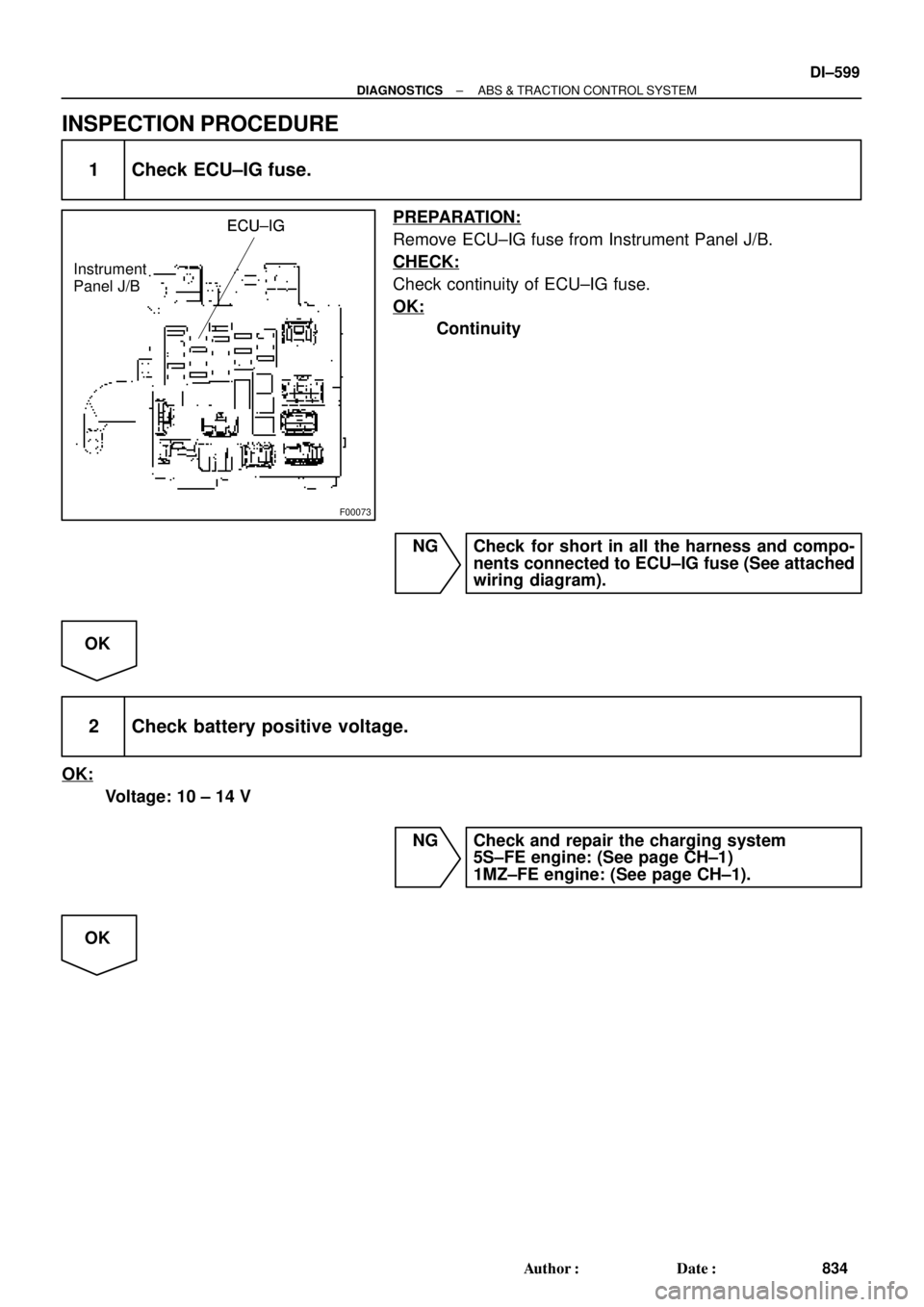
1 Check ECU±IG fuse.
PREPARATION:
Remove ECU±IG fuse from Instrument Panel J/B.
CHECK:
Check continuity of ECU±IG fuse.
OK:
Continuity
NG Check for short in all the harness and compo-
nents connected to ECU±IG fuse (See attached
wiring diagram).
OK
2 Check battery positive voltage.
OK:
Voltage: 10 ± 14 V
NG Check and repair the charging system
5S±FE engine: (See page CH±1)
1MZ±FE engine: (See page CH±1).
OK
Page 3020 of 4770
F00058
IG1
GND ON
(+)
(±)IG1
GND ON
(+)
(±)IG1
GND ON
(+)
(±)IG1
GND ON
(+)
(±)
F07003
(+)(±) LOCK
GND
DI±600
± DIAGNOSTICSABS & TRACTION CONTROL SYSTEM
835 Author�: Date�:
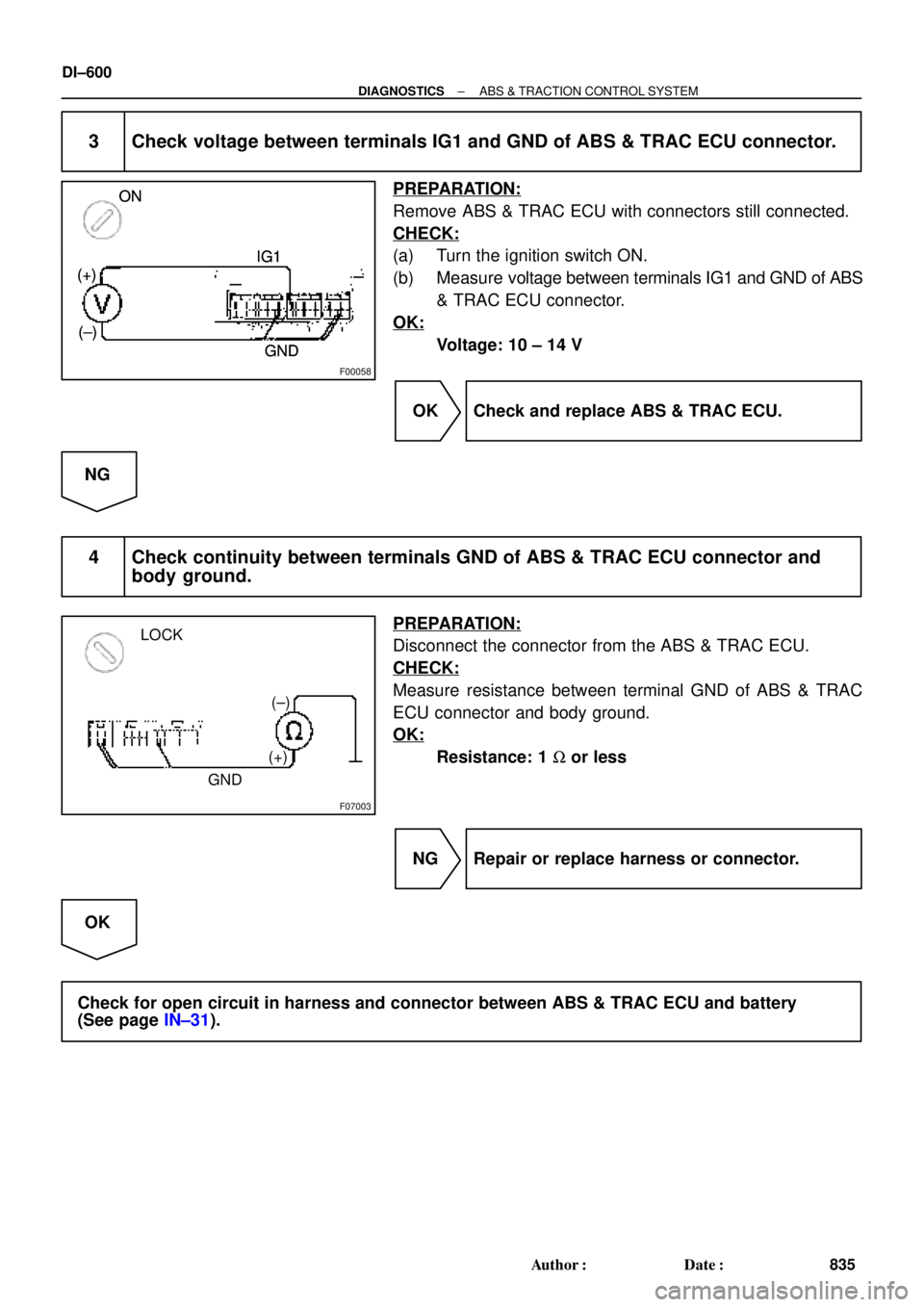
3 Check voltage between terminals IG1 and GND of ABS & TRAC ECU connector.
PREPARATION:
Remove ABS & TRAC ECU with connectors still connected.
CHECK:
(a) Turn the ignition switch ON.
(b) Measure voltage between terminals IG1 and GND of ABS
& TRAC ECU connector.
OK:
Voltage: 10 ± 14 V
OK Check and replace ABS & TRAC ECU.
NG
4 Check continuity between terminals GND of ABS & TRAC ECU connector and
body ground.
PREPARATION:
Disconnect the connector from the ABS & TRAC ECU.
CHECK:
Measure resistance between terminal GND of ABS & TRAC
ECU connector and body ground.
OK:
Resistance: 1 W or less
NG Repair or replace harness or connector.
OK
Check for open circuit in harness and connector between ABS & TRAC ECU and battery
(See page IN±31).
Page 3021 of 4770

± DIAGNOSTICSABS & TRACTION CONTROL SYSTEM
DI±601
836 Author�: Date�:
DTC 43 ABS Control System Malfunction
CIRCUIT DESCRIPTION
DTC No.DTC Detecting ConditionTrouble Area
43
Detection of any conditions from 1. through 8.:
1. During TRAC is in non±operation and DTC of ABS is
output, but TRAC is not during initial lamp checking,
terminal WA of ECU is ON and engine speed is 500 rpm
or more , which continues for 1 sec. or more.
2. Solenoid relay circuit is open or short.
3. Motor relay circuit is open or short.
4. ABS solenoid circuit is open or short.
5. TRAC solenoid circuit is open or short.
6. Speed sensor is under malfunction condition.
7. IG power source is down or raised.
8. Pump motor is locked.
�ABS control system
INSPECTION PROCEDURE
1 Check the DTC for the ABS (See page DI±574).
*1 Repair ABS control system according to the
code output.
*2
Check for ECU connected to malfunction indicator lamp.
*1: Output NG code
*2: Malfunction indicator lamp remains ON.
DI04O±04
Page 3022 of 4770

F00062
ECMABS & TRAC ECU
NEONEO
E8
A16BR±W15 ECMABS & TRAC ECU
NEONEOA16BR±W15 ECMABS & TRAC ECU
NEONEOA16BR±W15 ECMABS & TRAC ECU
NEONEOA16BR±W15
ECMABS & TRAC ECU
NEONEO
A16BR±W15
16
DI±602
± DIAGNOSTICSABS & TRACTION CONTROL SYSTEM
837 Author�: Date�:
DTC 44 NE Signal Circuit
CIRCUIT DESCRIPTION
The ABS & TRAC ECU receives engine speed signals (NE signals) from the ECM.
DTC No.DTC Detecting ConditionTrouble Area
44
Condition 1. or 2. is detected:
1. TRAC is in operation and engine speed is 0 rpm contin-
ues for 2.4 sec. or more.
2. TRAC is in non±operation, sift lever is not in P or N posi-
tion, both the front right and left wheels' speed is 30
km/h (19 mph) or more, engine speed is 0 rpm and does
not have communication malfunction, and malfunction
information of engine system is OFF.
�NEO circuit
�ECM
�ECU
WIRING DIAGRAM
INSPECTION PROCEDURE
1 Check for open and short circuit in harness and connector between terminal
NEO of ABS & TRAC ECU and terminal NEO of ECM (See page IN±31).
NG Repair or replace harness or connector.
OK
DI04P±04