Page 2995 of 4770
H07517
TOYOTA
Hand±held Tester
DLC2
BR3890
N09348
Hand±held Tester
Break±out±boxECUTOYOTA
TOYOTA
± DIAGNOSTICSABS & TRACTION CONTROL SYSTEM
DI±575
810 Author�: Date�:
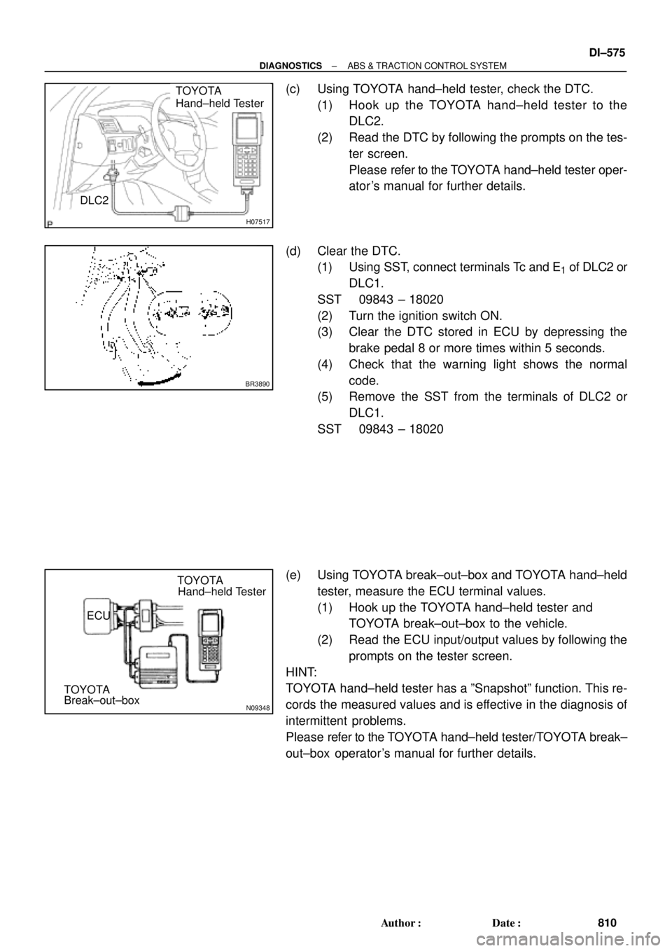
(c) Using TOYOTA hand±held tester, check the DTC.
(1) Hook up the TOYOTA hand±held tester to the
DLC2.
(2) Read the DTC by following the prompts on the tes-
ter screen.
Please refer to the TOYOTA hand±held tester oper-
ator 's manual for further details.
(d) Clear the DTC.
(1) Using SST, connect terminals Tc and E
1 of DLC2 or
DLC1.
SST 09843 ± 18020
(2) Turn the ignition switch ON.
(3) Clear the DTC stored in ECU by depressing the
brake pedal 8 or more times within 5 seconds.
(4) Check that the warning light shows the normal
code.
(5) Remove the SST from the terminals of DLC2 or
DLC1.
SST 09843 ± 18020
(e) Using TOYOTA break±out±box and TOYOTA hand±held
tester, measure the ECU terminal values.
(1) Hook up the TOYOTA hand±held tester and
TOYOTA break±out±box to the vehicle.
(2) Read the ECU input/output values by following the
prompts on the tester screen.
HINT:
TOYOTA hand±held tester has a ºSnapshotº function. This re-
cords the measured values and is effective in the diagnosis of
intermittent problems.
Please refer to the TOYOTA hand±held tester/TOYOTA break±
out±box operator's manual for further details.
Page 2998 of 4770
DI04F±04
DI±578
± DIAGNOSTICSABS & TRACTION CONTROL SYSTEM
813 Author�: Date�:
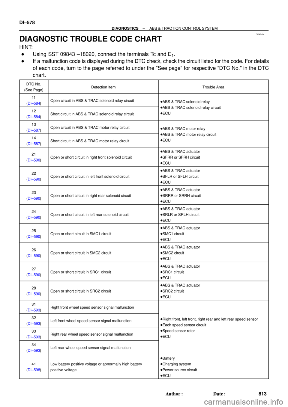
DIAGNOSTIC TROUBLE CODE CHART
HINT:
�Using SST 09843 ±18020, connect the terminals Tc and E1.
�If a malfunction code is displayed during the DTC check, check the circuit listed for the code. For details
of each code, turn to the page referred to under the ºSee pageº for respective ºDTC No.º in the DTC
chart.
DTC No.
(See Page)Detection ItemTrouble Area
11
(DI±584)Open circuit in ABS & TRAC solenoid relay circuit�ABS & TRAC solenoid relay
ABS & TRAC l id l i it12
(DI±584)Short circuit in ABS & TRAC solenoid relay circuit
�ABS & TRAC solenoid relay circuit
�ECU
13
(DI±587)Open circuit in ABS & TRAC motor relay circuit�ABS & TRAC motor relay
ABS & TRAC t l i it14
(DI±587)Short circuit in ABS & TRAC motor relay circuit
�ABS & TRAC motor relay circuit
�ECU
21
(DI±590)Open or short circuit in right front solenoid circuit
�ABS & TRAC actuator
�SFRR or SFRH circuit
�ECU
22
(DI±590)Open or short circuit in left front solenoid circuit
�ABS & TRAC actuator
�SFLR or SFLH circuit
�ECU
23
(DI±590)Open or short circuit in right rear solenoid circuit
�ABS & TRAC actuator
�SRRR or SRRH circuit
�ECU
24
(DI±590)Open or short circuit in left rear solenoid circuit
�ABS & TRAC actuator
�SRLR or SRLH circuit
�ECU
25
(DI±590)Open or short circuit in SMC1 circuit
�ABS & TRAC actuator
�SMC1 circuit
�ECU
26
(DI±590)Open or short circuit in SMC2 circuit
�ABS & TRAC actuator
�SMC2 circuit
�ECU
27
(DI±590)Open or short circuit in SRC1 circuit
�ABS & TRAC actuator
�SRC1 circuit
�ECU
28
(DI±590)Open or short circuit in SRC2 circuit
�ABS & TRAC actuator
�SRC2 circuit
�ECU
31
(DI±593)Right front wheel speed sensor signal malfunction
32
(DI±593)Left front wheel speed sensor signal malfunction�Right front, left front, right rear and left rear speed sensor
�Each speed sensor circuit
33
(DI±593)Right rear wheel speed sensor signal malfunction
�Each s eed sensor circuit
�Speed sensor rotor
�ECU
34
(DI±593)Left rear wheel speed sensor signal malfunction
41
(DI±598)Low battery positive voltage or abnormally high battery
positive voltage
�Battery
�Charging system
�Power source circuit
�ECU
Page 2999 of 4770
± DIAGNOSTICSABS & TRACTION CONTROL SYSTEM
DI±579
814 Author�: Date�:
43*
(DI±601)Malfunction in ABS control system�ABS control system
44*
(DI±602)Open or short circuit in NE signal circuit
�NEO circuit
�ECM
�ECU
49
(DI±604)Open circuit in stop light switch circuit
�Stop light switch
�Stop light switch circuit
�ECU
51
(DI±606)Pump motor is locked�ABS pump motor
53*
(DI±608)Malfunction in ECM communication circuit
�TRC+ or TRC ± circuit
�EFI+ or EFI± circuit
�ECM
�ECU
61*
(DI±609)Malfunction in engine control system�Engine control system
Always ON
(DI±610)Malfunction in ECU�ECU
*: TRAC OFF indicator light blinking
Page 3000 of 4770
DI04G±04
F01177
SLIP Indicator Light
TRAC OFF Indicator Light
ABS Warning Light
DLC1
DLC2
Rear Speed Sensor
Sensor Rotor ABS & TRAC ActuatorABS & TRAC ECU
TRAC OFF Switch
ABS & TRAC
Solenoid Relay
ABS & TRAC
Motor RelaySensor Rotor
Front Speed Sensor
Stop Light Switch Front Speed Sensor
DI±580
± DIAGNOSTICSABS & TRACTION CONTROL SYSTEM
815 Author�: Date�:
PARTS LOCATION
Page 3001 of 4770
DI1JO±03
R05698
A15 A16A17
1 2 3 4 5 6 7 8 9 10
21 11 12 13
14
15 16 17 18 19
20 22 23 24 25 261 2 3 4 5
4 6 7
8
9 10 11 12 13 14 16 151
2 3 5 6
7 8
9 10 11 12
± DIAGNOSTICSABS & TRACTION CONTROL SYSTEM
DI±581
816 Author�: Date�:
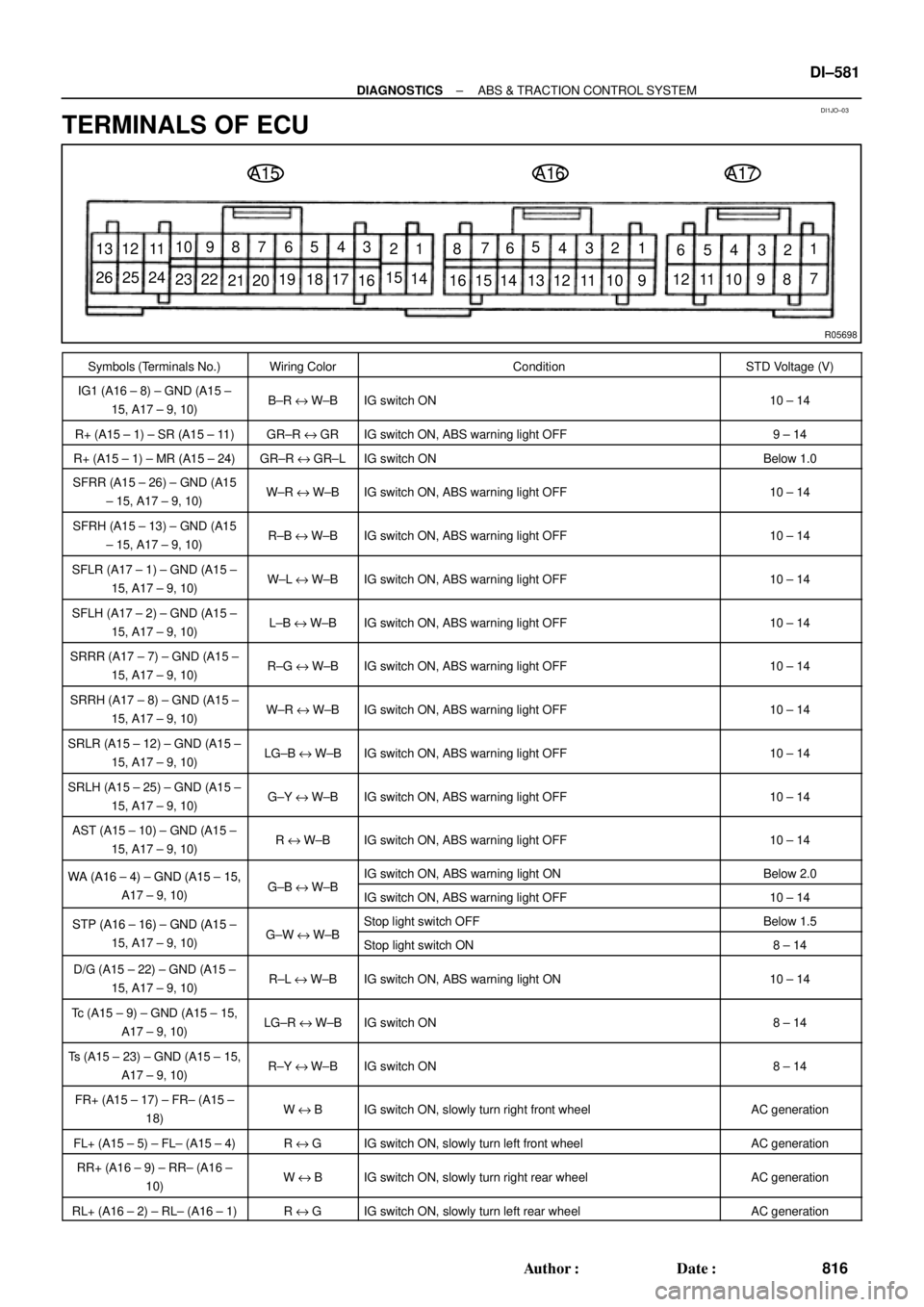
TERMINALS OF ECU
Symbols (Terminals No.)Wiring ColorConditionSTD Voltage (V)
IG1 (A16 ± 8) ± GND (A15 ±
15, A17 ± 9, 10)B±R e W±BIG switch ON10 ± 14
R+ (A15 ± 1) ± SR (A15 ± 11)GR±R e GRIG switch ON, ABS warning light OFF9 ± 14
R+ (A15 ± 1) ± MR (A15 ± 24)GR±R e GR±LIG switch ONBelow 1.0
SFRR (A15 ± 26) ± GND (A15
± 15, A17 ± 9, 10)W±R e W±BIG switch ON, ABS warning light OFF10 ± 14
SFRH (A15 ± 13) ± GND (A15
± 15, A17 ± 9, 10)R±B e W±BIG switch ON, ABS warning light OFF10 ± 14
SFLR (A17 ± 1) ± GND (A15 ±
15, A17 ± 9, 10)W±L e W±BIG switch ON, ABS warning light OFF10 ± 14
SFLH (A17 ± 2) ± GND (A15 ±
15, A17 ± 9, 10)L±B e W±BIG switch ON, ABS warning light OFF10 ± 14
SRRR (A17 ± 7) ± GND (A15 ±
15, A17 ± 9, 10)R±G e W±BIG switch ON, ABS warning light OFF10 ± 14
SRRH (A17 ± 8) ± GND (A15 ±
15, A17 ± 9, 10)W±R e W±BIG switch ON, ABS warning light OFF10 ± 14
SRLR (A15 ± 12) ± GND (A15 ±
15, A17 ± 9, 10)LG±B e W±BIG switch ON, ABS warning light OFF10 ± 14
SRLH (A15 ± 25) ± GND (A15 ±
15, A17 ± 9, 10)G±Y e W±BIG switch ON, ABS warning light OFF10 ± 14
AST (A15 ± 10) ± GND (A15 ±
15, A17 ± 9, 10)R e W±BIG switch ON, ABS warning light OFF10 ± 14
WA (A16 ± 4) ± GND (A15 ± 15,GBWBIG switch ON, ABS warning light ONBelow 2.0WA (A16 4) GND (A15 15,
A17 ± 9, 10)G±B e W±BIG switch ON, ABS warning light OFF10 ± 14
STP (A16 ± 16) ± GND (A15 ±GWWBStop light switch OFFBelow 1.5STP (A16 16) GND (A15
15, A17 ± 9, 10)G±W e W±BStop light switch ON8 ± 14
D/G (A15 ± 22) ± GND (A15 ±
15, A17 ± 9, 10)R±L e W±BIG switch ON, ABS warning light ON10 ± 14
Tc (A15 ± 9) ± GND (A15 ± 15,
A17 ± 9, 10)LG±R e W±BIG switch ON8 ± 14
Ts (A15 ± 23) ± GND (A15 ± 15,
A17 ± 9, 10)R±Y eW±BIG switch ON8 ± 14
FR+ (A15 ± 17) ± FR± (A15 ±
18)W e BIG switch ON, slowly turn right front wheelAC generation
FL+ (A15 ± 5) ± FL± (A15 ± 4)R e GIG switch ON, slowly turn left front wheelAC generation
RR+ (A16 ± 9) ± RR± (A16 ±
10)W e BIG switch ON, slowly turn right rear wheelAC generation
RL+ (A16 ± 2) ± RL± (A16 ± 1)R e GIG switch ON, slowly turn left rear wheelAC generation
Page 3003 of 4770
DI04I±04
± DIAGNOSTICSABS & TRACTION CONTROL SYSTEM
DI±583
818 Author�: Date�:
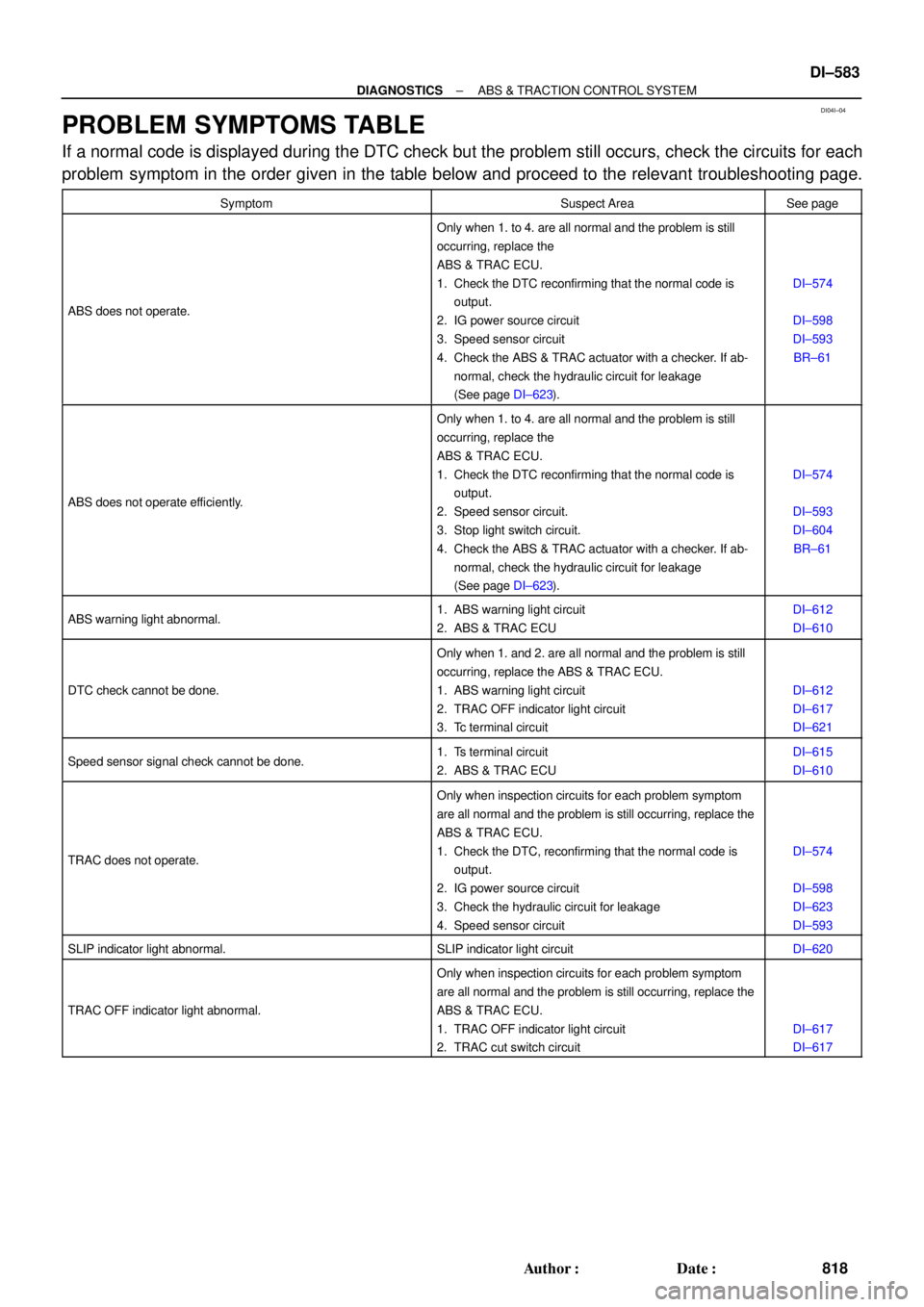
PROBLEM SYMPTOMS TABLE
If a normal code is displayed during the DTC check but the problem still occurs, check the circuits for each
problem symptom in the order given in the table below and proceed to the relevant troubleshooting page.
SymptomSuspect AreaSee page
ABS does not operate.
Only when 1. to 4. are all normal and the problem is still
occurring, replace the
ABS & TRAC ECU.
1. Check the DTC reconfirming that the normal code is
output.
2. IG power source circuit
3. Speed sensor circuit
4. Check the ABS & TRAC actuator with a checker. If ab-
normal, check the hydraulic circuit for leakage
(See page DI±623).
DI±574
DI±598
DI±593
BR±61
ABS does not operate efficiently.
Only when 1. to 4. are all normal and the problem is still
occurring, replace the
ABS & TRAC ECU.
1. Check the DTC reconfirming that the normal code is
output.
2. Speed sensor circuit.
3. Stop light switch circuit.
4. Check the ABS & TRAC actuator with a checker. If ab-
normal, check the hydraulic circuit for leakage
(See page DI±623).
DI±574
DI±593
DI±604
BR±61
ABS warning light abnormal.1. ABS warning light circuit
2. ABS & TRAC ECUDI±612
DI±610
DTC check cannot be done.
Only when 1. and 2. are all normal and the problem is still
occurring, replace the ABS & TRAC ECU.
1. ABS warning light circuit
2. TRAC OFF indicator light circuit
3. Tc terminal circuit
DI±612
DI±617
DI±621
Speed sensor signal check cannot be done.1. Ts terminal circuit
2. ABS & TRAC ECUDI±615
DI±610
TRAC does not operate.
Only when inspection circuits for each problem symptom
are all normal and the problem is still occurring, replace the
ABS & TRAC ECU.
1. Check the DTC, reconfirming that the normal code is
output.
2. IG power source circuit
3. Check the hydraulic circuit for leakage
4. Speed sensor circuit
DI±574
DI±598
DI±623
DI±593
SLIP indicator light abnormal.SLIP indicator light circuitDI±620
TRAC OFF indicator light abnormal.
Only when inspection circuits for each problem symptom
are all normal and the problem is still occurring, replace the
ABS & TRAC ECU.
1. TRAC OFF indicator light circuit
2. TRAC cut switch circuit
DI±617
DI±617
Page 3004 of 4770
DI04J±04
F03951
ABS & TRAC Solenoid Relay
Battery
MAINB±G1F4 ALT1F5 B±G
FL
BlockW±B
EA 3 ABS
12
3 Engine Room R/B No. 3
1
2
336
4
53
3
3
W±L
A8
4ABS & TRAC
Actuator
ABS & TRAC
ECU
5
A8R
A1510
AST GR
GR±RABS & TRAC
ECU
11
A15
1
A15SR
R+
DLC1 DI±584
± DIAGNOSTICSABS & TRACTION CONTROL SYSTEM
819 Author�: Date�:
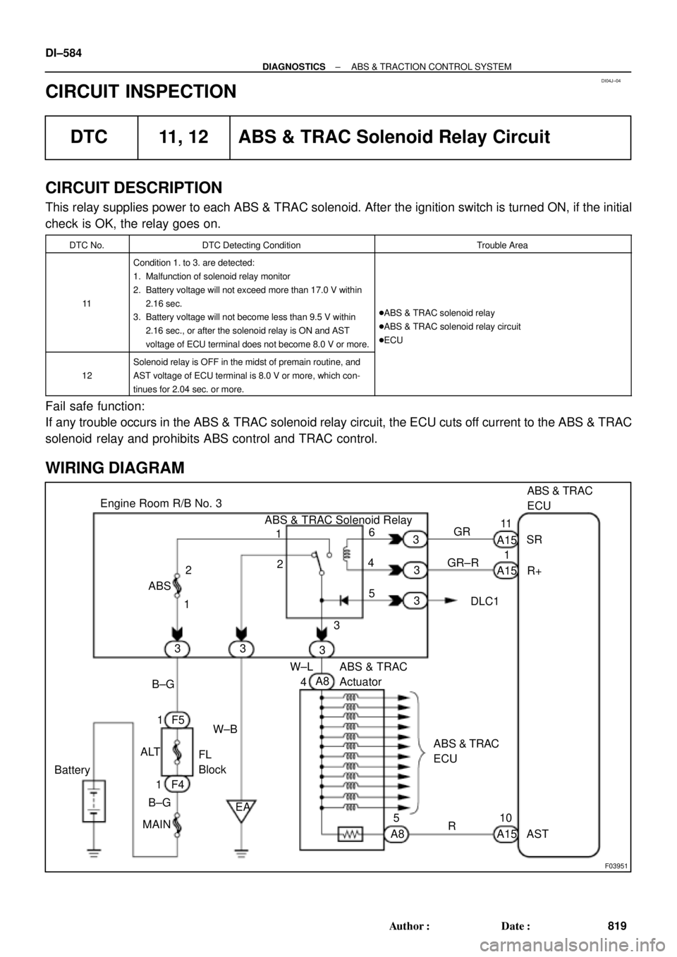
CIRCUIT INSPECTION
DTC 11, 12 ABS & TRAC Solenoid Relay Circuit
CIRCUIT DESCRIPTION
This relay supplies power to each ABS & TRAC solenoid. After the ignition switch is turned ON, if the initial
check is OK, the relay goes on.
DTC No.DTC Detecting ConditionTrouble Area
11
Condition 1. to 3. are detected:
1. Malfunction of solenoid relay monitor
2. Battery voltage will not exceed more than 17.0 V within
2.16 sec.
3. Battery voltage will not become less than 9.5 V within
2.16 sec., or after the solenoid relay is ON and AST
voltage of ECU terminal does not become 8.0 V or more.
�ABS & TRAC solenoid relay
�ABS & TRAC solenoid relay circuit
�ECU
12
Solenoid relay is OFF in the midst of premain routine, and
AST voltage of ECU terminal is 8.0 V or more, which con-
tinues for 2.04 sec. or more.
Fail safe function:
If any trouble occurs in the ABS & TRAC solenoid relay circuit, the ECU cuts off current to the ABS & TRAC
solenoid relay and prohibits ABS control and TRAC control.
WIRING DIAGRAM
Page 3005 of 4770
F00182
(+)(±)
(+)(±)
(+)(±)(+)(±)
123
456
Engine Room R/B No. 3
F00055
ABS & TRAC
Solenoid
Relay
A15
AST
4
5
ABS & TRAC
Actuator
ECU
ABS & TRAC
Solenoid
Relay
A15
AST
4
5
ABS & TRAC
Actuator
ECU
ABS & TRAC
Solenoid
Relay
A15
AST
4
5
ABS & TRAC
Actuator
ECU
ABS & TRAC
Solenoid
Relay3
A8
A8
A15
AST
4
5
ABS & TRAC
Actuator
ECUEngine Room R/B No. 3
± DIAGNOSTICSABS & TRACTION CONTROL SYSTEM
DI±585
820 Author�: Date�:
INSPECTION PROCEDURE
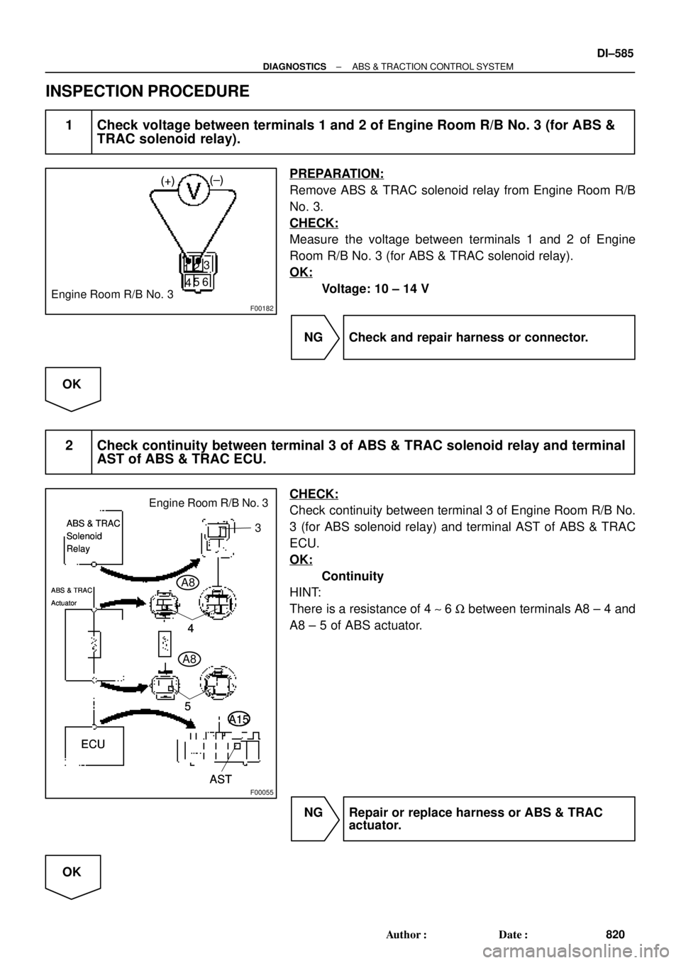
1 Check voltage between terminals 1 and 2 of Engine Room R/B No. 3 (for ABS &
TRAC solenoid relay).
PREPARATION:
Remove ABS & TRAC solenoid relay from Engine Room R/B
No. 3.
CHECK:
Measure the voltage between terminals 1 and 2 of Engine
Room R/B No. 3 (for ABS & TRAC solenoid relay).
OK:
Voltage: 10 ± 14 V
NG Check and repair harness or connector.
OK
2 Check continuity between terminal 3 of ABS & TRAC solenoid relay and terminal
AST of ABS & TRAC ECU.
CHECK:
Check continuity between terminal 3 of Engine Room R/B No.
3 (for ABS solenoid relay) and terminal AST of ABS & TRAC
ECU.
OK:
Continuity
HINT:
There is a resistance of 4 ~ 6 W between terminals A8 ± 4 and
A8 ± 5 of ABS actuator.
NG Repair or replace harness or ABS & TRAC
actuator.
OK