Page 2966 of 4770

DI040±08
F03949
Actuator Assembly
BatteryActuator Assembly
MAINB±GF4 1 ALT
FL
Block 1F5 B±G3
ABS
12 3
Engine
Room R/B
No.3L
L
18
A6
+B+BA6
Valve Relay
Motor Relay17
A6 16 GND2
W±BEA
W±B
W±B 19
A6GND1 ECU DI±546
± DIAGNOSTICSANTI±LOCK BRAKE SYSTEM (BOSCH Made)
781 Author�: Date�:
CIRCUIT INSPECTION
DTC 11 ABS Solenoid Valve Relay Circuit
CIRCUIT DESCRIPTION
This relay supplies power to each ABS solenoid. After the ignition switch is turned ON, if the initial check is
OK, the relay goes on.
DTC No.DTC Detecting ConditionTrouble Area
11
Detection of any conditions from 1. through 3.:
1. 3 or more solenoid valves are shown faulty in response
and simultaneously valve supply voltage is detected
faulty.
2. Solenoid valve relay will not be switched OFF.
3. Valve relay is frozen in spite of its high valve relay sup-
ply voltage.
�ABS solenoid valve relay
�Valve supply voltage
�ECU
Fail safe function:
If trouble occurs in the ABS solenoid valve relay circuit, the ECU cuts off current to the ABS solenoid valve
relay and prohibits ABS control.
WIRING DIAGRAM
Page 2967 of 4770
F00064
LOCK
191817
16
(+) (±) LOCK
191817
16
(+) (±)
A6 LOCK
191817
16
(+) (±)
± DIAGNOSTICSANTI±LOCK BRAKE SYSTEM (BOSCH Made)
DI±547
782 Author�: Date�:
INSPECTION PROCEDURE
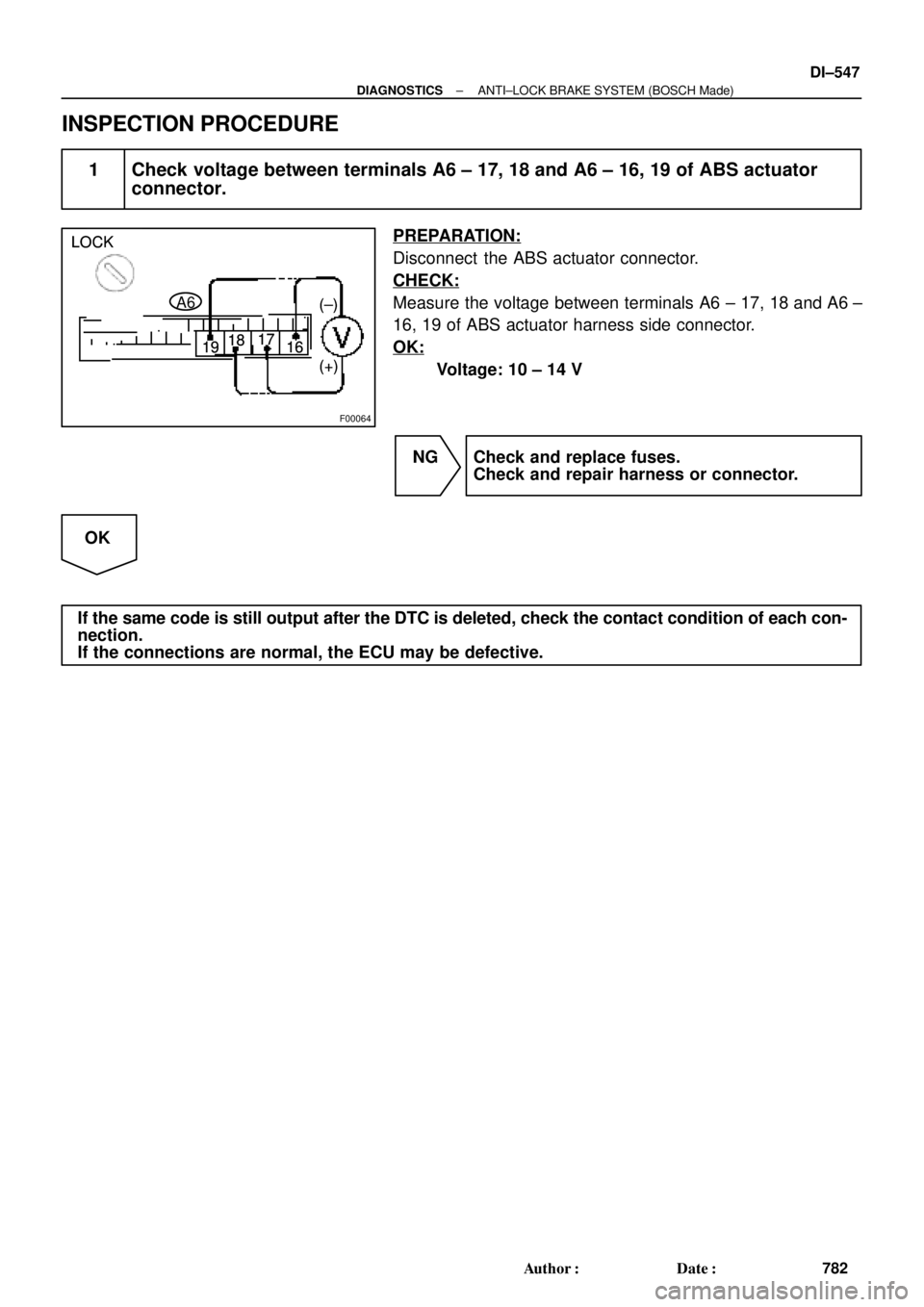
1 Check voltage between terminals A6 ± 17, 18 and A6 ± 16, 19 of ABS actuator
connector.
PREPARATION:
Disconnect the ABS actuator connector.
CHECK:
Measure the voltage between terminals A6 ± 17, 18 and A6 ±
16, 19 of ABS actuator harness side connector.
OK:
Voltage: 10 ± 14 V
NG Check and replace fuses.
Check and repair harness or connector.
OK
If the same code is still output after the DTC is deleted, check the contact condition of each con-
nection.
If the connections are normal, the ECU may be defective.
Page 2968 of 4770

F03949
Actuator Assembly
BatteryActuator Assembly
MAINB±GF4 1 ALT
FL
Block 1F5 B±G3
ABS
12 3L
L
18
A6
+B+BA6
Valve Relay
Motor Relay17
A6 16 GND2
W±BEA
W±B
W±B 19
A6GND1 ECU Engine
Room R/B
No.3 DI±548
± DIAGNOSTICSANTI±LOCK BRAKE SYSTEM (BOSCH Made)
783 Author�: Date�:
DTC 13 Pump Motor Circuit
CIRCUIT DESCRIPTION
The ABS motor relay supplies power to the ABS pump motor. While the ABS is activated, the ECU switches
the ABS motor relay ON and operates the ABS pump motor.
DTC No.DTC Detecting ConditionTrouble Area
13
Detection of any conditions from (1) through (3):
1. After actuation of the motor relay, pump motor voltage
will not be supplied within 0.4 sec.
2. Pump motor voltage is at a high level, motor relay will
not actuate for 2.5 sec. or more.
3. Pump motor voltage keeps low level for longer than 0.4
sec. and the pump repeats activating for 7 sec. 3 times
maximally. since the last activation, the pump motor has
been gone dead because of short circuit.
�ABS motor relay
�Pump motor voltage
�Pump motor lead disconnected
�ECU
Fail safe function:
If trouble occurs in the ABS motor relay circuit, the ECU cuts off current to the ABS solenoid relay and prohib-
its ABS control.
WIRING DIAGRAM
DI041±08
Page 2969 of 4770
F00064
LOCK
1918 17
16
(+)(±) LOCK
1918 17
16
(+)(±)
A6 LOCK
1918 17
16
(+)(±)
± DIAGNOSTICSANTI±LOCK BRAKE SYSTEM (BOSCH Made)
DI±549
784 Author�: Date�:
INSPECTION PROCEDURE
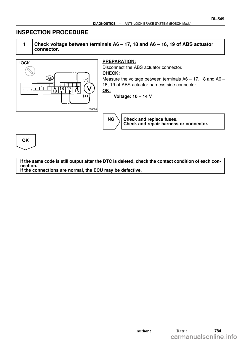
1 Check voltage between terminals A6 ± 17, 18 and A6 ± 16, 19 of ABS actuator
connector.
PREPARATION:
Disconnect the ABS actuator connector.
CHECK:
Measure the voltage between terminals A6 ± 17, 18 and A6 ±
16, 19 of ABS actuator harness side connector.
OK:
Voltage: 10 ± 14 V
NG Check and replace fuses.
Check and repair harness or connector.
OK
If the same code is still output after the DTC is deleted, check the contact condition of each con-
nection.
If the connections are normal, the ECU may be defective.
Page 2970 of 4770
F03949
Actuator Assembly
BatteryActuator Assembly
MAINB±GF4 1 ALT
FL
Block 1F5 B±G3
ABS
12 3
Engine
Room R/B
No.3L
L
18
A6
+B+BA6
Valve Relay
Motor Relay17
A6 16 GND2
W±BEA
W±B
W±B 19
A6GND1 ECU DI±550
± DIAGNOSTICSANTI±LOCK BRAKE SYSTEM (BOSCH Made)
785 Author�: Date�:
DTC 21, 22, 23, 24 ABS Solenoid Valve Circuit
CIRCUIT DESCRIPTION
This solenoid goes on when signals are received from the ECU and controls the pressure acting on the wheel
cylinders thus controlling the braking force.
DTC No.DTC Detecting ConditionTrouble Area
21, 22, 23, 24Solenoid valve signal does not match to the check result.�Each solenoid valve
Fail safe function:
If trouble occurs in the actuator solenoid valve circuit, the ECU cuts off current to the ABS solenoid valve
relay and prohibits ABS control.
WIRING DIAGRAM
DI042±08
Page 2971 of 4770
± DIAGNOSTICSANTI±LOCK BRAKE SYSTEM (BOSCH Made)
DI±551
786 Author�: Date�:
INSPECTION PROCEDURE
1 Check the DTC once more.
PREPARATION:
(a) Clear the DTC (See page DI±539).
(b) Turn the ignition switch OFF.
CHECK:
Turn the ignition switch ON, and check if the same DTC is stored in the memory.
NO No problem.
YES
Replace ABS ECU.
Page 2972 of 4770

787 Author�: Date�:
DTC31, 32, 33, 34, 35, 36, 38, 39Sp")
BR3583
BR3582F00010
RotorSpeed Sensor
Magnet
To ECU
+V
±VHigh Speed
Low Speed
CoilNS
DI±552
± DIAGNOSTICSANTI±LOCK BRAKE SYSTEM (BOSCH Made)
787 Author�: Date�:
DTC31, 32, 33, 34, 35, 36, 38, 39Speed Sensor Circuit
CIRCUIT DESCRIPTION
The speed sensor detects wheel speed and sends the ap-
propriate signals to the ECU. These signals are used to control
the ABS system. The front and rear rotors each have 48 serra-
tions.
When the rotors rotate, the magnetic field emitted by the perma-
nent magnet in the speed sensor generates an AC voltage.
Since the frequency of this AC voltage changes in direct propor-
tion to the speed of the rotor, the frequency is used by the ECU
to detect the speed of each wheel.
DTC No.DTC Detecting ConditionTrouble Area
31, 32, 33, 34
Detection of any of conditions from 1. through 3.:
1. Vehicle speed is more than 40 km/h (25 mph), pulses
are not input for 0.01 sec.
2. After the initial start or restart and when the vehicle
speed has reached 12 km/h (7 mph), the wheel with 0
km/h (0 mph) of wheel speed is detected.
3. After the initial start or restart and when the vehicle
speed has reached 70 km/h (44 mph), front wheel with 0
km/h (0 mph) of wheel speed is detected.
�Right front, left front, right rear, left rear speed sensor
�Each speed sensor circuit
�Sensor installation
�ECU
35, 36, 38, 39Detecting abnormality in the resistance value of each speed
sensor.�Right front, left front, right rear, left rear speed sensor
�Each speed sensor circuit
�ECU
HINT:
�DTC No. 31 and 35 are for the right front speed sensor.
�DTC No. 32 and 36 are for the left front speed sensor.
�DTC No. 33 and 38 are for the right rear speed sensor.
�DTC No. 34 and 39 are for the left rear speed sensor.
Fail safe function:
If trouble occurs in the speed sensor circuit, the ECU cuts off current to the ABS solenoid valve relay and
prohibits ABS control.
DI043±04
Page 2973 of 4770
F00086
Right Front
Speed Sensor
Left Front
Speed Sensor
Right Rear
Speed Sensor
Left Rear
Speed SensorECU
FR+
FR±
FL+
FL±
RR+
RR±
RL+
RL± A6
A6
A6
A6
A6
A6
A6
A65
4
7
6
3
1
9
8 W
B
R
G
P
L
Y
BRR
G
PP
L
L
Y
Y
BR
BR 2
1
2
1
1
2
1
2IK2
IL1IK3
ID1IK2
IL1 IK3
ID1IK3
IK3 22 1
6
1
3
93
9 6Right Front
Speed Sensor
Left Front
Speed Sensor
Right Rear
Speed Sensor
Left Rear
Speed SensorECU
FR+
FR±
FL+
FL±
RR+
RR±
RL+
RL± A6
A6
A6
A6
A6
A6
A6
A65
4
7
6
3
1
9
8 W
B
R
G
P
L
Y
BRR
G
PP
L
L
Y
Y
BR
BR 2
1
2
1
1
2
1
2IK2
IL1IK3
ID1IK2
IL1 IK3
ID1IK3
IK3 22 1
6
1
3
93
9 6
± DIAGNOSTICSANTI±LOCK BRAKE SYSTEM (BOSCH Made)
DI±553
788 Author�: Date�:
WIRING DIAGRAM