Page 2953 of 4770
± DIAGNOSTICSANTI±LOCK BRAKE SYSTEM (DENSO Made)
DI±533
768 Author�: Date�:
2 Check for open and short circuit in harness and connector between ABS ECU
and DLC2 or DLC1, DLC2 or DLC1 and body ground (See page IN±31).
NG Repair or replace harness or connector.
OK
Check and replace ABS ECU.
Page 2954 of 4770
F00172
J/C
EC BRA
ABR
3
16 DLC1
Ts E
1
R±Y
II38
R±Y
A198
TsABS ECU
J22: (1MZ±FE)
J23: (5S±FE)
J/C
BRA
ABR
3
16 DLC1
Ts E
1
R±Y
II38
R±Y
A198
TsABS ECU
J22: (1MZ±FE)
J23: (5S±FE)
AB0119S08096
F00446DLC1 DLC1
DLC1
DLC1DLC1
Ts
DLC1 E1
ON
DI±534
± DIAGNOSTICSANTI±LOCK BRAKE SYSTEM (DENSO Made)
769 Author�: Date�:
Ts Terminal Circuit
CIRCUIT DESCRIPTION
The sensor check circuit detects abnormalities in the speed sensor signal which cannot be detected with
the DTC check.
Connecting terminals Ts and E
1 of the DLC1 in the engine compartment starts the check.
WIRING DIAGRAM
INSPECTION PROCEDURE
1 Check voltage between terminals Ts and E1 of DLC1.
CHECK:
(a) Turn the ignition switch ON.
(b) Measure voltage between terminals Ts and E
1 of DLC1.
OK:
Voltage: 10 ± 14 V
OK If ABS warning light does not blink even after Ts
and E
1 are connected, the ECU may be defec-
tive.
NG
DI03S±03
Page 2955 of 4770
± DIAGNOSTICSANTI±LOCK BRAKE SYSTEM (DENSO Made)
DI±535
770 Author�: Date�:
2 Check for open and short circuit in harness and connector between ABS ECU
and DLC1, DLC1 and body ground (See page IN±31).
NG Repair or replace harness or connector.
OK
Check and replace ABS ECU.
Page 2960 of 4770

BR3890
F02201
DLC1
TsTc E1
BR3904
0.13 sec. 0.12 sec.
ON
OFF DI±540
± DIAGNOSTICSANTI±LOCK BRAKE SYSTEM (BOSCH Made)
775 Author�: Date�:
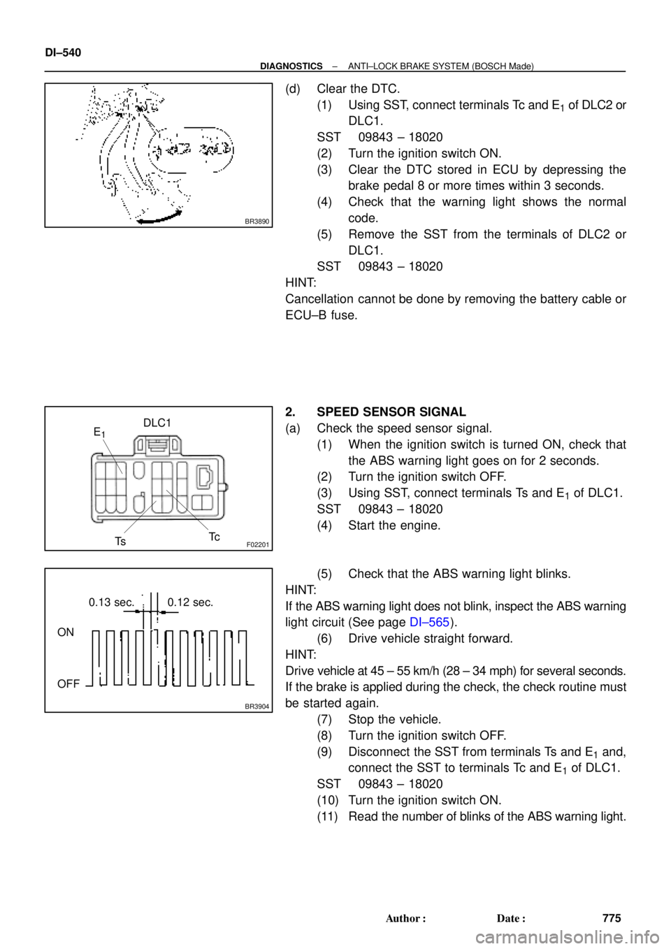
(d) Clear the DTC.
(1) Using SST, connect terminals Tc and E
1 of DLC2 or
DLC1.
SST 09843 ± 18020
(2) Turn the ignition switch ON.
(3) Clear the DTC stored in ECU by depressing the
brake pedal 8 or more times within 3 seconds.
(4) Check that the warning light shows the normal
code.
(5) Remove the SST from the terminals of DLC2 or
DLC1.
SST 09843 ± 18020
HINT:
Cancellation cannot be done by removing the battery cable or
ECU±B fuse.
2. SPEED SENSOR SIGNAL
(a) Check the speed sensor signal.
(1) When the ignition switch is turned ON, check that
the ABS warning light goes on for 2 seconds.
(2) Turn the ignition switch OFF.
(3) Using SST, connect terminals Ts and E
1 of DLC1.
SST 09843 ± 18020
(4) Start the engine.
(5) Check that the ABS warning light blinks.
HINT:
If the ABS warning light does not blink, inspect the ABS warning
light circuit (See page DI±565).
(6) Drive vehicle straight forward.
HINT:
Drive vehicle at 45 ± 55 km/h (28 ± 34 mph) for several seconds.
If the brake is applied during the check, the check routine must
be started again.
(7) Stop the vehicle.
(8) Turn the ignition switch OFF.
(9) Disconnect the SST from terminals Ts and E
1 and,
connect the SST to terminals Tc and E
1 of DLC1.
SST 09843 ± 18020
(10) Turn the ignition switch ON.
(11) Read the number of blinks of the ABS warning light.
Page 2962 of 4770

DI03W±11
DI±542
± DIAGNOSTICSANTI±LOCK BRAKE SYSTEM (BOSCH Made)
777 Author�: Date�:
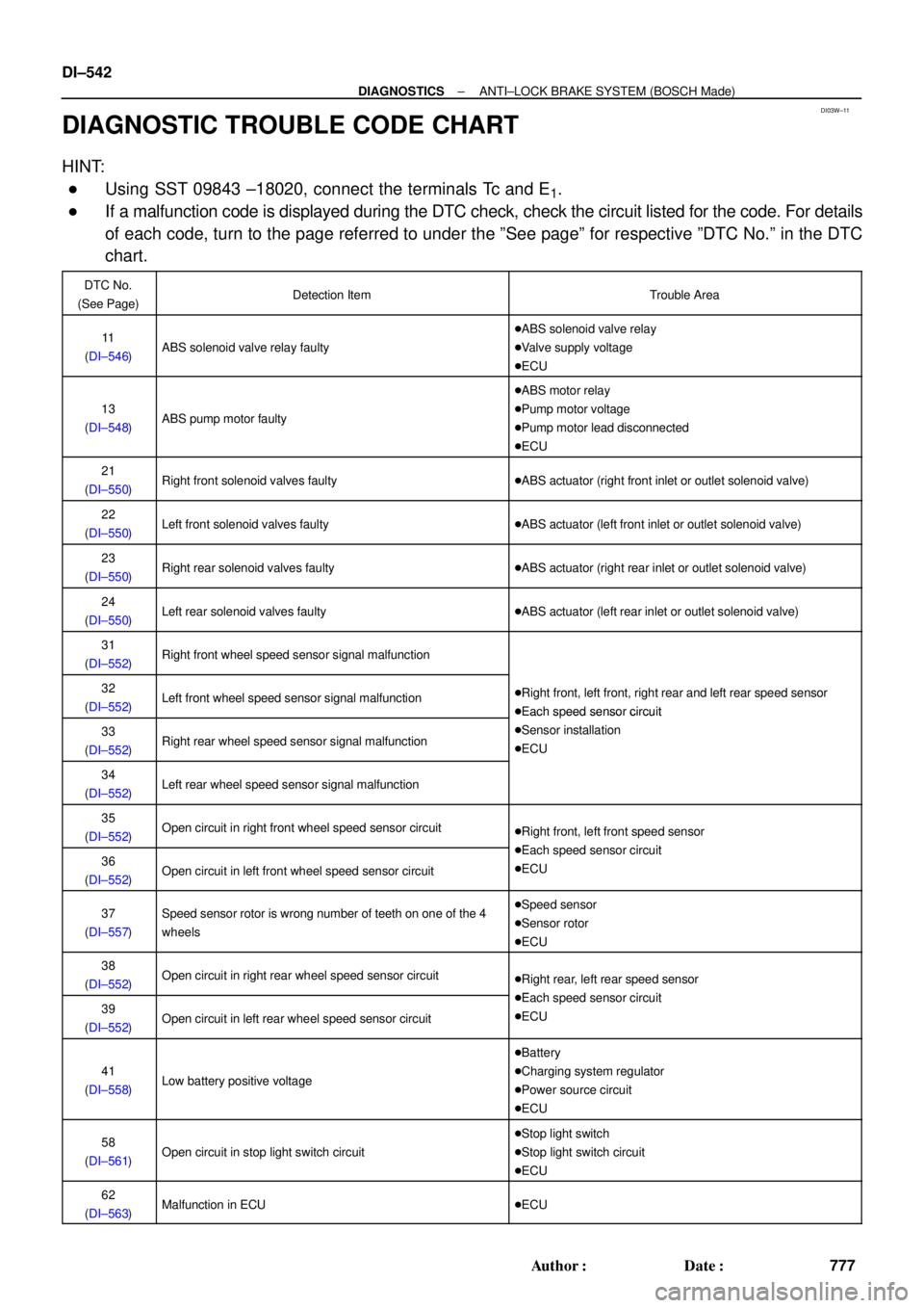
DIAGNOSTIC TROUBLE CODE CHART
HINT:
�Using SST 09843 ±18020, connect the terminals Tc and E1.
�If a malfunction code is displayed during the DTC check, check the circuit listed for the code. For details
of each code, turn to the page referred to under the ºSee pageº for respective ºDTC No.º in the DTC
chart.
DTC No.
(See Page)Detection ItemTrouble Area
11
(DI±546)ABS solenoid valve relay faulty
�ABS solenoid valve relay
�Valve supply voltage
�ECU
13
(DI±548)ABS pump motor faulty
�ABS motor relay
�Pump motor voltage
�Pump motor lead disconnected
�ECU
21
(DI±550)Right front solenoid valves faulty�ABS actuator (right front inlet or outlet solenoid valve)
22
(DI±550)Left front solenoid valves faulty�ABS actuator (left front inlet or outlet solenoid valve)
23
(DI±550)Right rear solenoid valves faulty�ABS actuator (right rear inlet or outlet solenoid valve)
24
(DI±550)Left rear solenoid valves faulty�ABS actuator (left rear inlet or outlet solenoid valve)
31
(DI±552)Right front wheel speed sensor signal malfunction
32
(DI±552)Left front wheel speed sensor signal malfunction�Right front, left front, right rear and left rear speed sensor
�Each speed sensor circuit
33
(DI±552)Right rear wheel speed sensor signal malfunction
�Each s eed sensor circuit
�Sensor installation
�ECU
34
(DI±552)Left rear wheel speed sensor signal malfunction
35
(DI±552)Open circuit in right front wheel speed sensor circuit�Right front, left front speed sensor
Eh d i it36
(DI±552)Open circuit in left front wheel speed sensor circuit
�Each speed sensor circuit
�ECU
37
(DI±557)Speed sensor rotor is wrong number of teeth on one of the 4
wheels�Speed sensor
�Sensor rotor
�ECU
38
(DI±552)Open circuit in right rear wheel speed sensor circuit�Right rear, left rear speed sensor
Eh d i it39
(DI±552)Open circuit in left rear wheel speed sensor circuit
�Each speed sensor circuit
�ECU
41
(DI±558)Low battery positive voltage
�Battery
�Charging system regulator
�Power source circuit
�ECU
58
(DI±561)Open circuit in stop light switch circuit
�Stop light switch
�Stop light switch circuit
�ECU
62
(DI±563)Malfunction in ECU�ECU
Page 2963 of 4770
DI03X±05
F01175
ABS Actuator
(w/ ECU, Relay)Front Speed Sensor
DLC1
DLC2Sensor Rotor
Rear Speed Sensor
Stop Light Switch ABS Warning Light
Sensor Rotor
Front Speed Sensor
± DIAGNOSTICSANTI±LOCK BRAKE SYSTEM (BOSCH Made)
DI±543
778 Author�: Date�:
PARTS LOCATION
Page 2964 of 4770

DI1JN±03
F00050
A6
12 345678
910 1112 13 14 15
16 17 181920 21 2223 24 2526 DI±544
± DIAGNOSTICSANTI±LOCK BRAKE SYSTEM (BOSCH Made)
779 Author�: Date�:
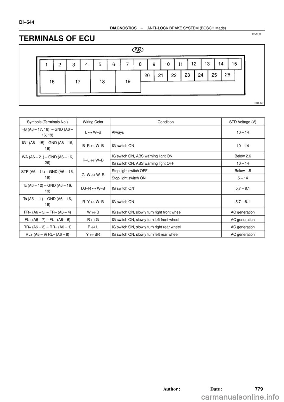
TERMINALS OF ECU
Symbols (Terminals No.)Wiring ColorConditionSTD Voltage (V)
+B (A6 ± 17, 18) ± GND (A6 ±
16, 19)L e W±BAlways10 ± 14
IG1 (A6 ± 15) ± GND (A6 ± 16,
19)B±R e W±BIG switch ON10 ± 14
WA (A6 ± 21) ± GND (A6 ± 16,RLWBIG switch ON, ABS warning light ONBelow 2.6WA (A6 21) GND (A6 16,
26)R±L e W±BIG switch ON, ABS warning light OFF10 ± 14
STP (A6 ± 14) ± GND (A6 ± 16,GWWBStop light switch OFFBelow 1.5STP (A6 14) GND (A6 16,
19)G±W e W±BStop light switch ON5 ± 14
Tc (A6 ± 12) ± GND (A6 ± 16,
19)LG±R e W±BIG switch ON5.7 ± 8.1
Ts (A6 ± 11) ± GND (A6 ± 16,
19)R±Y e W±BIG switch ON5.7 ± 8.1
FR+ (A6 ± 5) ± FR± (A6 ± 4)W e BIG switch ON, slowly turn right front wheelAC generation
FL+ (A6 ± 7) ± FL± (A6 ± 6)R e GIG switch ON, slowly turn left front wheelAC generation
RR+ (A6 ± 3) ± RR± (A6 ± 1)P e LIG switch ON, slowly turn right rear wheelAC generation
RL+ (A6 ± 9) RL± (A6 ± 8)Y e BRIG switch ON, slowly turn left rear wheelAC generation
Page 2965 of 4770

DI03Z±10
± DIAGNOSTICSANTI±LOCK BRAKE SYSTEM (BOSCH Made)
DI±545
780 Author�: Date�:
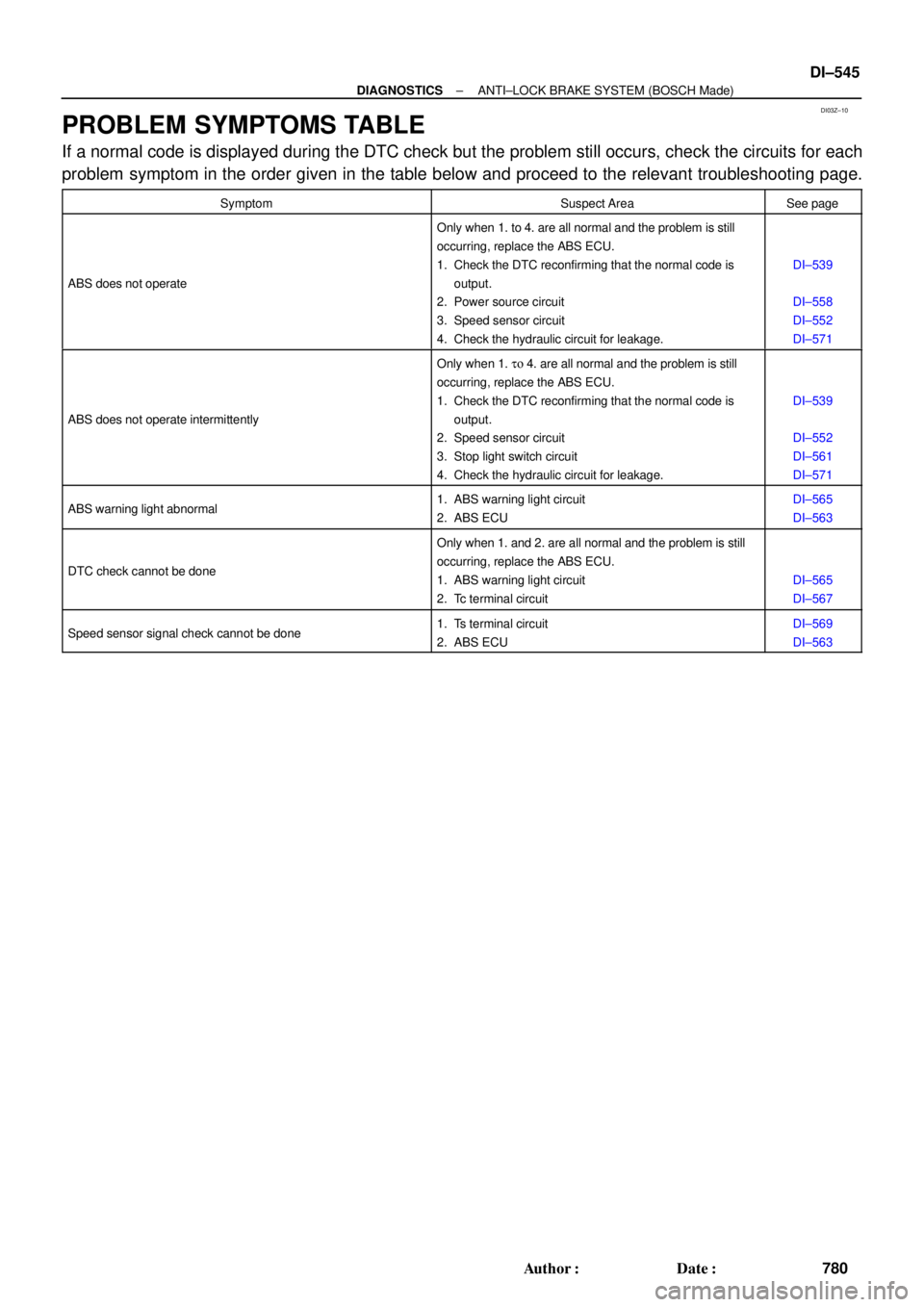
PROBLEM SYMPTOMS TABLE
If a normal code is displayed during the DTC check but the problem still occurs, check the circuits for each
problem symptom in the order given in the table below and proceed to the relevant troubleshooting page.
SymptomSuspect AreaSee page
ABS does not operate
Only when 1. to 4. are all normal and the problem is still
occurring, replace the ABS ECU.
1. Check the DTC reconfirming that the normal code is
output.
2. Power source circuit
3. Speed sensor circuit
4. Check the hydraulic circuit for leakage.
DI±539
DI±558
DI±552
DI±571
ABS does not operate intermittently
Only when 1. to 4. are all normal and the problem is still
occurring, replace the ABS ECU.
1. Check the DTC reconfirming that the normal code is
output.
2. Speed sensor circuit
3. Stop light switch circuit
4. Check the hydraulic circuit for leakage.
DI±539
DI±552
DI±561
DI±571
ABS warning light abnormal1. ABS warning light circuit
2. ABS ECUDI±565
DI±563
DTC check cannot be done
Only when 1. and 2. are all normal and the problem is still
occurring, replace the ABS ECU.
1. ABS warning light circuit
2. Tc terminal circuit
DI±565
DI±567
Speed sensor signal check cannot be done1. Ts terminal circuit
2. ABS ECUDI±569
DI±563