Page 3006 of 4770
F00042
1
2 3
4 5 6
1 2 3
4 5 6
1 2 3
4 5 6 Open
Continuity
Continuity
Open Continuity
(+) (±)
DI±586
± DIAGNOSTICSABS & TRACTION CONTROL SYSTEM
821 Author�: Date�:
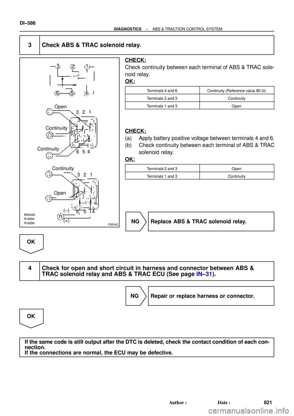
3 Check ABS & TRAC solenoid relay.
CHECK:
Check continuity between each terminal of ABS & TRAC sole-
noid relay.
OK:
Terminals 4 and 6Continuity (Reference value 80 W)
Terminals 2 and 3Continuity
Terminals 1 and 3Open
CHECK:
(a) Apply battery positive voltage between terminals 4 and 6.
(b) Check continuity between each terminal of ABS & TRAC
solenoid relay.
OK:
Terminals 2 and 3Open
Terminals 1 and 3Continuity
NG Replace ABS & TRAC solenoid relay.
OK
4 Check for open and short circuit in harness and connector between ABS &
TRAC solenoid relay and ABS & TRAC ECU (See page IN±31).
NG Repair or replace harness or connector.
OK
If the same code is still output after the DTC is deleted, check the contact condition of each con-
nection.
If the connections are normal, the ECU may be defective.
Page 3007 of 4770

F03413
Battery2
Engine Room R/B No. 3
MAIN B±G F4F5
FL
BlockABS
12
3
1ALT1
31 B±GABS & TRAC
Motor Relay
4
33
3GR±L
GR±R24
A15
1
A15ABS & TRAC ECU
MR
R+
MT
A1514
R±W
A83 ABS & TRAC Actuator
W±R2
A8
1
A8
W±B
EA
± DIAGNOSTICSABS & TRACTION CONTROL SYSTEM
DI±587
822 Author�: Date�:
DTC 13, 14 ABS & TRAC Motor Relay Circuit
CIRCUIT DESCRIPTION
The ABS & TRAC motor relay supplies power to the ABS & TRAC pump motor. While the ABS is activated,
the ECU switches the ABS & TRAC motor relay ON and operates the ABS & TRAC pump motor.
DTC No.DTC Detecting ConditionTrouble Area
13
Conditions 1. to 3. are detected:
1. Malfunction of motor relay monitor
2. Battery voltage will not exceed more than 17.0 V within
2.16 sec.
3. Battery voltage will not become less than 9.5 V within
2.16 sec., or after the motor relay is ON and motor relay
monitor does not ON.
�ABS & TRAC motor relay
�ABS & TRAC motor relay circuit
�ECU
14Motor relay is OFF, and motor relay monitor is ON , which
continues for 20.16 sec. or more.
Fail safe function:
If any trouble occurs in the ABS & TRAC motor relay circuit, the ECU cuts off current to the ABS & TRAC
solenoid relay and prohibits ABS control and TRAC control.
WIRING DIAGRAM
DI04K±04
Page 3008 of 4770
 (±)
Engine Room
R/B No. 31
2
34 (+) (±)
Engine Room
R/B No. 31
2
34 (+) (±)
Engine Room
R/B No. 31
2
34 (+) (±)
Engine Room
R/B No. 3
F00056
ABS & TRAC
Motor
Relay
M2
A15
MT")
F00049
1
2
34 (+) (±)
Engine Room
R/B No. 31
2
34 (+) (±)
Engine Room
R/B No. 31
2
34 (+) (±)
Engine Room
R/B No. 31
2
34 (+) (±)
Engine Room
R/B No. 3
F00056
ABS & TRAC
Motor
Relay
M2
A15
MT
32
2
3
ABS & TRAC
Actuator
ECU
ABS & TRAC
Motor
Relay
M2
A15
MT
32
2
3
ABS & TRAC
Actuator
ECU
ABS & TRAC
Motor
Relay
M2
A15
MT
32
2
3
ABS & TRAC
Actuator
ECU
A8
ABS & TRAC
Motor
Relay
A8 M2
A15
MT
32
2
3
ABS & TRAC
Actuator
ECUEngine Room R/B
No. 3
DI±588
± DIAGNOSTICSABS & TRACTION CONTROL SYSTEM
823 Author�: Date�:
INSPECTION PROCEDURE
1 Check voltage between terminal 1 of Engine Room R/B No. 3 (for ABS & TRAC
motor relay) and body ground.
PREPARATION:
Remove ABS & TRAC motor relay from Engine Room R/B No.
3.
CHECK:
Measure voltage between terminal 1 of Engine Room R/B No.
3 (for ABS & TRAC motor relay) and body ground.
OK:
Voltage: 10 ± 14 V
NG Check and repair harness or connector.
OK
2 Check continuity between terminal 2 of ABS & TRAC motor relay and terminal
MT of ABS & TRAC ECU.
CHECK:
Check continuity between terminal 2 of Engine Room R/B No.
3 (for ABS & TRAC motor relay) and terminal MT of ABS &
TRAC ECU.
OK:
Continuity
HINT:
There is a resistance of 4 ~ 6 W between terminals A8 ± 2 and
A8 ± 3 of ABS & TRAC actuator.
NG Repair or replace harness or ABS & TRAC
actuator.
OK
Page 3009 of 4770
F00044
1 2
3 4
1 2
3 4
1 2
3 4 ContinuityOpen
Continuity
(+) (±)
± DIAGNOSTICSABS & TRACTION CONTROL SYSTEM
DI±589
824 Author�: Date�:
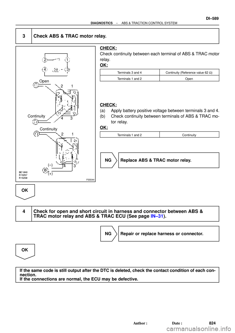
3 Check ABS & TRAC motor relay.
CHECK:
Check continuity between each terminal of ABS & TRAC motor
relay.
OK:
Terminals 3 and 4Continuity (Reference value 62 W)
Terminals 1 and 2Open
CHECK:
(a) Apply battery positive voltage between terminals 3 and 4.
(b) Check continuity between terminals of ABS & TRAC mo-
tor relay.
OK:
Terminals 1 and 2Continuity
NG Replace ABS & TRAC motor relay.
OK
4 Check for open and short circuit in harness and connector between ABS &
TRAC motor relay and ABS & TRAC ECU (See page IN±31).
NG Repair or replace harness or connector.
OK
If the same code is still output after the DTC is deleted, check the contact condition of each con-
nection.
If the connections are normal, the ECU may be defective.
Page 3010 of 4770

DI±590
± DIAGNOSTICSABS & TRACTION CONTROL SYSTEM
825 Author�: Date�:
DTC 21 to 28 ABS & TRAC Actuator Solenoid Circuit
CIRCUIT DESCRIPTION
This solenoid goes on when signals are received from the ECU and controls the pressure acting on the wheel
cylinders thus controlling the braking force.
DTC No.DTC Detecting ConditionTrouble Area
21
�ABS actuator
�SFRR or SFRH circuit
�ECU
22
�ABS actuator
�SFLR or SFLH circuit
�ECU
23Conditions 1. and 2. or 3. continue for 0.48 sec. or more:
1 Recoveryprohibit runpulse is not output solenoid relay
�ABS actuator
�SRRR or SRRH circuit
�ECU
24
1. Recovery prohibit run pulse is not output, solenoid relay
is ON, AST voltage of ECU terminal is 8.0 V or more,
and solenoid output has no change between the last
time and this time.�ABS actuator
�SRLR or SRLH circuit
�ECU
25
time and this time.
2. Solenoid output is ON, pressure holding solenoid moni-
tor voltage is more than 1.0 V or pressure eduction sole-
noid monitor voltage is more than 1.5 V.
�ABS actuator
�SMC1 circuit
�ECU
26
g
3. Solenoid output is OFF, solenoid monitor voltage is more
than ±1.0 V AST voltage of ECU.�ABS actuator
�SMC2 circuit
�ECU
27
�ABS actuator
�SRC1 circuit
�ECU
28
�ABS actuator
�SRC2 circuit
�ECU
Fail safe function:
If any trouble occurs in the actuator solenoid circuit, the ECU cuts off current to the ABS & TRAC solenoid
relay and prohibits ABS control and TRAC control.
DI04L±04
Page 3011 of 4770

F03952
SRLH
10
SR
R+
SFLR
SRRR
SRC2
AST
10
SFLR
SRRR
SRC2
AST Battery
MAIN
B±G1F4
ALT
1 B±G
F5
FL
Block
W±B
EA 3
333 2 ABS
12 Engine Room R/B No. 3
ABS & TRAC
Solenoid
Relay
16 33
3
4
5
W±L DLC1GR
GR±R
4A8ABS & TRAC ECU
ABS & TRAC ActuatorA7
A7
A7
A7
A7
A7
A7
A7
A7
A7
A7
A7
A89
10
12
11
3
4
6
5
7
2
8
1
5R±B
G±Y
L±B
W±R
W±R
LG±B
W±L
R±G
B±R
B±Y
Y±R
Y±B
R11
A15
1A15
13
A15
25
A15
2A17
8A17
26
A15
12
A15
1A17
7A17
5A17
4A17
12
A17
6A17
A15
SFLH
SRRH
SFRR
SRLR
SRC1
SMC1
SMC2 SFRH
F00057
1 2 3
4 5 6
7
8 9 10 11 12
A7
4
1 2 3
4 5 6
7
8 9 10 11 12
A7
4
1 2 3
4 5 6
7
8 9 10 11 12
A7
4
1 2 3
4 5 6
7
8 9 10 11 12
A7
4
1 2 3
4 5 6
7
8 9 10 11 12
A7
41 2 3
4 5 6
7
8 9 10 11 12A8
A74
± DIAGNOSTICSABS & TRACTION CONTROL SYSTEM
DI±591
826 Author�: Date�:
WIRING DIAGRAM
INSPECTION PROCEDURE
1 Check ABS & TRAC actuator solenoid.
PREPARATION:
Disconnect the 2 connectors from ABS & TRAC actuator.
CHECK:
Check continuity between terminals A8 ± 4 and A7 ± 1, 2, 3, 4,
5, 6, 7, 8, 9, 10, 11, 12 of ABS & TRAC actuator connector.
OK:
Continuity
HINT:
Resistance of each solenoid coil is 1.2 W.
NG Replace ABS & TRAC actuator.
OK
Page 3012 of 4770
DI±592
± DIAGNOSTICSABS & TRACTION CONTROL SYSTEM
827 Author�: Date�:
2 Check for open and short circuit in harness and connector between ABS &
TRAC ECU and actuator (See page IN±31).
NG Repair or replace harness or connector.
OK
If the same code is still output after the DTC is deleted, check the contact condition of each con-
nection.
If the connections are normal, the ECU may be defective.
Page 3013 of 4770

BR3583
BR3582F00010
RotorSpeed Sensor
Magnet
To ECU
+V
±VHigh Speed
Low Speed
CoilNS
± DIAGNOSTICSABS & TRACTION CONTROL SYSTEM
DI±593
828 Author�: Date�:
DTC31, 32, 33, 34Speed Sensor Circuit
CIRCUIT DESCRIPTION
The speed sensor detects wheel speed and sends the ap-
propriate signals to the ECU. These signals are used to control
the ABS and TRAC system. The front and rear rotors each have
48 serrations.
When the rotors rotate, the magnetic field emitted by the perma-
nent magnet in the speed sensor generates an AC voltage.
Since the frequency of this AC voltage changes in direct propor-
tion to the speed of the rotor, the frequency is used by the ECU
to detect the speed of each wheel.
DTC No.DTC Detecting ConditionTrouble Area
31, 32, 33, 34
Detection of any of conditions from 1. through 3.:
1. ABS is in non±operation, wheel speed is 10 km/h or
more, one eighth of maximum wheel speed is greater
than the minimum wheel speed, one eighth of maximum
wheel speed is smaller than the rear maximum wheel
speed or momentary interruption of both the rear wheels
are shown in the 15 sec. or more continuously.
2. ABS is in non±operation, momentary interruption of
speed sensor occurs 7 times or more in the mean time
of switching the ignition switch ON and OFF or vehicle
speed is 20 km/h (12 mph) or more and the condition of
noise interference or non±noise interference occurs 75
times or more within 5 sec.
3. Vehicle is at a stop, malfunction signal of vehicle speed
sensor hardware open circuit is ON for 1.02 sec. contin-
uously since starting the checking of a certain vehicle.
�Right front, left front, right rear, left rear speed sensor
�Each speed sensor circuit
�Speed sensor rotor
�ECU
HINT:
�DTC No. 31 is for the right front speed sensor.
�DTC No. 32 is for the left front speed sensor.
�DTC No. 33 is for the right rear speed sensor.
�DTC No. 34 is for the left rear speed sensor.
Fail safe function:
If any trouble occurs in the speed sensor circuit, the ECU cuts off current to the ABS & TRAC solenoid relay
and prohibits ABS control and TRAC control.
DI1JP±03