Page 2254 of 4770
BR0AX±03
BR1532
R00285
BR1534
SST
BR1535
SST BR±32
± BRAKEREAR DRUM BRAKE
2055 Author�: Date�:
REMOVAL
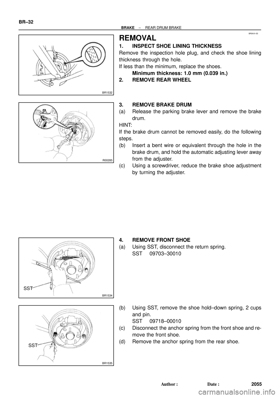
1. INSPECT SHOE LINING THICKNESS
Remove the inspection hole plug, and check the shoe lining
thickness through the hole.
If less than the minimum, replace the shoes.
Minimum thickness: 1.0 mm (0.039 in.)
2. REMOVE REAR WHEEL
3. REMOVE BRAKE DRUM
(a) Release the parking brake lever and remove the brake
drum.
HINT:
If the brake drum cannot be removed easily, do the following
steps.
(b) Insert a bent wire or equivalent through the hole in the
brake drum, and hold the automatic adjusting lever away
from the adjuster.
(c) Using a screwdriver, reduce the brake shoe adjustment
by turning the adjuster.
4. REMOVE FRONT SHOE
(a) Using SST, disconnect the return spring.
SST 09703±30010
(b) Using SST, remove the shoe hold±down spring, 2 cups
and pin.
SST 09718±00010
(c) Disconnect the anchor spring from the front shoe and re-
move the front shoe.
(d) Remove the anchor spring from the rear shoe.
Page 2255 of 4770
R00248
SST
Z03633
BR1540
SST
± BRAKEREAR DRUM BRAKE
BR±33
2056 Author�: Date�:
5. REMOVE REAR SHOE
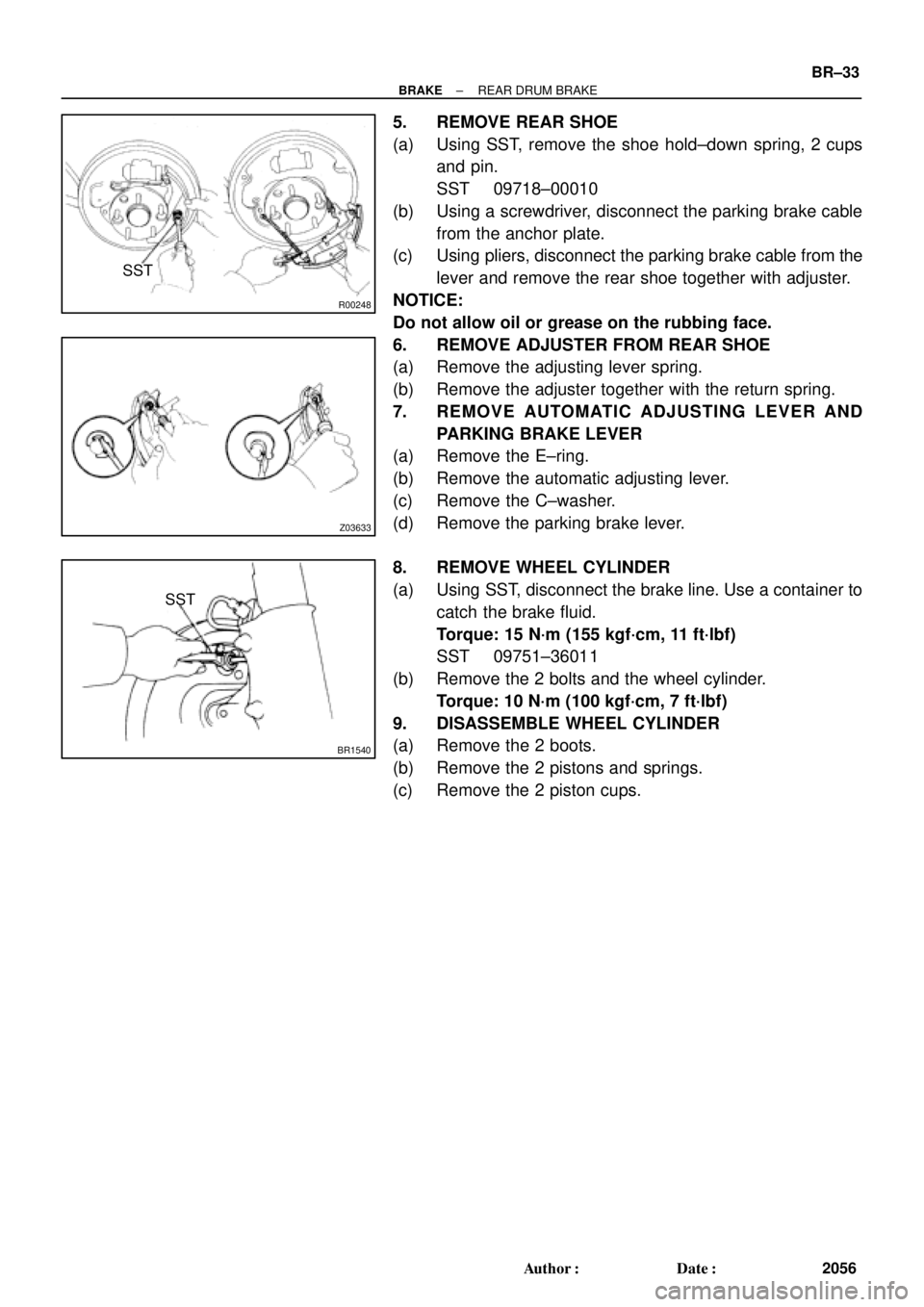
(a) Using SST, remove the shoe hold±down spring, 2 cups
and pin.
SST 09718±00010
(b) Using a screwdriver, disconnect the parking brake cable
from the anchor plate.
(c) Using pliers, disconnect the parking brake cable from the
lever and remove the rear shoe together with adjuster.
NOTICE:
Do not allow oil or grease on the rubbing face.
6. REMOVE ADJUSTER FROM REAR SHOE
(a) Remove the adjusting lever spring.
(b) Remove the adjuster together with the return spring.
7. REMOVE AUTOMATIC ADJUSTING LEVER AND
PARKING BRAKE LEVER
(a) Remove the E±ring.
(b) Remove the automatic adjusting lever.
(c) Remove the C±washer.
(d) Remove the parking brake lever.
8. REMOVE WHEEL CYLINDER
(a) Using SST, disconnect the brake line. Use a container to
catch the brake fluid.
Torque: 15 N´m (155 kgf´cm, 11 ft´lbf)
SST 09751±36011
(b) Remove the 2 bolts and the wheel cylinder.
Torque: 10 N´m (100 kgf´cm, 7 ft´lbf)
9. DISASSEMBLE WHEEL CYLINDER
(a) Remove the 2 boots.
(b) Remove the 2 pistons and springs.
(c) Remove the 2 piston cups.
Page 2259 of 4770
BR0B1±03
R00591
R00514
R10387
± BRAKEREAR BRAKE PAD
BR±37
2060 Author�: Date�:
REPLACEMENT
1. REMOVE REAR WHEEL
Remove the wheel and temporarily fasten the disc with the hub
nuts.
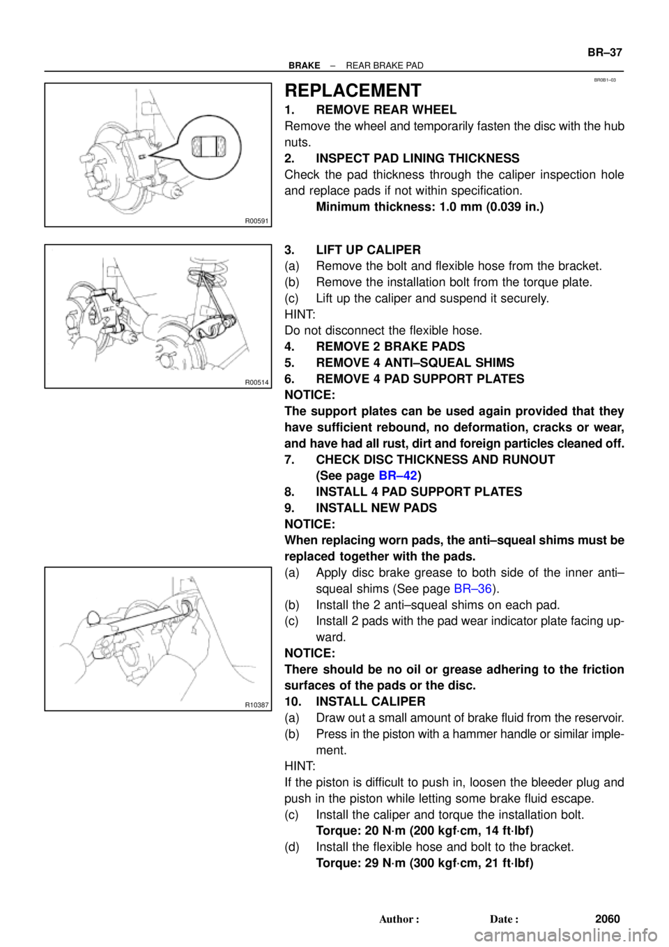
2. INSPECT PAD LINING THICKNESS
Check the pad thickness through the caliper inspection hole
and replace pads if not within specification.
Minimum thickness: 1.0 mm (0.039 in.)
3. LIFT UP CALIPER
(a) Remove the bolt and flexible hose from the bracket.
(b) Remove the installation bolt from the torque plate.
(c) Lift up the caliper and suspend it securely.
HINT:
Do not disconnect the flexible hose.
4. REMOVE 2 BRAKE PADS
5. REMOVE 4 ANTI±SQUEAL SHIMS
6. REMOVE 4 PAD SUPPORT PLATES
NOTICE:
The support plates can be used again provided that they
have sufficient rebound, no deformation, cracks or wear,
and have had all rust, dirt and foreign particles cleaned off.
7. CHECK DISC THICKNESS AND RUNOUT
(See page BR±42)
8. INSTALL 4 PAD SUPPORT PLATES
9. INSTALL NEW PADS
NOTICE:
When replacing worn pads, the anti±squeal shims must be
replaced together with the pads.
(a) Apply disc brake grease to both side of the inner anti±
squeal shims (See page BR±36).
(b) Install the 2 anti±squeal shims on each pad.
(c) Install 2 pads with the pad wear indicator plate facing up-
ward.
NOTICE:
There should be no oil or grease adhering to the friction
surfaces of the pads or the disc.
10. INSTALL CALIPER
(a) Draw out a small amount of brake fluid from the reservoir.
(b) Press in the piston with a hammer handle or similar imple-
ment.
HINT:
If the piston is difficult to push in, loosen the bleeder plug and
push in the piston while letting some brake fluid escape.
(c) Install the caliper and torque the installation bolt.
Torque: 20 N´m (200 kgf´cm, 14 ft´lbf)
(d) Install the flexible hose and bolt to the bracket.
Torque: 29 N´m (300 kgf´cm, 21 ft´lbf)
Page 2260 of 4770
BR±38
± BRAKEREAR BRAKE PAD
2061 Author�: Date�:
11. INSTALL REAR WHEEL
Torque: 103 N´m (1.050 kgf´cm, 76 ft´lbf)
12. DEPRESS BRAKE PEDAL SEVERAL TIMES
13. CHECK THAT FLUID LEVEL IS AT MAX LINE
Page 2262 of 4770
BR0B3±03
W03263
W03264
BR±40
± BRAKEREAR BRAKE CALIPER
2063 Author�: Date�:
REMOVAL
1. REMOVE REAR WHEEL
Torque: 103 N´m (1.050 kgf´cm, 76 ft´lbf)
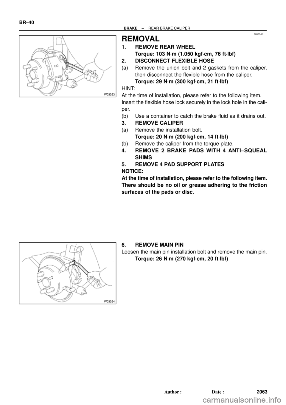
2. DISCONNECT FLEXIBLE HOSE
(a) Remove the union bolt and 2 gaskets from the caliper,
then disconnect the flexible hose from the caliper.
Torque: 29 N´m (300 kgf´cm, 21 ft´lbf)
HINT:
At the time of installation, please refer to the following item.
Insert the flexible hose lock securely in the lock hole in the cali-
per.
(b) Use a container to catch the brake fluid as it drains out.
3. REMOVE CALIPER
(a) Remove the installation bolt.
Torque: 20 N´m (200 kgf´cm, 14 ft´lbf)
(b) Remove the caliper from the torque plate.
4. REMOVE 2 BRAKE PADS WITH 4 ANTI±SQUEAL
SHIMS
5. REMOVE 4 PAD SUPPORT PLATES
NOTICE:
At the time of installation, please refer to the following item.
There should be no oil or grease adhering to the friction
surfaces of the pads or disc.
6. REMOVE MAIN PIN
Loosen the main pin installation bolt and remove the main pin.
Torque: 26 N´m (270 kgf´cm, 20 ft´lbf)
Page 2268 of 4770
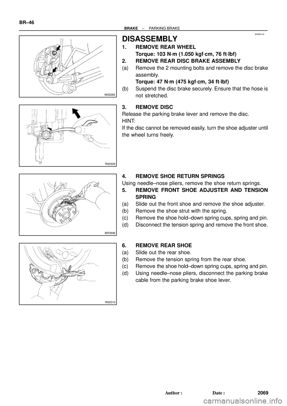
BR0B9±03
W03265
R00309
BR3948
R00310
BR±46
± BRAKEPARKING BRAKE
2069 Author�: Date�:
DISASSEMBLY
1. REMOVE REAR WHEEL
Torque: 103 N´m (1.050 kgf´cm, 76 ft´lbf)
2. REMOVE REAR DISC BRAKE ASSEMBLY
(a) Remove the 2 mounting bolts and remove the disc brake
assembly.
Torque: 47 N´m (475 kgf´cm, 34 ft´lbf)
(b) Suspend the disc brake securely. Ensure that the hose is
not stretched.
3. REMOVE DISC
Release the parking brake lever and remove the disc.
HINT:
If the disc cannot be removed easily, turn the shoe adjuster until
the wheel turns freely.
4. REMOVE SHOE RETURN SPRINGS
Using needle±nose pliers, remove the shoe return springs.
5. REMOVE FRONT SHOE ADJUSTER AND TENSION
SPRING
(a) Slide out the front shoe and remove the shoe adjuster.
(b) Remove the shoe strut with the spring.
(c) Remove the shoe hold±down spring cups, spring and pin.
(d) Disconnect the tension spring and remove the front shoe.
6. REMOVE REAR SHOE
(a) Slide out the rear shoe.
(b) Remove the tension spring from the rear shoe.
(c) Remove the shoe hold±down spring cups, spring and pin.
(d) Using needle±nose pliers, disconnect the parking brake
cable from the parking brake shoe lever.
Page 2271 of 4770
BR0BC±03
W04698
SST
SST
± BRAKEPROPORTIONING VALVE (P VALVE)
BR±49
2072 Author�: Date�:
PROPORTIONING VALVE (P VALVE)
INSPECTION
1. INSTALL LSPV GAUGE (SST)
SST 09709±29018
2. BLEED AIR FROM FLUID PRESSURE GAUGE
3. RAISE MASTER CYLINDER PRESSURE AND CHECK REAR WHEEL CYLINDER OR CALIPER
PRESSURE
Master cylinder fluid pressureRear brake cylinder fluid pressure
5S±FE engine:
2,452 kPa (25 kgf/cm2, 356 psi)2,452 kPa (25 kgf/cm2, 356 psi)
7,845 kPa (80 kgf/cm2, 1,138 psi)4,413 kPa (45 kgf/cm2, 640 psi)
1MZ±FE engine:
2,942 kPa (30 kgf/cm2, 427 psi)2,942 kPa (30 kgf/cm2, 427 psi)
7,845 kPa (80 kgf/cm2, 1,138 psi)5,982 kPa (61 kgf/cm2, 868 psi)
If the rear brake cylinder pressure is incorrect, replace the P valve assembly.
4. REMOVE LSPV GAUGE (SST) AND BLEED BRAKE SYSTEM (See page BR±4)
5. CHECK FOR LEAKS
Page 2327 of 4770
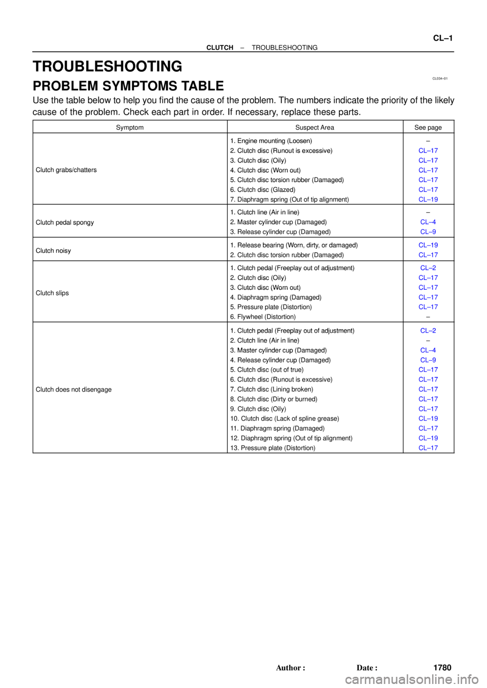
CL034±01
± CLUTCHTROUBLESHOOTING
CL±1
1780 Author�: Date�:
TROUBLESHOOTING
PROBLEM SYMPTOMS TABLE
Use the table below to help you find the cause of the problem. The numbers indicate the priority of the likely
cause of the problem. Check each part in order. If necessary, replace these parts.
SymptomSuspect AreaSee page
1. Engine mounting (Loosen)±1. Engine mounting (Loosen)
2. Clutch disc (Runout is excessive)
±
CL±17
2. Clutch disc (Runout is excessive)
3. Clutch disc (Oily)
CL±17
CL±17
Clutch grabs/chatters
3. Clutch disc (Oily)
4. Clutch disc (Worn out)
CL±17
CL±17Clutch grabs/chatters4. Clutch disc (Worn out)
5. Clutch disc torsion rubber (Damaged)
CL±17
CL±175. Clutch disc torsion rubber (Damaged)
6. Clutch disc (Glazed)
CL 17
CL±176. Clutch disc (Glazed)
7. Diaphragm spring (Out of tip alignment)
CL 17
CL±19
1. Clutch line (Air in line)±
Clutch pedal spongy
1. Clutch line (Air in line)
2. Master cylinder cup (Damaged)
±
CL±4
Clutch edal s ongy2. Master cylinder cu (Damaged)
3. Release cylinder cup (Damaged)
CL 4
CL±9
1 Release bearing (Worn dirty or damaged)CL 19Clutch noisy1. Release bearing (Worn, dirty, or damaged)
2Cl hdi i bb (D d)
CL±19
CL 17Clutch noisy2. Clutch disc torsion rubber (Damaged)CL±17
1. Clutch pedal (Freeplay out of adjustment)CL±21. Clutch edal (Free lay out of adjustment)
2. Clutch disc (Oily)
CL±2
CL±17
Cl t h li
2. Clutch disc (Oily)
3. Clutch disc (Worn out)
CL±17
CL±17Clutch slips3. Clutch disc (Worn out)
4. Diaphragm spring (Damaged)
CL 17
CL±174. Dia hragm s ring (Damaged)
5. Pressure plate (Distortion)
CL 17
CL±175. Pressure late (Distortion)
6. Flywheel (Distortion)
CL 17
±
1 Clutchpedal (Freeplay out of adjustment)CL±21. Clutch pedal (Freeplay out of adjustment)
2 Clutch line (Air in line)CL±2
2. Clutch line (Air in line)
3 Master cylinder cup(Damaged)
±
CL 43. Master cylinder cup (Damaged)
4 Release cylinder cup(Damaged)
CL±4
CL 94. Release cylinder cup (Damaged)
5 Clutch disc (out of true)
CL±9
CL 175. Clutch disc (out of true)
6 Cl tch disc (R no t is e cessi e)
CL±17
CL 17
Cl t h d t di
6. Clutch disc (Runout is excessive)
7 Cl t h di (Li i b k )
CL±17
CL 17Clutch does not disengage7. Clutch disc (Lining broken)
8 Cl t h di (Di t b d)
CL±17
CL 178. Clutch disc (Dirty or burned)
Cl h di (Oil )
CL±17
CL9. Clutch disc (Oily)CL±17
10. Clutch disc (Lack of spline grease)CL±19
11. Diaphragm spring (Damaged)CL±17gg(g)
12. Diaphragm spring (Out of tip alignment)CL±19gg( g)
13. Pressure plate (Distortion)CL±17