Page 627 of 4770
INSTALLATION
Radiator Support to
Front Fender
Bracket.
1. Temporarily install the new parts and mea-
sure each part in accordance with the body
dimension diagram.
HINT: First install the radiator upper support.
BODY PANEL REPLACEMENTRE-5
Page 628 of 4770
FRONT CROSSMEMBER SIDE GUSSET (ASSY)
REMOVAL (With the radiator side support removed.)
Front Bumper Arm
Mounting Bracket.
1. Replace the front bumper arm mounting
bracket at the same time.
BODY PANEL REPLACEMENTRE-6
Page 632 of 4770
RADIATOR SUPPORT (ASSY)
REMOVAL
Front Side Member
Extension
1. After removing the front side member exten-
sion, removing the radiator support.
BODY PANEL REPLACEMENTRE-10
Page 634 of 4770
FRONT FENDER FRONT APRON (ASSY)
REMOVAL (With the radiator support removed.)
BODY PANEL REPLACEMENTRE-12
Page 638 of 4770
FRONT FENDER APRON (ASSY)
REMOVAL (With the radiator support, cowl top side panel
removed.)
BODY PANEL REPLACEMENTRE-16
Page 704 of 4770
K±k
1,526
(60.08)
Vehicle Dimensions Left e Right
C±K
or
c±k
826
(35.52)1,712
(67.40)C±k
or
c±K
HINT: For symbols, capital letters indicate right side of vehicle,
small letters indicate left side of vehicle (Seen from rear.)
mm (in.)
(Three±Dimensional Distance)
Hole dia.
10 (0.39)
10 (0.39)
12 (0.47)
8 (0.315) nut
3R (0.12) Name
Radiator support standard hole
Radiator support standard hole
Front crossmember standard hole
Hood hinge installation nut±rear
Front Fender apron to cowl side member cut±out
portion Symbol
G, g
H, h
I, i
J, j
K, k Hole dia.
6 (0.24) nut
11 (0.43)
6 (0.24) nut
7 (0.28)
13 (0.51)
15 (0.59) Name
Front fender installation nut±front
Front spring support hole±inner
Front fender installation nut±raar
Cowl ventilator louver installation hole
Front side member standard hole
Front side member working hole Symbol
A, a
B, b
C, c
D
E, e
F, f
BODY DIMENSION DRAWINGS
ENGINE COMPARTMENT
BODY DIMENSIONSDI-3
Page 927 of 4770

'99camry U
213
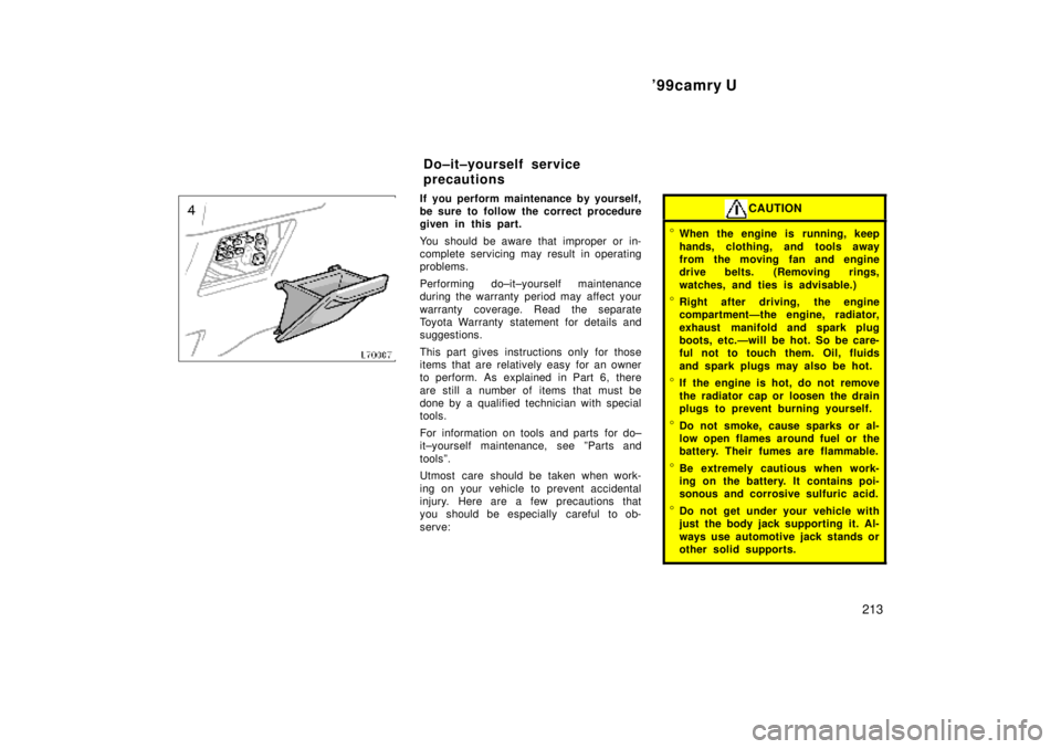
If you perform maintenance by yourself,
be sure to follow the correct procedure
given in this part.
You should be aware that improper or in-
complete servicing may result in operating
problems.
Performing do±it±yourself maintenance
during the warranty period may affect your
warranty coverage. Read the separate
Toyota Warranty statement for details and
suggestions.
This part gives instructions only for those
items that are relatively easy for an owner
to perform. As explained in Part 6, there
are still a number of items that must be
done by a qualified technician with special
tools.
For information on tools and parts for do±
it±yourself maintenance, see ºParts and
toolsº.
Utmost care should be taken when work-
ing on your vehicle to prevent accidental
injury. Here are a few precautions that
you should be especially careful to ob-
serve:CAUTION
�When the engine is running, keep
hands, clothing, and tools away
from the moving fan and engine
drive belts. (Removing rings,
watches, and ties is advisable.)
�Right after driving, the engine
compartmentÐthe engine, radiator,
exhaust manifold and spark plug
boots, etc.Ðwill be hot. So be care-
ful not to touch them. Oil, fluids
and spark plugs may also be hot.
�If the engine is hot, do not remove
the radiator cap or loosen the drain
plugs to prevent burning yourself.
�Do not smoke, cause sparks or al-
low open flames around fuel or the
battery. Their fumes are flammable.
�Be extremely cautious when work-
ing on the battery. It contains poi-
sonous and corrosive sulfuric acid.
�Do not get under your vehicle with
just the body jack supporting it. Al-
ways use automotive jack stands or
other solid supports.
Do±it±yourself service
precautions
Page 1174 of 4770
F
3: Engine Room R/B No.3Radiator Upper Support RH (See Page 18)
(TMMK Made w/ ABS and Traction Control)
(TMC Made w/ ABS, w/ ABS and Traction Control)
3: Fusible Link BlockRadiator Upper Support RH (See Page 18)
(TMMK Made w/ ABS w/o Traction Control)