Page 1497 of 4770
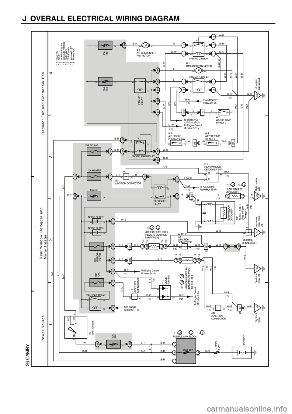
J OVERALL ELECTRICAL WIRING DIAGRAM
1
234
26 CAMRY
1F 2F
1A 1A
1B 40A
AM1
1B 11K 22ACC
IG1 AM1 4
10A
MIRROR±
HEAT ER
1 0 A HEAT ER 15A ECU±I G
40A DEF
30A
RDI30A
CDS
1T 5 1D 41J71R 31A6
2H 2
5IM1 5IE1
8ID11L 11J12
1V 3
IJ Right kic k
panelIE Co wl s i de
panel LHIGInstrument
panel brace
LHBORi ght quart er
pillar 20 IE1
20 IM11K 1 1B 4
2K 62B2
1 2
M
2 1
3 4
2 1
3 53 5
2 1
4
2F 4 2C 2 1J 13
1G 72 3
1 2
2EA1 1EA1
1 2
5 3
4 1 1
1 11 2G 7 2F 2 2C 12G1
1 2
5 3
1 2
M 11
11 5IK1
L±B L±B B±R
1II1
1
EBLef t radiat or
side supportG±W
B±R(
*1)
W±R
W± B
B±R W± B
B±R
W± BL(
*1)
L(
*1)
B±W
(
*2)
G± W
L±W L±W W±B
W± B
B±RW±B W± B W± B
W± R
B±R R
G±W
L
L
B±R
B BY±G(
*8)
W± B
A
A11 1
2
A22
FAN NO. 2 RELAY
R 1
RA DI A TOR FA N MOT OR
FAN NO. 3 RELAY
W 5
WATER TEMP.
SW NO. 2 To Di o de(
A/ C)
<27±2><29±3>
A 3
A/ C SI NGLE
PRESSURE SWW 4
WATER TEMP.
SW NO. 1
J32
JUNCTI ON CONNECTOR
FAN NO. 1
RELAY
DEFOGGER
RELAYFro m MG CLT
Relay< 27±2>
AA
AA
J38
JUNCTION
CONNECTOR
J39
JUNCTION
CONNECTOR NOISE FILTER
B±Y
B±YB±Y
B±YW± B
W± B W± B
W± B W± B
W± B
W±B
B±G 100A ALT
B±R B±R
B±R B±R
I16
IGNITION SW
BATTERY FL MAIN
3. 0WFUSI BLE LINK BLOCK
B±R B±R
B± R
Power SourceR ear W indow Defogger and
M irror H ea terRadiator Fan and Condenser Fan
1DB±R B±R
B± Y B±Y
B±R
(
*2)
LL
(
*1) L L
(
*1)
ENGINE MAIN RELAY
2 1
2 1
3 5
W± B
1C 9 1C 61J11
To Engine Control
Module< 2±10>
AA
31
2J12
JUNCTION
CONNECTOR
B±Y
(
*2) G± OG±O
(
*2) B±Y
(
*1)
B± R
(
*2)
To Engine Cont rol
Module< 3±6>
W±B D11
DIODE
(
Idle±Up) 10A
TAIL
TAIL LI GHT RELAY
* 1 : 1MZ±FE
* 2 : 5S±FE
1 2
WJ11
JUNCTI ON
CONNE CTOR
See Taillight
Sy st em< 11±1>
2J 13
G± W
(
*1)To Engine Cont rol
Module< 2±11>
W± B
A 1
A/C CONDENSER
FAN MOTOR
AA
W± B3 54
L±B
W± B
DIG
E
R 5
REAR WINDOW
DEFOGGER SW
B±R2 1
NOISE FILTERREAR WI NDOW
DEFOGGER
N 2
NOISE FILTER
(
Rear Window
Def ogger)1B
B
(
*3)
(
*4)(
*3)
* 3 : w/ Auto Antenna
* 4 : w/o Auto Antenna
6B 1A
4B 5A(
*6) (
*5)
(
*6) (
*5)6B 1A
4B 5A(
*5)
(
*6)
(
*5)
(
*6)* 5 : TMC Made
* 6 : TMMK Made
MI RROR HEAT ER RH
[ REMOTE CONTROL
MI RROR LH]B A R1 6 ,
R17 ,
MIRROR HEATER RH
[ RE MOT E CONT ROL
MIRROR RH]AB
REAR WINDOW
DEFOGGERB A R14 R15,
D F 4 F 7A, FF 9 , (
*5)(
*5) W± B
(
*6)
(
*5)
(
*5)(
*5) W± B(
*6)(
*8)
To A/C Co ntr ol
Assembly< 29±5> Y±G
(
*7)
(
*8)* 7 : Automatic A/C
* 8 : Manual A/C
W±B
(
*6)
Page 1501 of 4770
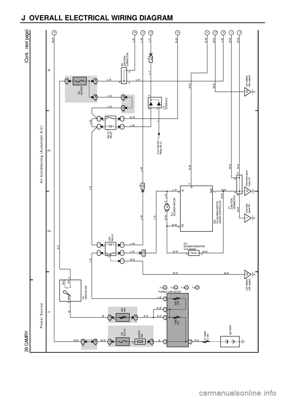
J OVERALL ELECTRICAL WIRING DIAGRAM
1
234
29 CAMRY(
Cont. next page)
2ACC
IG1 AM1 4
1K 2
40A
AM1
1B 1 1V 10
1W 3
2J 7
2 1
3 5
41 1
1 1 1 10A
ECU±B
2A 1
1E 1F 2F
1A1 EB2
EB Left radiator
s ide supportEB12
6 2
IGInst rument panel
brace LH1K 1
2 1
3 5 11
1110A
HEAT ER
1R 3 1W 2
2K 5 2C 9
IK27B
C
D
E
G
H
I
J F L±B L±B
L±W L±W
W± BB±W
W± B
L±B
W± B
W± B B±WL±Y L±WL±B
L±YW± R
A
L±B B±Y
L±W
L±R
W± B
W± R W± RB±R B±RB±RL±B
B±G B±W
L±WL±B L±B
L±B
L±B
W
I16
IGNITION SW
SHORT
PINHTR
RELAY
FL MAIN
3. 0W
B 8
BLOWER RESI STOR
(
Low Speed)
A3 3
A/C BLOWER MOTOR
LINEAR CONTROLLER
W± B
J11
JUNCTI ON
CONNE CTOR BATTERY32
D 3
DI ODE(
A/C)
Power SourceA ir Conditioning (
Automatic A/C)100A
ALT50A
HTR 1 2MG CLT
RE L AY
Fro m FAN NO. 3
Relay< 26±3>1
L 12
FUSIBLE LINK BLOCKC A F 4 F 6, EF 8 , FF 9 ,
M 12
IICowl si de
panel RH L±R
L±R B±W
W±BW±B B±W
W±B L±R
B±W
W± B B±W
43
A2
A1 B 3
BLOWER MOTOR
B± WJ32
JUNCTION
CONNECTOR A
AA
W± B
A A
B1CW
GND VM +B
SI
W± B
EBLef t radiat or
side support W± B
Page 1572 of 4770
AC0MB±02
N20279
AC±50
± AIR CONDITIONINGRECEIVER
2532 Author�: Date�:
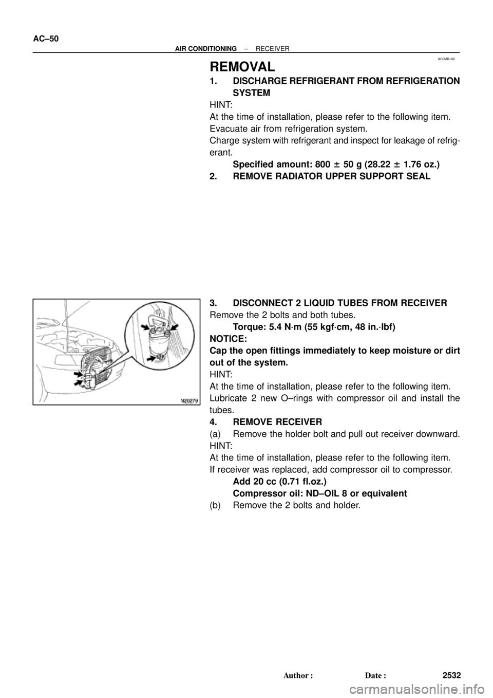
REMOVAL
1. DISCHARGE REFRIGERANT FROM REFRIGERATION
SYSTEM
HINT:
At the time of installation, please refer to the following item.
Evacuate air from refrigeration system.
Charge system with refrigerant and inspect for leakage of refrig-
erant.
Specified amount: 800 ± 50 g (28.22 ± 1.76 oz.)
2. REMOVE RADIATOR UPPER SUPPORT SEAL
3. DISCONNECT 2 LIQUID TUBES FROM RECEIVER
Remove the 2 bolts and both tubes.
Torque: 5.4 N´m (55 kgf´cm, 48 in.´lbf)
NOTICE:
Cap the open fittings immediately to keep moisture or dirt
out of the system.
HINT:
At the time of installation, please refer to the following item.
Lubricate 2 new O±rings with compressor oil and install the
tubes.
4. REMOVE RECEIVER
(a) Remove the holder bolt and pull out receiver downward.
HINT:
At the time of installation, please refer to the following item.
If receiver was replaced, add compressor oil to compressor.
Add 20 cc (0.71 fl.oz.)
Compressor oil: ND±OIL 8 or equivalent
(b) Remove the 2 bolts and holder.
Page 1575 of 4770
AC0ME±02
I03836
± AIR CONDITIONINGCONDENSER
AC±53
2535 Author�: Date�:
REMOVAL
1. DISCHARGE REFRIGERANT FROM REFRIGERATION
SYSTEM
HINT:
At the time of installation, please refer to the following item.
Evacuate air from refrigeration system.
Charge system with refrigerant and inspect for leakage of refrig-
erant.
Specified amount: 800 ± 50 g (28.22 ± 1.76 oz.)
2. REMOVE UPPER RADIATOR SUPPORTS
3. REMOVE RECEIVER AND HOLDER
(See page AC±50)
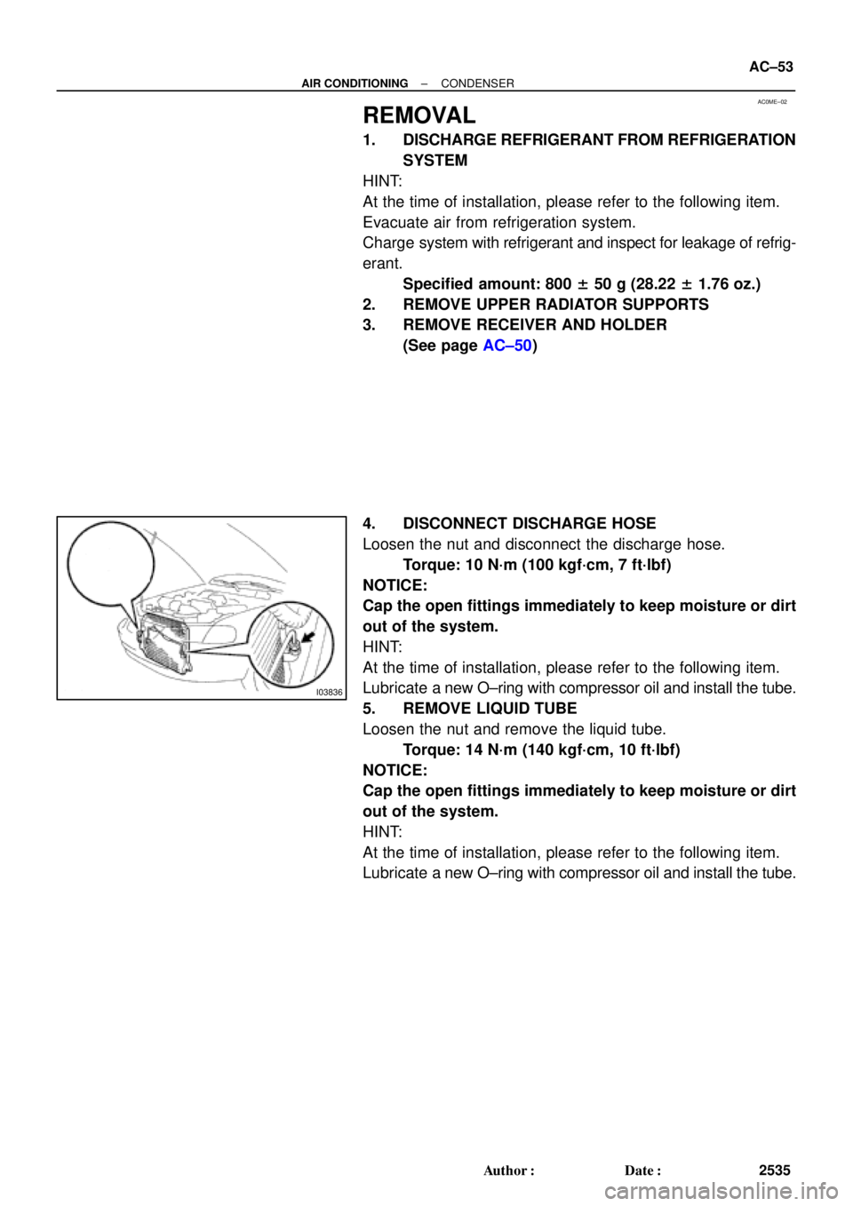
4. DISCONNECT DISCHARGE HOSE
Loosen the nut and disconnect the discharge hose.
Torque: 10 N´m (100 kgf´cm, 7 ft´lbf)
NOTICE:
Cap the open fittings immediately to keep moisture or dirt
out of the system.
HINT:
At the time of installation, please refer to the following item.
Lubricate a new O±ring with compressor oil and install the tube.
5. REMOVE LIQUID TUBE
Loosen the nut and remove the liquid tube.
Torque: 14 N´m (140 kgf´cm, 10 ft´lbf)
NOTICE:
Cap the open fittings immediately to keep moisture or dirt
out of the system.
HINT:
At the time of installation, please refer to the following item.
Lubricate a new O±ring with compressor oil and install the tube.
Page 2364 of 4770
CO06I±03
S05951
No.2 Electric
Cooling Fan
Connector
Radiator Assembly
Lower Radiator
Support
Lower Radiator Hose
Upper Radiator Hose
Oil Cooler Hose for A/TUpper Radiator Support
No.1 Electric Cooling Fan Connector
ECT Switch Connector
for Electric Cooling Fan Upper Radiator Support Radiator Reservoir Hose CO±16
± COOLING (5S±FE)RADIATOR
1590 Author�: Date�:
COMPONENTS
Page 2366 of 4770
CO06J±04
S05955
CO±18
± COOLING (5S±FE)RADIATOR
1592 Author�: Date�:
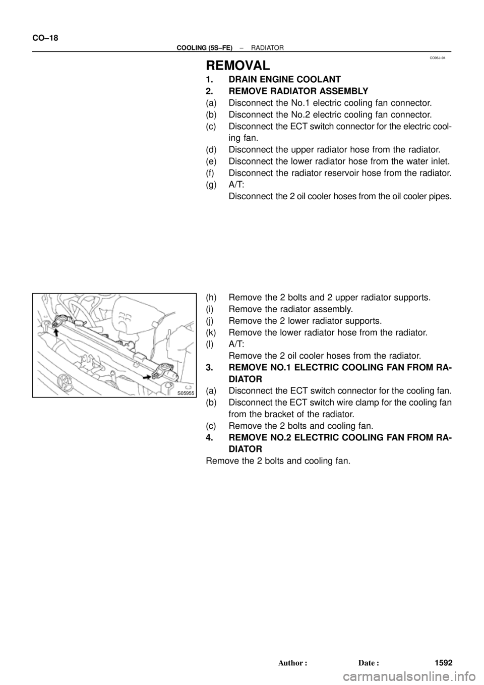
REMOVAL
1. DRAIN ENGINE COOLANT
2. REMOVE RADIATOR ASSEMBLY
(a) Disconnect the No.1 electric cooling fan connector.
(b) Disconnect the No.2 electric cooling fan connector.
(c) Disconnect the ECT switch connector for the electric cool-
ing fan.
(d) Disconnect the upper radiator hose from the radiator.
(e) Disconnect the lower radiator hose from the water inlet.
(f) Disconnect the radiator reservoir hose from the radiator.
(g) A/T:
Disconnect the 2 oil cooler hoses from the oil cooler pipes.
(h) Remove the 2 bolts and 2 upper radiator supports.
(i) Remove the radiator assembly.
(j) Remove the 2 lower radiator supports.
(k) Remove the lower radiator hose from the radiator.
(l) A/T:
Remove the 2 oil cooler hoses from the radiator.
3. REMOVE NO.1 ELECTRIC COOLING FAN FROM RA-
DIATOR
(a) Disconnect the ECT switch connector for the cooling fan.
(b) Disconnect the ECT switch wire clamp for the cooling fan
from the bracket of the radiator.
(c) Remove the 2 bolts and cooling fan.
4. REMOVE NO.2 ELECTRIC COOLING FAN FROM RA-
DIATOR
Remove the 2 bolts and cooling fan.
Page 2371 of 4770
CO06M±03
S05955
± COOLING (5S±FE)RADIATOR
CO±23
1597 Author�: Date�:
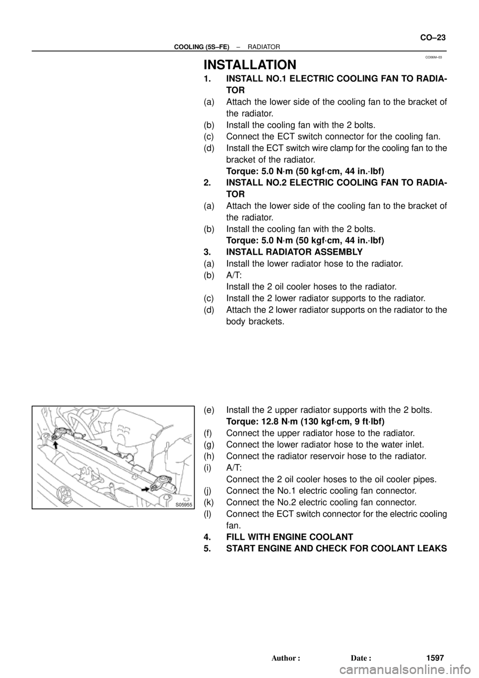
INSTALLATION
1. INSTALL NO.1 ELECTRIC COOLING FAN TO RADIA-
TOR
(a) Attach the lower side of the cooling fan to the bracket of
the radiator.
(b) Install the cooling fan with the 2 bolts.
(c) Connect the ECT switch connector for the cooling fan.
(d) Install the ECT switch wire clamp for the cooling fan to the
bracket of the radiator.
Torque: 5.0 N´m (50 kgf´cm, 44 in.´lbf)
2. INSTALL NO.2 ELECTRIC COOLING FAN TO RADIA-
TOR
(a) Attach the lower side of the cooling fan to the bracket of
the radiator.
(b) Install the cooling fan with the 2 bolts.
Torque: 5.0 N´m (50 kgf´cm, 44 in.´lbf)
3. INSTALL RADIATOR ASSEMBLY
(a) Install the lower radiator hose to the radiator.
(b) A/T:
Install the 2 oil cooler hoses to the radiator.
(c) Install the 2 lower radiator supports to the radiator.
(d) Attach the 2 lower radiator supports on the radiator to the
body brackets.
(e) Install the 2 upper radiator supports with the 2 bolts.
Torque: 12.8 N´m (130 kgf´cm, 9 ft´lbf)
(f) Connect the upper radiator hose to the radiator.
(g) Connect the lower radiator hose to the water inlet.
(h) Connect the radiator reservoir hose to the radiator.
(i) A/T:
Connect the 2 oil cooler hoses to the oil cooler pipes.
(j) Connect the No.1 electric cooling fan connector.
(k) Connect the No.2 electric cooling fan connector.
(l) Connect the ECT switch connector for the electric cooling
fan.
4. FILL WITH ENGINE COOLANT
5. START ENGINE AND CHECK FOR COOLANT LEAKS
Page 2398 of 4770
CO03N±03
B06399
Radiator
No.1 ECT Switch
No.2 Cooling Fan Connector
Upper Radiator Support Upper Radiator Hose
No.1 Cooling Fan Connector
No.1 ECT Switch Wire Connector Radiator Assembly
Lower Radiator
Support� O±Ring
A/T Oil Cooler Hose
Relay Block
(for Daytime Running Light System) No.1 ECT Switch Wire No.1 Cooling FanNo.2 Cooling Fan
Upper Radiator Support
Lower Radiator
Support
� Non±reusable part� O±Ring Drain PlugLower
Radiator
Hose A/T Oil Cooler Hose
Lower Radiator Hose CO±16
± COOLING (1MZ±FE)RADIATOR
1624 Author�: Date�:
COMPONENTS