Page 2400 of 4770
CO03O±03
S04725
B05937
Lower
Hose
Oil
Cooler
Hose
CO±18
± COOLING (1MZ±FE)RADIATOR
1626 Author�: Date�:
REMOVAL
HINT:
�At the time of installation, please refer to the following
items.
�Start the engine, and check for coolant and A/T fluid
leaks.
�Check the A/T fluid level. (See page DI±438)
1. DRAIN ENGINE COOLANT
2. CANADA:
DISCONNECT RELAY BLOCK (FOR DAYTIME
RUNNING LIGHT SYSTEM) FROM BATTERY
HOLD±DOWN CLAMP
3. DISCONNECT UPPER RADIATOR HOSE FROM
RADIATOR
4. DISCONNECT LOWER RADIATOR HOSE FROM
WATER INLET PIPE
5. DISCONNECT A/T OIL COOLER HOSES FROM OIL
COOLER PIPES
6. DISCONNECT NO.1 AND NO.2 COOLING FAN
CONNECTORS
7. DISCONNECT NO.1 ECT SWITCH WIRE CONNECTOR
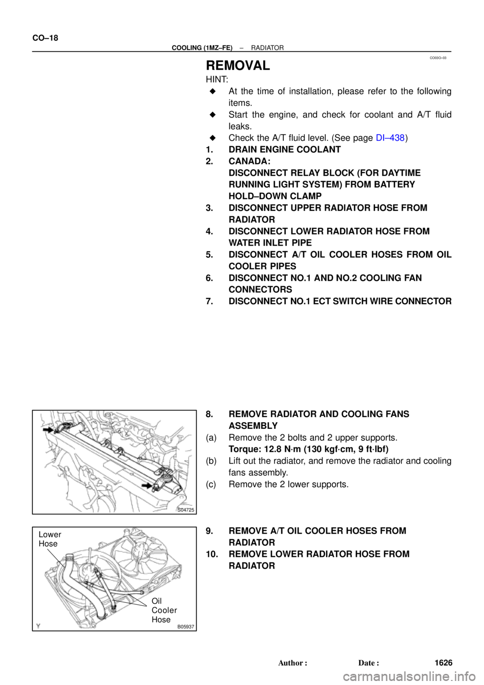
8. REMOVE RADIATOR AND COOLING FANS
ASSEMBLY
(a) Remove the 2 bolts and 2 upper supports.
Torque: 12.8 N´m (130 kgf´cm, 9 ft´lbf)
(b) Lift out the radiator, and remove the radiator and cooling
fans assembly.
(c) Remove the 2 lower supports.
9. REMOVE A/T OIL COOLER HOSES FROM
RADIATOR
10. REMOVE LOWER RADIATOR HOSE FROM
RADIATOR
Page 3456 of 4770
EM0YV±01
A02195
Radiator Reservoir Hose
Generator Drive BeltUpper Radiator
Hose
Support BracketFront Exhaust Pipe PS Oil Pressure Switch
ConnectorBattery TrayBattery
PS Pump Drive Belt
PS Pump
Support Stay Upper Radiator Support
Lower Radiator Hose
A/C Compressor
Cylinder Block Insulator
LH Front Fender Apron Seal
Oil Cooler Hose (A/T)
Cruise Control ActuatorEVAP Hose
Air Filter Upper Radiator
Support
EVAP Hose Hood
PCV Hose
Support
Bracket � Gasket
�
� Non±reusable part� Gasket
�Clamp
N´m (kgf´cm, ft´lbf)
62 (630, 46)
56 (570, 41)
�
: Specified torque
Washer Hose
for Windshield
No.1 Electric
Cooling Fan
Connector
ECT Switch
Connector No.2 Electric
Cooling Fan
ConnectorRadiator
Assembly
A/C Compressor
ConnectorLower Radiator
Support
RH Front Fender
Aplon Seal
Cruise
Control
Actuator
Connector
Battery
Hold±Down
ClampAir Cleaner
Case
VSV
Connector
for EVAP
EVAP
Hose
IAT Sensor
Connector
Air
Cleaner
Cap
EM±64
± ENGINE MECHANICAL (5S±FE)ENGINE UNIT
1236 Author�: Date�:
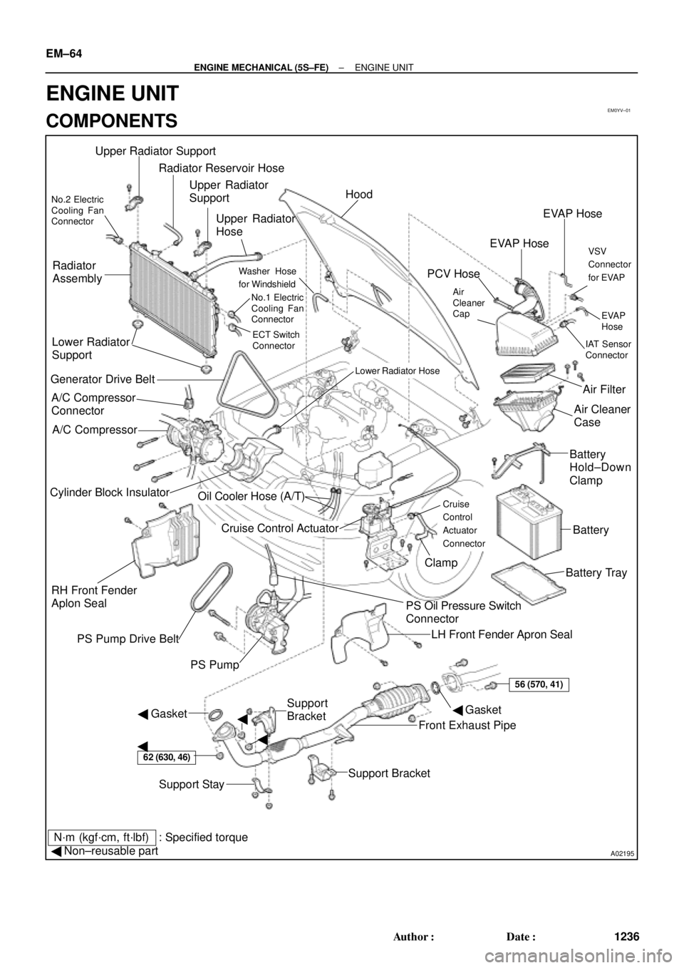
ENGINE UNIT
COMPONENTS
Page 3461 of 4770
EM08F±04
S05251
± ENGINE MECHANICAL (5S±FE)ENGINE UNIT
EM±69
1241 Author�: Date�:
REMOVAL
1. REMOVE HOOD
2. REMOVE FRONT FENDER APRON SEALS
3. DRAIN ENGINE COOLANT
4. DRAIN ENGINE OIL
5. DISCONNECT ACCELERATOR CABLE
6. REMOVE AIR CLEANER CAP
(a) Disconnect the IAT sensor connector.
(b) Disconnect the VSV connector for the EVAP
(c) Disconnect the PCV hose from the cylinder head cover.
(d) Disconnect the EVAP hose from the throttle body.
(e) Disconnect the EVAP hose from the VSV.
(f) Disconnect the 2 clamps, and disconnect the air cleaner
cap from the air cleaner case.
(g) Loosen hose clamp, and disconnect the air cleaner hose
from the throttle body.
(h) Remove the air cleaner cap and hose assembly.
7. REMOVE AIR CLEANER CASE
(a) Remove the air filter.
(b) Remove the 3 bolts and air cleaner case.
8. REMOVE BATTERY AND TRAY
9. REMOVE CRUISE CONTROL ACTUATOR
10. REMOVE RADIATOR (See page CO±18)
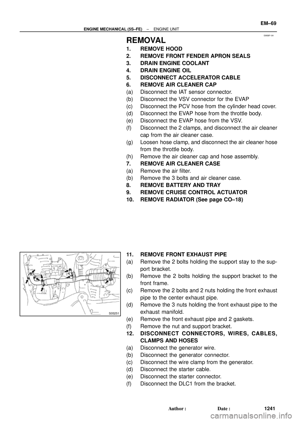
11. REMOVE FRONT EXHAUST PIPE
(a) Remove the 2 bolts holding the support stay to the sup-
port bracket.
(b) Remove the 2 bolts holding the support bracket to the
front frame.
(c) Remove the 2 bolts and 2 nuts holding the front exhaust
pipe to the center exhaust pipe.
(d) Remove the 3 nuts holding the front exhaust pipe to the
exhaust manifold.
(e) Remove the front exhaust pipe and 2 gaskets.
(f) Remove the nut and support bracket.
12. DISCONNECT CONNECTORS, WIRES, CABLES,
CLAMPS AND HOSES
(a) Disconnect the generator wire.
(b) Disconnect the generator connector.
(c) Disconnect the wire clamp from the generator.
(d) Disconnect the starter cable.
(e) Disconnect the starter connector.
(f) Disconnect the DLC1 from the bracket.
Page 3472 of 4770
S05251
EM±80
± ENGINE MECHANICAL (5S±FE)ENGINE UNIT
1252 Author�: Date�:
(b) Connect the generator connector.
(c) Install the wire clamp to the generator.
(d) Connect the starter cable.
(e) Connect the starter connector.
(f) Install the DLC1 to the bracket.
(g) Install the engine wire clamp to the bracket on the RH
fender apron.
(h) Connect the MAP sensor connector.
(i) Install the wire clamp to the bracket for the MAP sensor.
(j) Connect the VSV connector for the vapor pressure sen-
sor.
(k) Connect the 2 ground strap connectors to the RH fender
apron.
(l) Connect the 2 ground strap connectors to the LH fender
apron.
(m) Install the engine wire protector clamp to the battery
bracket.
(n) Install the engine wire to the clamp on the fuel filter.
(o) Connect the ground cable to the transaxle.
(p) Connect the brake booster vacuum hose to the intake
manifold.
(q) Connect the heater hose to the water outlet.
(r) Connect the heater hose to the water bypass pipe.
(s) Connect the fuel inlet hose to the fuel filter with 2 new gas-
kets and the union bolt.
Torque: 29 N´m (300 kgf´cm, 21 ft´lbf)
(t) Connect the MAP sensor vacuum hose to the gas filter on
the intake manifold.
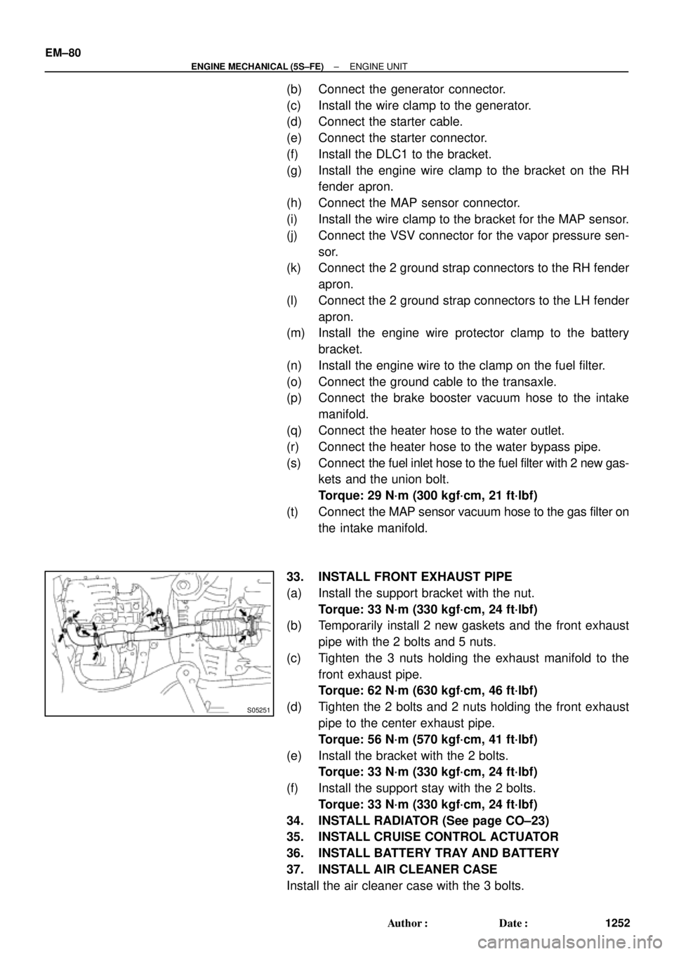
33. INSTALL FRONT EXHAUST PIPE
(a) Install the support bracket with the nut.
Torque: 33 N´m (330 kgf´cm, 24 ft´lbf)
(b) Temporarily install 2 new gaskets and the front exhaust
pipe with the 2 bolts and 5 nuts.
(c) Tighten the 3 nuts holding the exhaust manifold to the
front exhaust pipe.
Torque: 62 N´m (630 kgf´cm, 46 ft´lbf)
(d) Tighten the 2 bolts and 2 nuts holding the front exhaust
pipe to the center exhaust pipe.
Torque: 56 N´m (570 kgf´cm, 41 ft´lbf)
(e) Install the bracket with the 2 bolts.
Torque: 33 N´m (330 kgf´cm, 24 ft´lbf)
(f) Install the support stay with the 2 bolts.
Torque: 33 N´m (330 kgf´cm, 24 ft´lbf)
34. INSTALL RADIATOR (See page CO±23)
35. INSTALL CRUISE CONTROL ACTUATOR
36. INSTALL BATTERY TRAY AND BATTERY
37. INSTALL AIR CLEANER CASE
Install the air cleaner case with the 3 bolts.
Page 3575 of 4770
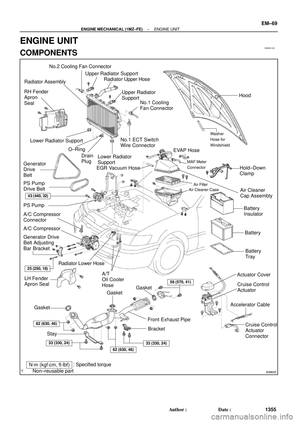
EM04X±04
A06650
No.2 Cooling Fan Connector
Upper Radiator Support
Radiator Assembly
RH Fender
Apron
Seal
Generator
Drive
Belt
A/C Compressor
ConnectorNo.1 ECT Switch
Wire Connector
Battery
Insulator
Battery
Battery
Tray Generator Drive
Belt Adjusting
Bar Bracket
LH Fender
Apron SealA/T
Oil Cooler
Hose
� Gasket A/C Compressor
43 (440, 32)
25 (250, 18)
�Non±reusable partStay
N´m (kgf´cm, ft´lbf)Bracket Front Exhaust Pipe: Specified torque� Gasket
62 (630, 46)
33 (330, 24)
�
62 (630, 46)
33 (330, 24)
� Gasket
56 (570, 41)
Actuator Cover
EGR Vacuum HoseUpper Radiator
Support
No.1 Cooling
Fan ConnectorHood
Hold±Down
Clamp
Washer
Hose for
Windshield
Air Filter
Air Cleaner Case
� O±Ring Lower Radiator Support
Drain
Plug
Lower Radiator
Support
Air Cleaner
Cap Assembly
Radiator Upper Hose
Cruise Control
Actuator
Cruise Control
Actuator
Connector
Accelerator Cable
PS Pump
Radiator Lower Hose
� PS Pump
Drive Belt
EVAP Hose
MAF Meter
Connector
± ENGINE MECHANICAL (1MZ±FE)ENGINE UNIT
EM±69
1355 Author�: Date�:
ENGINE UNIT
COMPONENTS
Page 3577 of 4770

EM04Y±03
S05048
± ENGINE MECHANICAL (1MZ±FE)ENGINE UNIT
EM±71
1357 Author�: Date�:
REMOVAL
1. REMOVE BATTERY AND TRAY
2. REMOVE HOOD
3. REMOVE ENGINE FENDER APRON SEALS
4. DRAIN ENGINE COOLANT
5. DRAIN ENGINE OIL
6. DISCONNECT ACCELERATOR CABLE
7. REMOVE AIR CLEANER CAP ASSEMBLY AND AIR
CLEANER CASE
8. REMOVE CRUISE CONTROL ACTUATOR
9. REMOVE RADIATOR (See page CO±18)
10. REMOVE FRONT EXHAUST PIPE
(a) Remove the 2 bolts holding the support stay to the sup-
port bracket.
(b) Remove the 2 bolts holding the support bracket to the
front frame.
(c) Remove the 2 bolts and 2 nuts holding the front exhaust
pipe to the center exhaust pipe.
(d) Remove the 4 nuts holding the front exhaust pipe to the
exhaust manifolds.
(e) Remove the front exhaust pipe and 3 gaskets.
11. DISCONNECT CONNECTORS, CABLE, CLAMPS
AND HOSES
(a) Disconnect the igniter connector on the LH fender apron.
(b) Disconnect the noise filter connector on the LH fender
apron.
(c) Disconnect the generator wire and connector.
(d) Disconnect the starter wire and connector.
(e) Disconnect the 2 ground strap connectors from the LH
fender apron.
(f) Disconnect the 2 ground strap connectors from the RH
fender apron.
(g) Disconnect the ground cable from the battery body brack-
et.
(h) Disconnect the engine wire protector clamp from the bat-
tery body bracket.
(i) Disconnect the engine wire clamp from the bracket on the
RH fender apron.
(j) Disconnect the engine wire clamp from the bracket on the
fuel filter.
Page 3585 of 4770
S05048
± ENGINE MECHANICAL (1MZ±FE)ENGINE UNIT
EM±79
1365 Author�: Date�:
(f) Connect the 2 ground strap connectors to the LH fender
apron.
(g) Connect the DLC1 to the RH fender apron.
(h) Connect the ground cable to the battery body bracket.
(i) Connect the engine wire protector clamp to the battery
body bracket.
(j) Connect the engine wire clamp to the bracket on the RH
fender apron.
(k) Connect the engine wire clamp to the bracket on the fuel
filter.
(l) Connect the brake booster vacuum hose to the air intake
chamber.
(m) Connect the engine coolant reservoir hose to the water
outlet.
(n) Connect the heater hose to the intake manifold.
(o) Connect the heater hose to the water inlet housing.
(p) Connect the fuel inlet hose to the fuel filter.
CAUTION:
Perform connecting operations of the fuel tube connector
(quick type) after observing the precautions.
(See page SF±6)
(q) Connect the purge hose to the pipe on the emission con-
trol valve set.
(r) Connect the 2 vacuum hoses to the vacuum tank for the
ACIS.
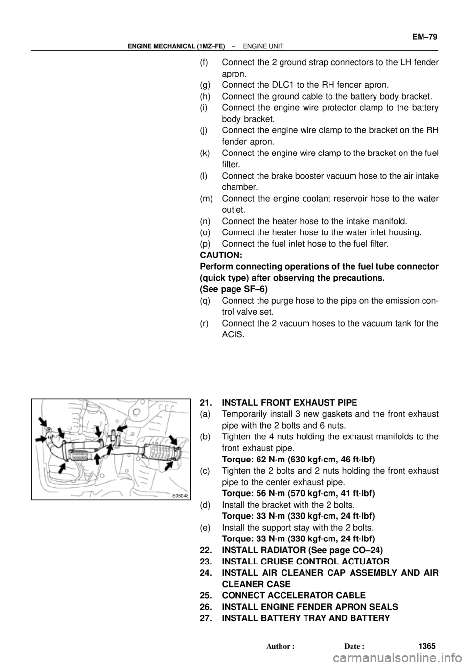
21. INSTALL FRONT EXHAUST PIPE
(a) Temporarily install 3 new gaskets and the front exhaust
pipe with the 2 bolts and 6 nuts.
(b) Tighten the 4 nuts holding the exhaust manifolds to the
front exhaust pipe.
Torque: 62 N´m (630 kgf´cm, 46 ft´lbf)
(c) Tighten the 2 bolts and 2 nuts holding the front exhaust
pipe to the center exhaust pipe.
Torque: 56 N´m (570 kgf´cm, 41 ft´lbf)
(d) Install the bracket with the 2 bolts.
Torque: 33 N´m (330 kgf´cm, 24 ft´lbf)
(e) Install the support stay with the 2 bolts.
Torque: 33 N´m (330 kgf´cm, 24 ft´lbf)
22. INSTALL RADIATOR (See page CO±24)
23. INSTALL CRUISE CONTROL ACTUATOR
24. INSTALL AIR CLEANER CAP ASSEMBLY AND AIR
CLEANER CASE
25. CONNECT ACCELERATOR CABLE
26. INSTALL ENGINE FENDER APRON SEALS
27. INSTALL BATTERY TRAY AND BATTERY
Page 3986 of 4770
SS0AJ±03
SS±24
± SERVICE SPECIFICATIONSCOOLING (5S±FE)
187 Author�: Date�:
TORQUE SPECIFICATION
Part tightenedN´mkgf´cmft´lbf
Cylinder block x Drain plug2525018
Water pump x Water pump cover, Cylinder block8.89078 in.´lbf
Water bypass pipe x Water pump cover9.39582 in.´lbf
Generator drive belt adjusting bar x Cylinder block2222416
Water inlet x Water pump cover8.89078 in.´lbf
Oil cooler x Radiator lower tank8.38574 in.´lbf
Oil cooler pipe x Oil cooler14.715011
Upper radiator support x Body12.81309
Electric cooling fan x Radiator5.05044 in.´lbf