Page 3019 of 4770
F00073
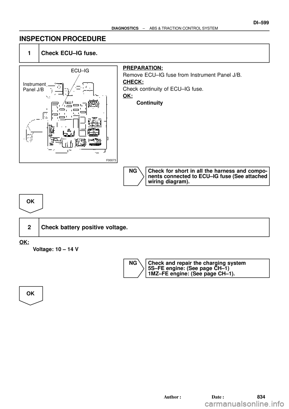
ECU±IGECU±IG
Instrument
Panel J/BECU±IG
± DIAGNOSTICSABS & TRACTION CONTROL SYSTEM
DI±599
834 Author�: Date�:
INSPECTION PROCEDURE
1 Check ECU±IG fuse.
PREPARATION:
Remove ECU±IG fuse from Instrument Panel J/B.
CHECK:
Check continuity of ECU±IG fuse.
OK:
Continuity
NG Check for short in all the harness and compo-
nents connected to ECU±IG fuse (See attached
wiring diagram).
OK
2 Check battery positive voltage.
OK:
Voltage: 10 ± 14 V
NG Check and repair the charging system
5S±FE engine: (See page CH±1)
1MZ±FE engine: (See page CH±1).
OK
Page 3021 of 4770

± DIAGNOSTICSABS & TRACTION CONTROL SYSTEM
DI±601
836 Author�: Date�:
DTC 43 ABS Control System Malfunction
CIRCUIT DESCRIPTION
DTC No.DTC Detecting ConditionTrouble Area
43
Detection of any conditions from 1. through 8.:
1. During TRAC is in non±operation and DTC of ABS is
output, but TRAC is not during initial lamp checking,
terminal WA of ECU is ON and engine speed is 500 rpm
or more , which continues for 1 sec. or more.
2. Solenoid relay circuit is open or short.
3. Motor relay circuit is open or short.
4. ABS solenoid circuit is open or short.
5. TRAC solenoid circuit is open or short.
6. Speed sensor is under malfunction condition.
7. IG power source is down or raised.
8. Pump motor is locked.
�ABS control system
INSPECTION PROCEDURE
1 Check the DTC for the ABS (See page DI±574).
*1 Repair ABS control system according to the
code output.
*2
Check for ECU connected to malfunction indicator lamp.
*1: Output NG code
*2: Malfunction indicator lamp remains ON.
DI04O±04
Page 3022 of 4770

F00062
ECMABS & TRAC ECU
NEONEO
E8
A16BR±W15 ECMABS & TRAC ECU
NEONEOA16BR±W15 ECMABS & TRAC ECU
NEONEOA16BR±W15 ECMABS & TRAC ECU
NEONEOA16BR±W15
ECMABS & TRAC ECU
NEONEO
A16BR±W15
16
DI±602
± DIAGNOSTICSABS & TRACTION CONTROL SYSTEM
837 Author�: Date�:
DTC 44 NE Signal Circuit
CIRCUIT DESCRIPTION
The ABS & TRAC ECU receives engine speed signals (NE signals) from the ECM.
DTC No.DTC Detecting ConditionTrouble Area
44
Condition 1. or 2. is detected:
1. TRAC is in operation and engine speed is 0 rpm contin-
ues for 2.4 sec. or more.
2. TRAC is in non±operation, sift lever is not in P or N posi-
tion, both the front right and left wheels' speed is 30
km/h (19 mph) or more, engine speed is 0 rpm and does
not have communication malfunction, and malfunction
information of engine system is OFF.
�NEO circuit
�ECM
�ECU
WIRING DIAGRAM
INSPECTION PROCEDURE
1 Check for open and short circuit in harness and connector between terminal
NEO of ABS & TRAC ECU and terminal NEO of ECM (See page IN±31).
NG Repair or replace harness or connector.
OK
DI04P±04
Page 3023 of 4770
F00061
NEO (+) (±) ON
F00011
(Reference)
3 ± 6 V
Below 1 V
3 ms. 3 ms. (Reference)
3 ± 6 V
Below 1 V
3 ms. 3 ms.(Reference)
3 ± 6 V
Below 1 V
3 ms. 3 ms.
± DIAGNOSTICSABS & TRACTION CONTROL SYSTEM
DI±603
838 Author�: Date�:
2 Check voltage between terminal NEO of ABS & TRAC ECU and body ground.
PREPARATION:
(a) Remove ABS & TRAC ECU with connectors still con-
nected.
(b) Turn ignition switch ON.
CHECK:
Measure voltage between terminal NEO of ABS & TRAC ECU
and body ground for the engine conditions below.
OK:
Engine conditionVoltage
OFF (IG ON)3 ± 6 V or below 1 V
ON (Idling)2 ± 3 V (Pulse)
NG Check and replace ABS & TRAC ECU or ECM.
OK
If the same code is still output after the DTC is deleted, check the contact condition of each con-
nection.
Page 3026 of 4770
F03413
ALTEngine Room R/B No. 3
2ABS & TRAC
Motor Relay
A8ABS & TRAC ActuatorABS
4
W±R
MTR+ GR±L
14 24
MR A15
13
F5
F4
B±GFL
Block
MAIN
Battery
EA 1 B±G
333
1
2
3
A8A8
1 23
W±BA15
A15 GR±R
R±W 1ABS & TRAC ECU
1 DI±606
± DIAGNOSTICSABS & TRACTION CONTROL SYSTEM
841 Author�: Date�:
DTC 51 ABS Pump Motor Lock
CIRCUIT DESCRIPTION
DTC No.DTC Detecting ConditionTrouble Area
51
In the midst of initial check, after the current flows to the
motor for 3 sec. and motor relay is turned OFF , then
within 0.66 sec., the condition that the motor relay
monitor is OFF continues for 0.24 sec. or more.
�ABS pump motor
Fail safe function:
If any trouble occurs in the ABS & TRAC pump motor, the ECU cuts off current to the ABS & TRAC solenoid
relay and prohibits ABS control and TRAC control.
WIRING DIAGRAM
DI4KX±01
Page 3028 of 4770

F00063
ECMABS & TRAC ECU
EFI+
EFI±
TRC+
TRC±EFI+
EFI±
TRC+
TRC±
E7
E7
E7
E7A16
A16
A16
A1614 6
14
13
5W
B
L ECMABS & TRAC ECU
EFI+
EFI±
TRC+
TRC±EFI+
EFI±
TRC+
TRC±E7
E7
E7
E7A16
A16
A16
A16
21
206
14
13
5
W
B
L ECMABS & TRAC ECU
EFI+
EFI±
TRC+
TRC±EFI+
EFI±
TRC+
TRC±E7
E7
E7
E7A16
A16
A16
A166
14
13
5W
B
L
ECMABS & TRAC ECU
EFI+
EFI±
TRC+
TRC±EFI+
EFI±
TRC+
TRC±
E7
E7
E7
E7A16
A16
A16
A166
14
13
5W
B
LG
L
13
DI±608
± DIAGNOSTICSABS & TRACTION CONTROL SYSTEM
843 Author�: Date�:
DTC 53 ECM Communication Circuit Malfunction
CIRCUIT DESCRIPTION
This circuit is used to send TRAC control information from the ABS & TRAC ECU to the ECM (TRC+, TRC±),
and engine control information from the ECM to the ABS & TRAC ECU (EFI+, EFI±).
DTC No.DTC Detecting ConditionTrouble Area
53ECM communication data malfunction is detected.
�TRC+ or TRC± circuit
�EFI+ or EFI± circuit
�ECM
�ECU
WIRING DIAGRAM
INSPECTION PROCEDURE
1 Check for open and short circuit in harness and connector between terminals
EFI+, EFI±, TRC+, TRC± of ABS & TRAC ECU and ECM (See page IN±31).
NG Repair or replace harness or connector.
OK
Check and replace ECM or ABS & TRAC ECU.
DI04S±04
Page 3029 of 4770
± DIAGNOSTICSABS & TRACTION CONTROL SYSTEM
DI±609
844 Author�: Date�:
DTC 61 Engine Control System Malfunction
CIRCUIT DESCRIPTION
If any trouble occurs in the engine control system, the ECU prohibits TRAC control.
DTC No.DTC Detection ConditionTrouble Area
61
Conditions 1. and 2. are detected:
1. ECM communication is normal, malfunction information
of engine system is ON, and engine speed is 500 rpm or
more , which continues for 0.48 sec. or more, and TRAC
operation start condition is concluded.
2. ECM communication is normal, malfunction information
of engine system is ON, engine speed is 500 rpm and
more which continues for 1 sec. or more, and the engine
system memorizes DTC.
�Engine control system
INSPECTION PROCEDURE
1 Check the DTC for the engine (See page DI±197).
*1 Repair engine control system according to the
code output.
*2
Check for ECU connected to malfunction indicator light.
*1: Output NG code
*2: Malfunction indicator light remains ON.
DI04T±04
Page 3031 of 4770
± DIAGNOSTICSABS & TRACTION CONTROL SYSTEM
DI±611
846 Author�: Date�:
4 Check battery positive voltage.
CHECK:
Check the battery positive voltage.
OK:
10 ± 14 V
NG Check and repair the charging system
5S±FE engine: (See page CH±1)
1MZ±FE engine: (See page CH±1).
OK
5 Check ABS warning light.
PREPARATION:
(a) Disconnect the connector from the ABS & TRAC ECU.
(b) Turn the ignition switch ON.
CHECK:
Check the ABS warning light goes off.
OK Check and replace ABS & TRAC ECU.
NG
Check for short circuit in harness and connector between ABS warning light, DLC1, DLC2, and
ABS & TRAC ECU (See page IN±31)
 (±) ON
F00011
(Reference)
3 ± 6 V
Below 1 V
3 ms. 3 ms. (Reference)
3 ± 6 V
Below 1 V
3 ms. 3 ms.(Reference)
3 ± 6 V
Below 1 V
3 ms. 3 ms.
± DIAGNOSTICSABS & TRACTION CONTROL SYSTE")