Page 2950 of 4770
(±)
(+) (±)1 2 3
4 5 6 Continuity
DI±530
± DIAGNOSTICSANTI±LOCK BRAKE SYSTEM (DENSO Made)
765 Author�: Date")
F00043
1 2 3
4 5 6
1 2 3
4 5 6
1 2 3
4
65 Open
Continuity
Continuity
Continuity
Open
(+)(±)
(+) (±)1 2 3
4 5 6 Continuity
DI±530
± DIAGNOSTICSANTI±LOCK BRAKE SYSTEM (DENSO Made)
765 Author�: Date�:
2 Check ABS solenoid relay.
PREPARATION:
Remove ABS solenoid relay from Engine Room R/B No. 3.
CHECK:
Check continuity between each terminal of ABS solenoid relay.
OK:
Terminals 4 and 6Continuity (Reference value 80 W)
Terminals 2 and 3Continuity
Terminals 1 and 3Open
CHECK:
(a) Apply battery positive voltage between terminals 4 and 6.
(b) Check continuity between each terminal of ABS solenoid
relay.
OK:
Terminals 2 and 3Open
Terminals 1 and 3Continuity
CHECK:
Connect the � test lead to terminal 5 and the � lead to terminal
3. Check continuity between the terminals.
OK:
Continuity
If there is no continuity, connect the � test lead to terminal 5
and the � lead to terminal 3. Recheck continuity between ter-
minals.
NG Replace ABS solenoid relay.
OK
Check for open circuit in harness and connector between DLC1, ABS solenoid relay and body
ground (See page IN±31).
Page 2954 of 4770
F00172
J/C
EC BRA
ABR
3
16 DLC1
Ts E
1
R±Y
II38
R±Y
A198
TsABS ECU
J22: (1MZ±FE)
J23: (5S±FE)
J/C
BRA
ABR
3
16 DLC1
Ts E
1
R±Y
II38
R±Y
A198
TsABS ECU
J22: (1MZ±FE)
J23: (5S±FE)
AB0119S08096
F00446DLC1 DLC1
DLC1
DLC1DLC1
Ts
DLC1 E1
ON
DI±534
± DIAGNOSTICSANTI±LOCK BRAKE SYSTEM (DENSO Made)
769 Author�: Date�:
Ts Terminal Circuit
CIRCUIT DESCRIPTION
The sensor check circuit detects abnormalities in the speed sensor signal which cannot be detected with
the DTC check.
Connecting terminals Ts and E
1 of the DLC1 in the engine compartment starts the check.
WIRING DIAGRAM
INSPECTION PROCEDURE
1 Check voltage between terminals Ts and E1 of DLC1.
CHECK:
(a) Turn the ignition switch ON.
(b) Measure voltage between terminals Ts and E
1 of DLC1.
OK:
Voltage: 10 ± 14 V
OK If ABS warning light does not blink even after Ts
and E
1 are connected, the ECU may be defec-
tive.
NG
DI03S±03
Page 2960 of 4770

775 Author�: Date�:
(d) Clear the DTC.
(1) Using SST, connect terminals Tc and E")
BR3890
F02201
DLC1
TsTc E1
BR3904
0.13 sec. 0.12 sec.
ON
OFF DI±540
± DIAGNOSTICSANTI±LOCK BRAKE SYSTEM (BOSCH Made)
775 Author�: Date�:
(d) Clear the DTC.
(1) Using SST, connect terminals Tc and E
1 of DLC2 or
DLC1.
SST 09843 ± 18020
(2) Turn the ignition switch ON.
(3) Clear the DTC stored in ECU by depressing the
brake pedal 8 or more times within 3 seconds.
(4) Check that the warning light shows the normal
code.
(5) Remove the SST from the terminals of DLC2 or
DLC1.
SST 09843 ± 18020
HINT:
Cancellation cannot be done by removing the battery cable or
ECU±B fuse.
2. SPEED SENSOR SIGNAL
(a) Check the speed sensor signal.
(1) When the ignition switch is turned ON, check that
the ABS warning light goes on for 2 seconds.
(2) Turn the ignition switch OFF.
(3) Using SST, connect terminals Ts and E
1 of DLC1.
SST 09843 ± 18020
(4) Start the engine.
(5) Check that the ABS warning light blinks.
HINT:
If the ABS warning light does not blink, inspect the ABS warning
light circuit (See page DI±565).
(6) Drive vehicle straight forward.
HINT:
Drive vehicle at 45 ± 55 km/h (28 ± 34 mph) for several seconds.
If the brake is applied during the check, the check routine must
be started again.
(7) Stop the vehicle.
(8) Turn the ignition switch OFF.
(9) Disconnect the SST from terminals Ts and E
1 and,
connect the SST to terminals Tc and E
1 of DLC1.
SST 09843 ± 18020
(10) Turn the ignition switch ON.
(11) Read the number of blinks of the ABS warning light.
Page 2966 of 4770

DI040±08
F03949
Actuator Assembly
BatteryActuator Assembly
MAINB±GF4 1 ALT
FL
Block 1F5 B±G3
ABS
12 3
Engine
Room R/B
No.3L
L
18
A6
+B+BA6
Valve Relay
Motor Relay17
A6 16 GND2
W±BEA
W±B
W±B 19
A6GND1 ECU DI±546
± DIAGNOSTICSANTI±LOCK BRAKE SYSTEM (BOSCH Made)
781 Author�: Date�:
CIRCUIT INSPECTION
DTC 11 ABS Solenoid Valve Relay Circuit
CIRCUIT DESCRIPTION
This relay supplies power to each ABS solenoid. After the ignition switch is turned ON, if the initial check is
OK, the relay goes on.
DTC No.DTC Detecting ConditionTrouble Area
11
Detection of any conditions from 1. through 3.:
1. 3 or more solenoid valves are shown faulty in response
and simultaneously valve supply voltage is detected
faulty.
2. Solenoid valve relay will not be switched OFF.
3. Valve relay is frozen in spite of its high valve relay sup-
ply voltage.
�ABS solenoid valve relay
�Valve supply voltage
�ECU
Fail safe function:
If trouble occurs in the ABS solenoid valve relay circuit, the ECU cuts off current to the ABS solenoid valve
relay and prohibits ABS control.
WIRING DIAGRAM
Page 2968 of 4770

F03949
Actuator Assembly
BatteryActuator Assembly
MAINB±GF4 1 ALT
FL
Block 1F5 B±G3
ABS
12 3L
L
18
A6
+B+BA6
Valve Relay
Motor Relay17
A6 16 GND2
W±BEA
W±B
W±B 19
A6GND1 ECU Engine
Room R/B
No.3 DI±548
± DIAGNOSTICSANTI±LOCK BRAKE SYSTEM (BOSCH Made)
783 Author�: Date�:
DTC 13 Pump Motor Circuit
CIRCUIT DESCRIPTION
The ABS motor relay supplies power to the ABS pump motor. While the ABS is activated, the ECU switches
the ABS motor relay ON and operates the ABS pump motor.
DTC No.DTC Detecting ConditionTrouble Area
13
Detection of any conditions from (1) through (3):
1. After actuation of the motor relay, pump motor voltage
will not be supplied within 0.4 sec.
2. Pump motor voltage is at a high level, motor relay will
not actuate for 2.5 sec. or more.
3. Pump motor voltage keeps low level for longer than 0.4
sec. and the pump repeats activating for 7 sec. 3 times
maximally. since the last activation, the pump motor has
been gone dead because of short circuit.
�ABS motor relay
�Pump motor voltage
�Pump motor lead disconnected
�ECU
Fail safe function:
If trouble occurs in the ABS motor relay circuit, the ECU cuts off current to the ABS solenoid relay and prohib-
its ABS control.
WIRING DIAGRAM
DI041±08
Page 2970 of 4770
F03949
Actuator Assembly
BatteryActuator Assembly
MAINB±GF4 1 ALT
FL
Block 1F5 B±G3
ABS
12 3
Engine
Room R/B
No.3L
L
18
A6
+B+BA6
Valve Relay
Motor Relay17
A6 16 GND2
W±BEA
W±B
W±B 19
A6GND1 ECU DI±550
± DIAGNOSTICSANTI±LOCK BRAKE SYSTEM (BOSCH Made)
785 Author�: Date�:
DTC 21, 22, 23, 24 ABS Solenoid Valve Circuit
CIRCUIT DESCRIPTION
This solenoid goes on when signals are received from the ECU and controls the pressure acting on the wheel
cylinders thus controlling the braking force.
DTC No.DTC Detecting ConditionTrouble Area
21, 22, 23, 24Solenoid valve signal does not match to the check result.�Each solenoid valve
Fail safe function:
If trouble occurs in the actuator solenoid valve circuit, the ECU cuts off current to the ABS solenoid valve
relay and prohibits ABS control.
WIRING DIAGRAM
DI042±08
Page 2978 of 4770

F03950
Actuator Assembly LB±R
IG1Actuator Assembly LB±R
IG1Actuator Assembly LB±R
IG1Actuator Assembly LB±R
IG1Actuator Assembly L
IG1
BatteryMAINB±G1
F4 ALTFL
Block 1F5 B±G3
ABS
12
Engine
Room R/B
No.3 3L
18
A617
A6
+B+B
Valve Relay
Motor Relay
GND2
A6
1615
A65
B±R
IK3B±R
C
C
J12 J/C
ECU
GND119
A6W±B
W±B
W±B
EAECU±IG
Instrument
Panel J/B 1J
9 DI±558
± DIAGNOSTICSANTI±LOCK BRAKE SYSTEM (BOSCH Made)
793 Author�: Date�:
DTC 41 Power Source Circuit
CIRCUIT DESCRIPTION
This is the power source for the ECU, hence the actuators.
DTC No.DTC Detecting ConditionTrouble Area
41
Vehicle speed at about 6 km/h (4 mph), low battery voltage
is less than 9.4 V at the time of non±operation of ABS
control or less than 8.8 V at the time of operation of ABS
control, and high battery voltage is more than 17.4 V.�Battery
�Charging system
�Power source circuit
�ECU
Fail safe function:
If trouble occurs in the power source circuit, the ECU cuts off current to the ABS solenoid valve relay and
prohibits ABS control.
WIRING DIAGRAM
DI045±08
Page 2979 of 4770
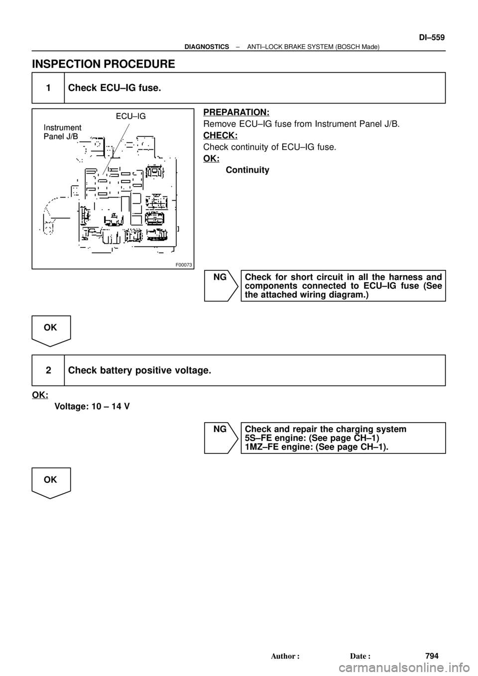
F00073
ECU±IG
Instrument
Panel J/BECU±IG
Instrument
Panel J/BECU±IG
Instrument
Panel J/B
± DIAGNOSTICSANTI±LOCK BRAKE SYSTEM (BOSCH Made)
DI±559
794 Author�: Date�:
INSPECTION PROCEDURE
1 Check ECU±IG fuse.
PREPARATION:
Remove ECU±IG fuse from Instrument Panel J/B.
CHECK:
Check continuity of ECU±IG fuse.
OK:
Continuity
NG Check for short circuit in all the harness and
components connected to ECU±IG fuse (See
the attached wiring diagram.)
OK
2 Check battery positive voltage.
OK:
Voltage: 10 ± 14 V
NG Check and repair the charging system
5S±FE engine: (See page CH±1)
1MZ±FE engine: (See page CH±1).
OK

J23: (5S±FE)
J/C
BRA
ABR
3
16 DLC1
Ts E
1
R±Y
II38
R±Y
A198
TsABS ECU
J22: (1MZ±FE)
J23: (5S±FE)
AB0119S08096
F")