Page 2924 of 4770
 (±)
Engine Room
R/B No. 3
3
45 6 12 (+) (±)
Engine Room
R/B No. 3
3
45 6 12 (+) (±)
Engine Room
R/B No. 3
3
45 612 (+) (±)
Engine Room
R/B No. 3
3
45 6
F07153
3
4
ABS
Actuator
AB")
F00048
12 (+) (±)
Engine Room
R/B No. 3
3
45 6 12 (+) (±)
Engine Room
R/B No. 3
3
45 6 12 (+) (±)
Engine Room
R/B No. 3
3
45 612 (+) (±)
Engine Room
R/B No. 3
3
45 6
F07153
3
4
ABS
Actuator
ABS
Solenoid
Relay
A4
A18
ECUA5
1234
56781
5 2
6 3
7 4
8
SFRH
SFRR
SRLR
SRLH
SFLH
SFLR
SRRH
SRRR
DI±504
± DIAGNOSTICSANTI±LOCK BRAKE SYSTEM (DENSO Made)
739 Author�: Date�:
INSPECTION PROCEDURE
1 Check voltage between terminals 1 and 2 of Engine Room R/B No. 3 (for ABS so-
lenoid relay).
PREPARATION:
Remove ABS solenoid relay from Engine Room R/B No. 3.
CHECK:
Measure the voltage between terminals 1 and 2 of Engine
Room R/B No. 3 (for ABS solenoid relay).
OK:
Voltage: 10 ± 14 V
NG Check and repair harness or connector.
OK
2 Check continuity between terminal 3 of ABS solenoid relay and terminal SRLR,
SRLH, SRRR, SRRH, SFLR, SFLH, SFRR or SFRH of ABS ECU.
CHECK:
Check continuity between terminal 3 of Engine Room R/B No.3
(for ABS solenoid relay) and terminal SRLR, SRLH, SRRR,
SRRH, SFLR, SRLH, SFRR or SFRH of ABS ECU.
OK:
Continuity
HINT:
Resistance of each solenoid coil
SRLR, SRRR, SFLR, SFRR: 4.3 W
SRLH, SRRH, SFLH, SFRH: 8.8 W
NG Repair or replace harness or ABS actuator.
OK
Page 2928 of 4770
F07146
B±G
Fusible
Link
Block
F5 1
F4
1
FL
Main B±G
Battery3
3ABSABS Motor
Relay
2 13
43
3
Engine Room R/B No.3GR±R GR±R1
IK126
A19 R+ABS ECU
GR±L1
A18 MR
W±R2
A4
A41
W±B
EAABS Actuator
3
A4R±W10
A18 MT ALT DI±508
± DIAGNOSTICSANTI±LOCK BRAKE SYSTEM (DENSO Made)
743 Author�: Date�:
WIRING DIAGRAM
Page 2929 of 4770
 (±)
Engine Room
R/B No. 3
2
34 1 (+) (±)
Engine Room
R/B No. 32
34 1 (+) (±)
Engine Room
R/B No. 32
34
1 (+) (±)
Engine Room
R/B No. 3
2
34
F07154
3 3
ECU ECU
ECU
ABS
Motor
Relay2")
F00049
1 (+) (±)
Engine Room
R/B No. 3
2
34 1 (+) (±)
Engine Room
R/B No. 32
34 1 (+) (±)
Engine Room
R/B No. 32
34
1 (+) (±)
Engine Room
R/B No. 3
2
34
F07154
3 3
ECU ECU
ECU
ABS
Motor
Relay2
A4
A4
A18
MT
2
2
ECU
ABS
Actuator
± DIAGNOSTICSANTI±LOCK BRAKE SYSTEM (DENSO Made)
DI±509
744 Author�: Date�:
INSPECTION PROCEDURE
1 Check voltage between terminal 1 of Engine Room R/B No. 3 (for ABS motor
relay) and body ground.
PREPARATION:
Remove ABS motor relay from Engine Room R/B No. 3.
CHECK:
Measure voltage between terminal 1 of Engine Room R/B No.
3 (for ABS motor relay) and body ground.
OK:
Voltage: 10 ± 14 V
NG Check and repair harness or connector.
OK
2 Check continuity between terminal 2 of ABS motor relay and terminal MT of ABS
ECU.
CHECK:
Check continuity between terminal 2 of Engine Room R/B No.3
(for ABS motor relay) and terminal MT of ABS ECU.
OK:
Continuity
HINT:
There is a resistance of 4 ~ 6 W between terminals A4 ± 2 and
A4 ± 3 of ABS actuator.
NG Repair or replace harness or ABS actuator.
OK
Page 2932 of 4770
F07147
ABS Solenoid RelayGR±R1
IK1
GR±RABS ECU
26
A19R+
34
56
33
3
3 1
2 DLC1Engine Room
R/B No.3
GR
7
2ABS
1
3
W±L
B±G
Fusible Link Block
1
F5 F41
B±G
FL Main
Battery ALT
EAW±B4
A4A18 SR
ABS
Actuator
1
A5
A55
A53
7
A5
A5
A5
A5
A54
8
2
6R±B
W±R11
IK2
IK212R±B
W±R2
A19
A191
A18
A18
A18
A18
A19
A19 L±B
W±L
W±R
R±G
G±Y
LG±B13
IK2
IK255
6
11
12
15
14SFRH
SFRR
SFLH
SFLR
SRRH
SRRR
SRLH
SRLR 3
G±Y
LG±B DI±512
± DIAGNOSTICSANTI±LOCK BRAKE SYSTEM (DENSO Made)
747 Author�: Date�:
WIRING DIAGRAM
Page 2941 of 4770
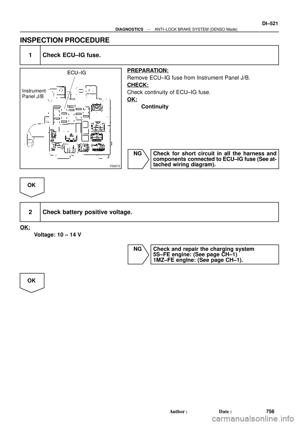
F00073
ECU±IGECU±IG
Instrument
Panel J/BECU±IG
± DIAGNOSTICSANTI±LOCK BRAKE SYSTEM (DENSO Made)
DI±521
756 Author�: Date�:
INSPECTION PROCEDURE
1 Check ECU±IG fuse.
PREPARATION:
Remove ECU±IG fuse from Instrument Panel J/B.
CHECK:
Check continuity of ECU±IG fuse.
OK:
Continuity
NG Check for short circuit in all the harness and
components connected to ECU±IG fuse (See at-
tached wiring diagram).
OK
2 Check battery positive voltage.
OK:
Voltage: 10 ± 14 V
NG Check and repair the charging system
5S±FE engine: (See page CH±1)
1MZ±FE engIne: (See page CH±1).
OK
Page 2945 of 4770
F07146
B±G
Fusible
Link
Block
F5 1
F4
1
FL
Main B±G
Battery3
3ABSABS Motor
Relay
2 13
43
3
Engine Room R/B No.3GR±R GR±R1
IK126
A19 R+ABS ECU
GR±L1
A18 MR
W±R2
A4
A41
W±B
EAABS Actuator
3
A4R±W10
A18 MT ALT
± DIAGNOSTICSANTI±LOCK BRAKE SYSTEM (DENSO Made)
DI±525
760 Author�: Date�:
DTC 51 ABS Pump Motor Lock
CIRCUIT DESCRIPTION
DTC No.DTC Detecting ConditionTrouble Area
51ABS actuator pump motor is not operating normally.�ABS pump motor
Fail safe function:
If trouble occurs in the ABS pump motor, the ECU cuts off current to the ABS solenoid relay and prohibits
ABS control.
WIRING DIAGRAM
DI4KW±01
Page 2948 of 4770
DI±528
± DIAGNOSTICSANTI±LOCK BRAKE SYSTEM (DENSO Made)
763 Author�: Date�:
4 Check battery positive voltage.
CHECK:
Check the battery positive voltage.
OK:
10 ± 14 V
NG Check and repair the charging system
5S±FE engine: (See page CH±1)
1MZ±FE engine: (See page CH±1).
OK
5 Check ABS warning light.
PREPARATION:
(a) Disconnect the connector from the ABS ECU.
(b) Turn the ignition switch ON.
CHECK:
Check the ABS warning light goes off.
OK Check and replace ABS ECU.
NG
Check for short circuit in harness and connector between ABS warning light, DLC1, DLC2, and
ABS ECU (See page IN±31).
Page 2949 of 4770

F07217
Engine Room R/B No. 3
ABS Solenoid Relay
3
ABS
Actuator
A4 1
2
5 BatteryGAUGE Instrument Panel J/B
J/C
J4
D
ABS ECU 33 3 3
EA34 6
ABS ECUD
IK28
R±L
II3 4
DLC1 R±L
G±B
II3 5 Short
Pin
W±B
ABS ECU W±L
G±B
C
CC R±L
R±L 1D2
7
4
R±L
A19WA IG3 12
11 G±B 4
G±B C10
C10
J/C
J29ABS Warning
Light
23
22 R±L
± DIAGNOSTICSANTI±LOCK BRAKE SYSTEM (DENSO Made)
DI±529
764 Author�: Date�:
ABS Warning Light Circuit
CIRCUIT DESCRIPTION
If the ECU detects trouble, it lights the ABS warning light while at the same time prohibiting ABS control. At
this time, the ECU records a DTC in memory.
After removing the short pin of the DLC1, connect terminals Tc and E
1 of the DLC1 or DLC2 to make the
ABS warning light blink and output the DTC.
WIRING DIAGRAM
INSPECTION PROCEDURE
Troubleshooting in accordance with the chart below for each trouble symptom.
ABS warning light does not light upGo to step 1
ABS warning light remains onGo to step 3
1 Check ABS warning light.
See combination meter troubleshooting on page BE±2.
NG Repair bulb or combination meter assembly.
OK
DI03Q±03