Page 3032 of 4770

F00168
BatteryABS & TRAC
Solenoid Relay Engine Room R/B No. 3
3ABS & TRAC
ECU
A8 1
R±L
C 5 4
IG3 IK2 6
J/C C10
EA4ABS Warning Light 8
12 II3
G±B23 2
22 ABS & TRAC
Actuator
DLC1 Short
Pin
WA
J29 33 3 3
3
W±B4
ABS & TRAC
ECUR±L
4
R±L
II3 5
G±B
C C G±B R±LC107
ABS & TRAC ECU R±LR±L
J/C
D 1D
GAUGE Instrument Panel J/B
A16 J4 D
G±B4 W±L
2
DI±612
± DIAGNOSTICSABS & TRACTION CONTROL SYSTEM
847 Author�: Date�:
ABS Warning Light Circuit
CIRCUIT DESCRIPTION
If the ECU detects a trouble, it lights the ABS warning light while at the same time prohibiting ABS control.
At this time, the ECU records a DTC in memory.
Connect terminals Tc and E
1 of the DLC1 or DLC2 to make the ABS warning light blink and output the DTC.
WIRING DIAGRAM
INSPECTION PROCEDURE
Troubleshoot in accordance with the chart below for each trouble symptom.
ABS warning light does not light upGo to step 1
ABS warning light remains onGo to step 3
1 Check ABS warning light.
See combination meter troubleshooting on page BE±2.
NG Repair bulb or combination meter assembly.
OK
DI04V±04
Page 3033 of 4770
 (±)
(+) (±)1 2 3
4 5 6 Continuity
± DIAGNOSTICSABS & TRACTION CONTROL SYSTEM
DI±613
848 Author�: Date�:
2 C")
F00043
1 2 3
4 5 6
1 2 3
4 5 6
1 2 3
4 65 Open
Continuity
Continuity
Open Continuity
(+) (±)
(+) (±)1 2 3
4 5 6 Continuity
± DIAGNOSTICSABS & TRACTION CONTROL SYSTEM
DI±613
848 Author�: Date�:
2 Check ABS & TRAC solenoid relay.
PREPARATION:
Remove ABS & TRAC solenoid relay from Engine Room R/B
No. 3.
CHECK:
Check continuity between each terminal of ABS & TRAC sole-
noid relay.
OK:
Terminals 4 and 6Continuity (Reference value 80 W)
Terminals 2 and 3Continuity
Terminals 1 and 3Open
CHECK:
(a) Apply battery positive voltage between terminals 4 and 6.
(b) Check continuity between each terminal of ABS & TRAC
solenoid relay.
OK:
Terminals 2 and 3Open
Terminals 1 and 3Continuity
CHECK:
Connect the � test lead to terminal 5 and the � lead to terminal
3. Check continuity between the terminals.
OK:
Continuity
If there is no continuity, connect the � test lead to terminal 5
and the � lead to terminal 3. Recheck continuity between ter-
minals.
NG Replace ABS & TRAC solenoid relay.
OK
Check for open circuit in harness and connector between DLC1, ABS & TRAC solenoid relay and
body ground (See page IN±31).
Page 3035 of 4770
F00095
R±Y
3DLC1
J/CE1
ATs
J2211
II3 IK25
EC BRA15 BR
AR±Y
R±Y23 ABS & TRAC ECU
Ts
R±Y
3DLC1
J/CE1
ATs
J2211
II3 IK25
EC BRA15 BR
AR±Y
R±Y23 ABS & TRAC ECU
Ts
16
AB0119S08096
F00446
Ts
DLC1
E1
ON
± DIAGNOSTICSABS & TRACTION CONTROL SYSTEM
DI±615
850 Author�: Date�:
Ts Terminal Circuit
CIRCUIT DESCRIPTION
The sensor check circuit detects abnormalities in the speed sensor signal which cannot be detected with
the DTC check.
Connecting terminals Ts and E
1 of the DLC1 in the engine compartment starts the check.
WIRING DIAGRAM
INSPECTION PROCEDURE
1 Check voltage between terminals Ts and E1 of DLC1.
CHECK:
(a) Turn the ignition switch ON.
(b) Measure voltage between terminals Ts and E
1 of DLC1.
OK:
Voltage: 10 ± 14 V
OK If ABS warning light does not blink even after Ts
and E
1 are connected, the ECU may be defec-
tive.
NG
DI04X±04
Page 3055 of 4770
Detection ItemTrouble AreaSRS
Warning Light
B0135/73
(DI±743)�Short in P/T squib (LH) circuit�Seat belt prete")
± DIAGNOSTICSSUPPLEMENTAL RESTRAINT SYSTEM
DI±635
870 Author�: Date�:
DTC No.
(See Page)Detection ItemTrouble AreaSRS
Warning Light
B0135/73
(DI±743)�Short in P/T squib (LH) circuit�Seat belt pretensioner LH (squib)
�Airbag sensor assembly
�Wire harness
Blink
B0136/74
(DI±747)�Open in P/T squib (LH) circuit�Seat belt pretensioner LH (squib)
�Airbag sensor assembly
�Wire harness
Blink
B0137/71
(DI±750)�Short in P/T squib (LH) circuit
(to Ground)�Seat belt pretensioner LH (squib)
�Airbag sensor assembly
�Wire harness
Blink
B0138/72
(DI±753)�Short in P/T squib (LH) circuit
(to B+)�Seat belt pretensioner LH (squib)
�Airbag sensor assembly
�Wire harness
Blink
B1100/31
(DI±756)�Airbag sensor assembly malfunction�Airbag sensor assemblyON
B1140/32
(DI±758)�Side airbag sensor assembly (RH)
malfunction�Side airbag sensor assembly (RH)
�Wire harnessBlink
B1141/33
(DI±766)�Side airbag sensor assembly (LH)
malfunction�Side airbag sensor assembly (LH)
�Wire harnessBlink
B1156/B1157/
15
(DI±774)�Front airbag sensor (RH) malfunction�Front airbag sensor (RH)
�Wire harness
�Engine room main wire harness
ON
B1158/B1159/
16
(DI±782)�Front airbag sensor (LH) malfunction�Front airbag sensor (LH)
�Wire harness
ON
Nl�System normal±OFFNormal
(DI±787)�Voltage source drop�Battery
�Airbag sensor assemblyON
HINT:
�When the SRS warning light remains lit up and the DTC is the normal code, this means a voltage source
drops.
This malfunction is not stored in memory by the airbag sensor assembly and if the power source volt-
age returns to normal, the SRS warning light will automatically go out.
�When 2 or more codes are indicated, the codes will be displayed in numeral order starting from the
lowest numbered code.
�If a code not listed on the chart is displayed, the airbag sensor assembly is faulty.
Page 3194 of 4770
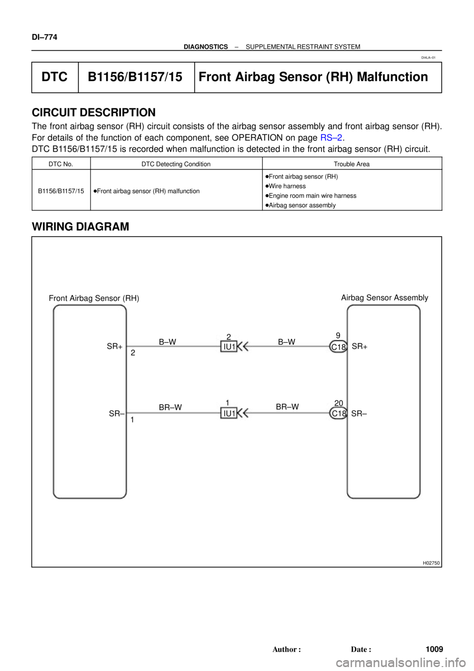
H02750
Airbag Sensor Assembly
Front Airbag Sensor (RH)
SR+
SR± C18
C189
20 B±W
BR±W IU12
1 B±W
BR±W 2
1 SR+
SR± IU1 DI±774
± DIAGNOSTICSSUPPLEMENTAL RESTRAINT SYSTEM
1009 Author�: Date�:
DTC B1156/B1157/15 Front Airbag Sensor (RH) Malfunction
CIRCUIT DESCRIPTION
The front airbag sensor (RH) circuit consists of the airbag sensor assembly and front airbag sensor (RH).
For details of the function of each component, see OPERATION on page RS±2.
DTC B1156/B1157/15 is recorded when malfunction is detected in the front airbag sensor (RH) circuit.
DTC No.DTC Detecting ConditionTrouble Area
B1156/B1157/15�Front airbag sensor (RH) malfunction
�Front airbag sensor (RH)
�Wire harness
�Engine room main wire harness
�Airbag sensor assembly
WIRING DIAGRAM
DI4LA±01
Page 3199 of 4770

(+)
SR+
(±)
SR±
ON
Engine Room Main
Wire Harness
u\"
H03354H06140H08258
Airbag
Sensor
Assembly Front Airbag
Sensor (RH)
(+)S")
H03354
H06141AB0119H08272
Airbag
Sensor
Assembly Front Airbag
Sensor (RH)
(+)
SR+
(±)
SR±
ON
Engine Room Main
Wire Harness
u"
H03354H06140H08258
Airbag
Sensor
Assembly Front Airbag
Sensor (RH)
(+)SR+
(±)SR± Engine Room Main
Wire Harness
± DIAGNOSTICSSUPPLEMENTAL RESTRAINT SYSTEM
DI±779
1014 Author�: Date�:
8 Check engine room main wire harness (to B+).
PREPARATION:
Disconnect the engine room main wire harness connector on
the airbag sensor assembly side.
CHECK:
(a) Turn ignition switch to ON.
(b) For the connector (on the RH front door wire harness
side) between the airbag sensor assembly and the en-
gine room main wire harness, measure the voltage be-
tween body ground and each of SR+ and SR±.
OK:
Voltage: Below 1 V
NG Repair or replace engine room main wire har-
ness.
OK
Repair or replace harness or connector between airbag sensor assembly and engine room main
wire harness.
9 Check engine room main wire harness (to ground).
PREPARATION:
Disconnect the engine room main wire harness connector on
the airbag sensor assembly side.
CHECK:
For the connector (on the engine room main wire harness side)
between the airbag sensor assembly and the engine room main
wire harness, measure the resistance between body ground
and each of SR+ and SR±.
OK:
Resistance: 1 MW or Higher
NG Repair or replace engine room main wire har-
ness.
OK
Repair or replace harness or connector between airbag sensor assembly and engine room main
wire harness.
Page 3200 of 4770
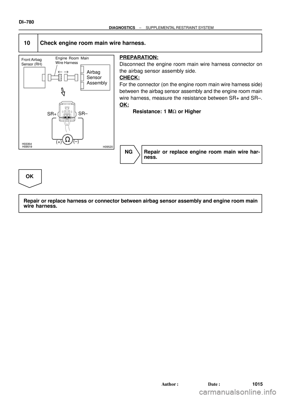
H03354H09519H09520
Airbag
Sensor
Assembly
Front Airbag
Sensor (RH)
(±) SR+SR±
Engine Room Main
Wire Harness
(+)
u "
DI±780
± DIAGNOSTICSSUPPLEMENTAL RESTRAINT SYSTEM
1015 Author�: Date�:
10 Check engine room main wire harness.
PREPARATION:
Disconnect the engine room main wire harness connector on
the airbag sensor assembly side.
CHECK:
For the connector (on the engine room main wire harness side)
between the airbag sensor assembly and the engine room main
wire harness, measure the resistance between SR+ and SR±.
OK:
Resistance: 1 MW or Higher
NG Repair or replace engine room main wire har-
ness.
OK
Repair or replace harness or connector between airbag sensor assembly and engine room main
wire harness.
Page 3201 of 4770
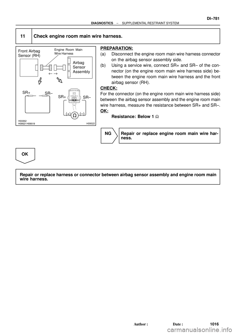
H03352H09519H09521H09522
Airbag
Sensor
Assembly Front Airbag
Sensor (RH)
(+) SR+
(±)SR±
Engine Room Main
Wire Harness
SR+
SR±
u "
± DIAGNOSTICSSUPPLEMENTAL RESTRAINT SYSTEM
DI±781
1016 Author�: Date�:
11 Check engine room main wire harness.
PREPARATION:
(a) Disconnect the engine room main wire harness connector
on the airbag sensor assembly side.
(b) Using a service wire, connect SR+ and SR± of the con-
nector (on the engine room main wire harness side) be-
tween the engine room main wire harness and the front
airbag sensor (RH).
CHECK:
For the connector (on the engine room main wire harness side)
between the airbag sensor assembly and the engine room main
wire harness, measure the resistance between SR+ and SR±.
OK:
Resistance: Below 1 W
NG Repair or replace engine room main wire har-
ness.
OK
Repair or replace harness or connector between airbag sensor assembly and engine room main
wire harness.