Page 3298 of 4770
Wiring ColorConditionSTD Voltage (V)
CMS e GND WLWB
Ignition switch ON
Main switch OFF10 ± 16 VCMS e GND
(C15")
DI±878
± DIAGNOSTICSCRUISE CONTROL SYSTEM
111 3 Author�: Date�:
Symbols (Terminals No.)Wiring ColorConditionSTD Voltage (V)
CMS e GND WLWB
Ignition switch ON
Main switch OFF10 ± 16 VCMS e GND
(C15±11 e C15±16)W±L e W±BIgnition switch ON
Main switch ONBelow 0.5 V
SPD e GND
(C15 12C15 16)V±W e W±B
Engine start
Car stoppage.Below 1.5 V or
4.7 ± 16 V
(C15±12 e C15±16)VW e WB
During driving (Pulse generated).3 ± 7 V
IDL e GND LRWB
Ignition switch ON
Throttle valve fully opened.10 ± 16 VIDL e GND
(C15±13 e C15±16)L±R e W±BIgnition switch ON
Throttle valve fully closed.Below 1.5 V
OD e GNDYBWB
During cruise control driving
OD switch ON.10 ± 16 VOD e GND
(C15±14 e C15±16)Y±B e W±BDuring cruise control driving
OD switch OFF (3rd driving)Below 1 V
MO e GND RGWB
During cruise control driving
ACC switch hold ON9 ± 15 VMO e GND
(C15±15 e C15±16)R±G e W±BDuring cruise control driving
COAST switch hold ONBelow 1 V
GND e Body Ground
(C15±16 e Body Ground)W±B e Body
GroundConstantBelow 1 V
Page 3315 of 4770
I00284
Cruise Control ECU
IDL 13
L±R *
2*1
ECM
IDL
*
1: 5S±FE Engine
*2: 1MZ±FE Engine E7 E8
C15
34
± DIAGNOSTICSCRUISE CONTROL SYSTEM
DI±895
1130 Author�: Date�:
DTC 51 Idle Signal Circuit
CIRCUIT DESCRIPTION
When the idle switch is turned ON, a signal is sent to the ECU. The ECU uses this signal to correct the dis-
crepancy between the throttle valve position and the actuator position sensor value to enable accurate
cruise control at the set speed. If the idle switch is malfunctioning, problem symptoms also occur in the en-
gine, so also inspect the engine.
DTC No.Detection ItemTrouble Area
51Short in idle signal circuit.
�Harness or connector between ECM and throttle position
sensor
�Throttle position sensor
�Harness or connector between cruise control ECU and ECM
�Cruise control ECU
WIRING DIAGRAM
DI08S±10
Page 3322 of 4770
AB0119
I00143
I00174
ON
O/D
(±) (+)
DI±902
± DIAGNOSTICSCRUISE CONTROL SYSTEM
1137 Author�: Date�:
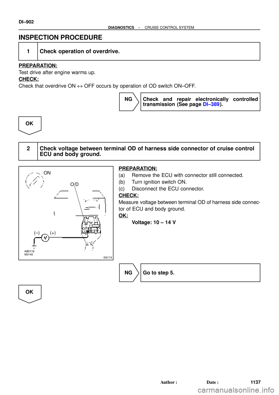
INSPECTION PROCEDURE
1 Check operation of overdrive.
PREPARATION:
Test drive after engine warms up.
CHECK:
Check that overdrive ON e OFF occurs by operation of OD switch ON±OFF.
NG Check and repair electronically controlled
transmission (See page DI±389).
OK
2 Check voltage between terminal OD of harness side connector of cruise control
ECU and body ground.
PREPARATION:
(a) Remove the ECU with connector still connected.
(b) Turn ignition switch ON.
(c) Disconnect the ECU connector.
CHECK:
Measure voltage between terminal OD of harness side connec-
tor of ECU and body ground.
OK:
Voltage: 10 ± 14 V
NG Go to step 5.
OK
Page 3323 of 4770
I00141
ECT
(±) (+)
± DIAGNOSTICSCRUISE CONTROL SYSTEM
DI±903
1138 Author�: Date�:
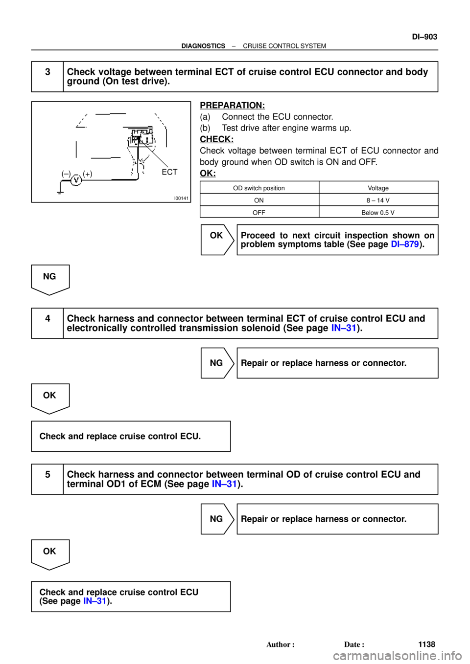
3 Check voltage between terminal ECT of cruise control ECU connector and body
ground (On test drive).
PREPARATION:
(a) Connect the ECU connector.
(b) Test drive after engine warms up.
CHECK:
Check voltage between terminal ECT of ECU connector and
body ground when OD switch is ON and OFF.
OK:
OD switch positionVoltage
ON8 ± 14 V
OFFBelow 0.5 V
OK Proceed to next circuit inspection shown on
problem symptoms table (See page DI±879).
NG
4 Check harness and connector between terminal ECT of cruise control ECU and
electronically controlled transmission solenoid (See page IN±31).
NG Repair or replace harness or connector.
OK
Check and replace cruise control ECU.
5 Check harness and connector between terminal OD of cruise control ECU and
terminal OD1 of ECM (See page IN±31).
NG Repair or replace harness or connector.
OK
Check and replace cruise control ECU
(See page IN±31).
Page 3325 of 4770
Input SignalIndicator Light
Blinking Pattern
Turn PNP switch
OFF (Shift to posi-
tions except D )LightON
OFFSW ON
SW OFF
± DIAGNOSTICSCRUISE CONTROL SYSTEM
DI±905
1140 Author�: Date�:
INSPECTION PROCEDURE
1 Check starter operation.
CHECK:
Check that the starter operates normally and that the engine starts.
NG Proceed to engine troubleshooting.
(5S±FE: See page ST±1)
(1MZ±FE: See page ST±1).
OK
2 Input signal check.
PREPARATION:
See input signal check on page DI±870.
CHECK:
Check the indicator light when shifting into positions except D.
OK:
The indicator light goes off when shifting into posi-
tions except D.
OK Proceed to next circuit inspection shown on
problem symptoms table (See page DI±879).
NG
Page 3327 of 4770

LightON
OFFSW ON
SW OFF
± DIAGNOSTICSCRUISE CONTROL SYSTEM
DI±907
1142 Author�: Date�:
Clutch Switch Circuit
C")
Input Signal
Indicator Light
Blinking Pattern
Clutch switch
OFF (Depress
clutch pedal)
LightON
OFFSW ON
SW OFF
± DIAGNOSTICSCRUISE CONTROL SYSTEM
DI±907
1142 Author�: Date�:
Clutch Switch Circuit
CIRCUIT DESCRIPTION
When the clutch pedal is depressed, the clutch switch sends a signal to the cruise control ECU. When the
signal is input to the cruise control ECU during cruise control driving, the cruise control ECU cancels cruise
control.
WIRING DIAGRAM
Refer to PNP switch circuit on page DI±904.
INSPECTION PROCEDURE
1 Check starter operation.
CHECK:
Check that the starter operates normally and that the engine starts.
NG Proceed to engine troubleshooting
(5S±FE: See page ST±1)
(1MZ±FE: See page ST±1).
OK
2 Input signal check.
PREPARATION:
See input signal check on page DI±870.
CHECK:
Check the indicator lights when clutch pedal is depressed.
OK:
The indicator light goes off when shifting into clutch
pedal is depressed.
OK Proceed to next circuit inspection shown on
problem symptoms table (See page DI±879).
NG
DI08W±04
Page 3339 of 4770
DI1KE±04
Vehicle Brought to Workshop
Customer Problem Analysis
Check and Clear DTC (Precheck)Items inside
are titles of pages in this manual,
with the page number in the bottom portion. See
the pages for detailed explanations.
Problem Symptom ConfirmationSymptom Simulation
Symptom
does not occur
Symptom
occurs
DTC Check
Circuit Inspection and part Inspection
DTC ChartMalfunction codeProblem Symptoms Table
Identification of Problem
Normal code
Repair
Confirmation Test
End
1
2
3
4
5
67
8
9
10
Step 2, 5 :Diagnostic steps permitting the use of the
TOYOTA hand±held tester or TOYOTA
break±out±box.
P. DI±920
P. DI±921
P. IN±21
P. DI±927 P. DI±921
P. DI±924
P. DI±928 ± DI±935
± DIAGNOSTICSENGINE IMMOBILISER SYSTEM
DI±919
1154 Author�: Date�:
ENGINE IMMOBILISER SYSTEM
HOW TO PROCEED WITH TROUBLESHOOTING
Troubleshooting in accordance with the procedure on the following pages.
Page 3340 of 4770
DI1KF±04
ENGINE IMMOBLISER Check SheetInspector 's
Name:
Customer 's Name
Date Vehicle
Brought InRegistration YearRegistration No.
Frame No.
Odometer Reading/ /
/ /
Date Problem First Occurred
Frequency Problem Occurs/ /
ContinuousIntermittent ( times a day)
DTC Check1st Time
2nd TimeNormal Code
Malfunction Code (Code )
Normal CodeMalfunction Code (Code )
Symptomskm
miles
Engine does not start.
Check ItemMalfunction
Indicator LampNormal
Remains ON Does not Light Up
Immobiliser is not set.
(Engine starts with key codes other than the registered key code.)
DI±920
± DIAGNOSTICSENGINE IMMOBILISER SYSTEM
1155 Author�: Date�:
CUSTOMER PROBLEM ANALYSIS CHECK


Items inside
are titles of pages in this manual,
with the page number in the bottom portion. See
the pages")
