Page 2786 of 4770

601 Author�: Date�:
DTC P1600 ECM BATT Malfunction
CIRC")
S05470
Battery FL
MAIN B±G
F4
F61 1
18
B Fusible
Link
BlockEngine Room J/B No.2
2A2JB±YECM
BATT EFI
E71 DI±366
± DIAGNOSTICSENGINE (1MZ±FE)
601 Author�: Date�:
DTC P1600 ECM BATT Malfunction
CIRCUIT DESCRIPTION
Battery positive voltage is supplied to terminal BATT of the ECM even when the ignition switch is OFF for
use by the DTC memory and air±fuel ratio adaptive control value memory, etc.
DTC No.DTC Detecting ConditionTrouble Area
P1600Open in back up power source circuit�Open in back up power source circuit
�ECM
HINT:
If DTC P1600 appear, the ECM does not store another DTC.
WIRING DIAGRAM
INSPECTION PROCEDURE
HINT:
Read freeze frame data using TOYOTA hand±held tester or OBD II scan tool. Because free frame records
the engine conditions when the malfunction is detected, when troubleshooting it is useful for determining
whether the vehicle was running or stopped, the engine warmed up or not, the air±fuel ratio lean or rich, etc.
at the time of the malfunction.
DI089±06
Page 2788 of 4770

603 Author�: Date�:
DTC P1780 Park/Neutral Position Switch Malfunction
CIRCUIT DESCRIPTION
The park/neutral position switch go on when the shift lever is in the")
DI±368
± DIAGNOSTICSENGINE (1MZ±FE)
603 Author�: Date�:
DTC P1780 Park/Neutral Position Switch Malfunction
CIRCUIT DESCRIPTION
The park/neutral position switch go on when the shift lever is in the N or P shift position. When it goes on
terminal NSW of the ECM is grounded to body ground via the starter relay, thus the terminal NSW voltage
becomes 0V. When the shift lever is in the D, 2, L or R position, the park/neutral position switch goes off,
so the voltage of ECM. Terminal NSW becomes battery voltage, the voltage of the ECM internal power
source. If the shift lever is moved from the N position to the D position, this signal is used for air±fuel ratio
correction and for idle speed control (estimated control), etc.
DTC No.DTC Detecting ConditionTrouble Area
2 or more switches are ON simultaneously for ºNº, º2º, ºLº and
ºRº positions
(2 trip detection logic)
Sh t i k/ t l iti it h i it
P1780When driving under conditions (a) and (b) for 30 sec. or more
the park/neutral position switch is ON (N position):
(2 trip detection logic)
(a) Vehicle speed: 70 km/h (44 mph) or more
(b) Engine speed: 1,500 � NE and 2,500 rpm�Short in park/neutral position switch circuit
�Park/neutral position switch
�ECM
HINT:
After confirming DTC P1780, use the TOYOTA hand±held tester to confirm the PNP switch signal from
ºCURRENT DATAº.
WIRING DIAGRAM
Refer to DTC P1780 on page DI±479.
INSPECTION PROCEDURE
Refer to DTC P1780 (Park/Neutral Position Switch Malfunction) on page DI±479.
HINT:
Read freeze frame data using TOYOTA hand±held tester or OBD II scan tool. because freeze frame records
the engine conditions when the malfunction is detected, when troubleshooting it is useful for determining
whether the vehicle was running or stopped, the engine warmed up or not, the air±fuel ratio lean or rich, etc.
at the time of the malfunction.
DI08A±06
Page 2796 of 4770
A00244
ON
BE6653
P20186
DI±376
± DIAGNOSTICSENGINE (1MZ±FE)
611 Author�: Date�:
INSPECTION PROCEDURE
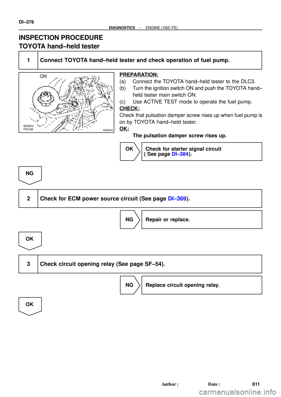
TOYOTA hand±held tester
1 Connect TOYOTA hand±held tester and check operation of fuel pump.
PREPARATION:
(a) Connect the TOYOTA hand±held tester to the DLC3.
(b) Turn the ignition switch ON and push the TOYOTA hand±
held tester main switch ON.
(c) Use ACTIVE TEST mode to operate the fuel pump.
CHECK:
Check that pulsation damper screw rises up when fuel pump is
on by TOYOTA hand±held tester.
OK:
The pulsation damper screw rises up.
OK Check for starter signal circuit
( See page DI±384).
NG
2 Check for ECM power source circuit (See page DI±369).
NG Repair or replace.
OK
3 Check circuit opening relay (See page SF±54).
NG Replace circuit opening relay.
OK
Page 2798 of 4770
A02042
ON
FC
DI±378
± DIAGNOSTICSENGINE (1MZ±FE)
613 Author�: Date�:
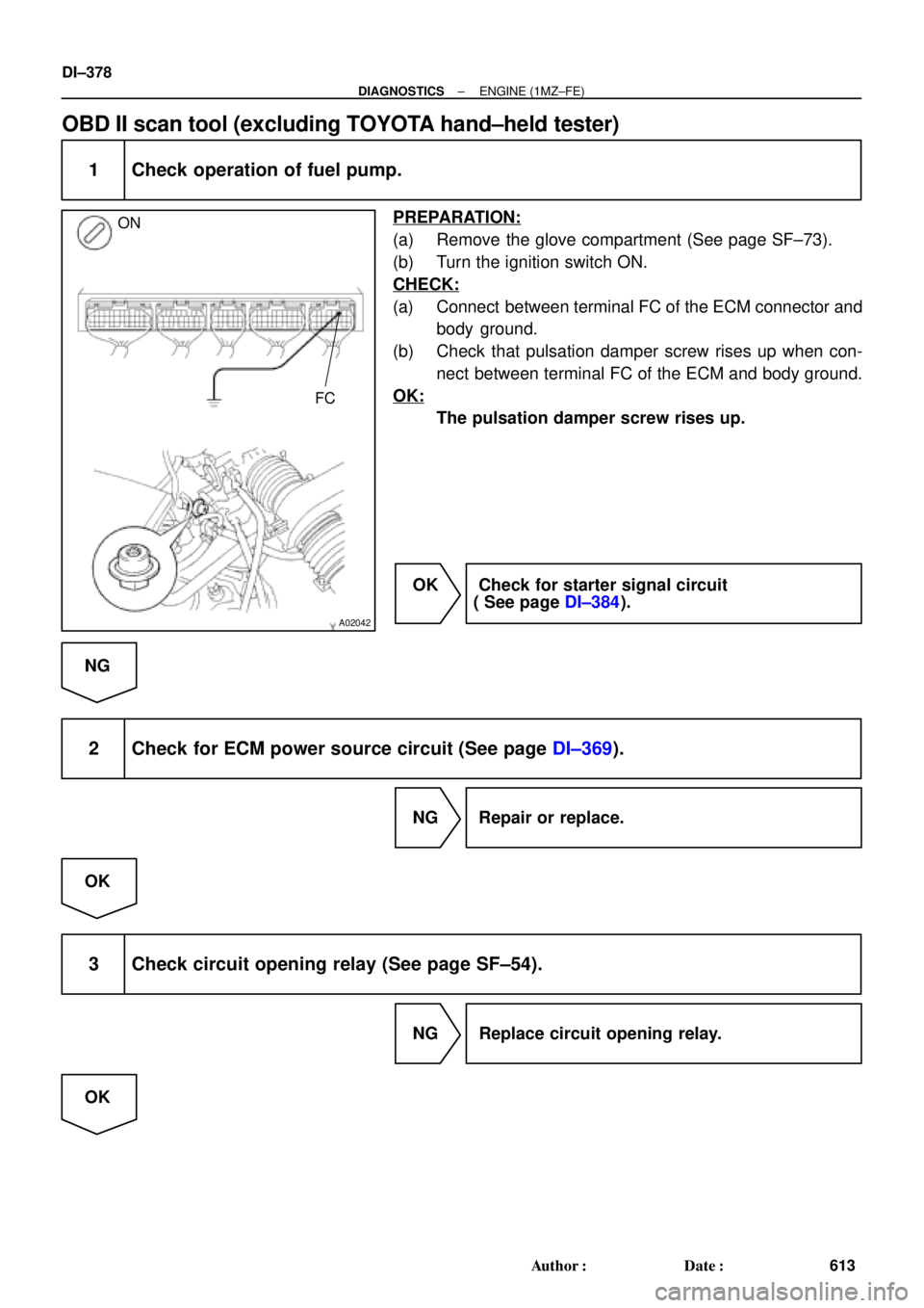
OBD II scan tool (excluding TOYOTA hand±held tester)
1 Check operation of fuel pump.
PREPARATION:
(a) Remove the glove compartment (See page SF±73).
(b) Turn the ignition switch ON.
CHECK:
(a) Connect between terminal FC of the ECM connector and
body ground.
(b) Check that pulsation damper screw rises up when con-
nect between terminal FC of the ECM and body ground.
OK:
The pulsation damper screw rises up.
OK Check for starter signal circuit
( See page DI±384).
NG
2 Check for ECM power source circuit (See page DI±369).
NG Repair or replace.
OK
3 Check circuit opening relay (See page SF±54).
NG Replace circuit opening relay.
OK
Page 3363 of 4770
EVAPORATIVE EMISSION (EVAP) CONTROL SYSTEM
1404 Author�: Date�:
INSPECTION
1. INSPE")
EC03E±05
B01082B04812B06707
Type A
Type BGasket
Gasket
B06544
Vacuum
Gauge
S05331
EC±6
± EMISSION CONTROL (5S±FE)EVAPORATIVE EMISSION (EVAP) CONTROL SYSTEM
1404 Author�: Date�:
INSPECTION
1. INSPECT LINES AND CONNECTORS
Visually check for loose connections, sharp bends or damage.
2. INSPECT FUEL TANK FILLER PIPE
Visually check for deformation, cracks or fuel leakage.
3. INSPECT FUEL TANK CAP
Visually check if the cap and/or gasket are deformed or dam-
aged.
If necessary, repair or replace the cap.
4. INSPECT EVAP SYSTEM LINE
(a) Warm up the engine and stop the engine.
Allow the engine to warm up to normal operating tempera-
ture.
(b) Install a vacuum gauge (EVAP control system test equip-
ment vacuum gauge) to the EVAP service port on the
purge line.
(c) TOYOTA Hand±Held Tester:
Forced driving of the VSV for the EVAP.
(1) Connect a TOYOTA hand±held tester to the DLC3.
(2) Start the engine.
(3) Push the TOYOTA hand±held tester main switch
ON.
(4) Use the ACTIVE TEST mode on the TOYOTA
hand±held tester to operate the VSV for the EVAP.
Page 3380 of 4770
EVAPORATIVE EMISSION (EVAP) CONTROL SYSTEM
1421 Auth")
EC0AV±01
B01082B04812B06707
Type A
Type BGasket
Gasket
B06544
Vacuum
Gauge
S05331
TOYOTA
Hand±Held Tester
DLC3
EC±6
± EMISSION CONTROL (1MZ±FE)EVAPORATIVE EMISSION (EVAP) CONTROL SYSTEM
1421 Author�: Date�:
INSPECTION
1. INSPECT LINES AND CONNECTORS
Visually check for loose connections, sharp bends or damage.
2. INSPECT FUEL TANK FILLER PIPE
Visually check for deformation, cracks or fuel leakage.
3. INSPECT FUEL TANK CAP
Visually check if the cap and/or gasket are deformed or dam-
aged.
If necessary, repair or replace the cap.
4. INSPECT EVAP SYSTEM LINE
(a) Warm up the engine and stop the engine.
Allow the engine to warm up to normal operating tempera-
ture.
(b) Install a vacuum gauge (EVAP control system test equip-
ment vacuum gauge) to the EVAP service port on the
purge line.
(c) TOYOTA Hand±Held Tester:
Forced driving of the VSV for the EVAP.
(1) Connect a TOYOTA hand±held tester to the DLC3.
(2) Start the engine.
(3) Push the TOYOTA hand±held tester main switch
ON.
(4) Use the ACTIVE TEST mode on the TOYOTA
hand±held tester to operate the VSV for the EVAP.
Page 3659 of 4770

IG0DF±01
CHECK POWER SUPPLY OF HIGH±TENSION COIL AND IGNITER
SPARK TEST
CHECK RESISTANCE OF HIGH±TENSION CORD
Maximum resistance: 25 kW per cord
CHECK RESISTANCE OF IGNITION COIL 1. Turn ignition switch to ON.
2. Check that there is battery voltage at ignition
coil positive (+) terminal. CHECK CONNECTION OF IGNITION COIL AND IGNITER
Resistance:
Cold Hot
Secondary
10.8 ± 14.9 kW13.1 ± 17.5 kWReplace the ignition coil (s). Connect securely.
Replace the cord(s).
Check wiring between ignition switch to
ignition coil and igniter.
NO
OK OK
OKBAD
BAD
BAD
BAD
CONNECTORS
Primary
0.70 ± 0.94 W0.85 ± 1.10 W AISAN made:
Secondary
6.8 ± 11.7 kW8.6 ± 13.7 kW Primary
0.70 ± 0.94 W0.85 ± 1.10 W Diamond made:
OK
Continue to the next page
± IGNITION (1MZ±FE)IGNITION SYSTEM
IG±1
1695 Author�: Date�:
IGNITION SYSTEM
ON±VEHICLE INSPECTION
NOTICE:
ºColdº and ºHotº in these sentences express the tempera-
ture of the coils themselves. ºColdº is from ±10°C (14°F) to
50°C (122°F) and ºHotº is from 50°C (122°F) to 100°C
(212°F).
1. INSPECT IGNITER AND SPARK TEST
Check that the spark occurs.
(1) Remove the ignition coil.
(2) Remove the spark plug.
(3) Install the spark plug to the ignition coil, and connect
the ignition coil connector.
(4) Ground the spark plug.
(5) Check if spark occurs while engine is being
cranked.
NOTICE:
To prevent excess fuel being injected from the injectors
during this test, do not crank the engine for more 5 ± 10 se-
conds at a time.
If the spark does not occur, do the test as follows:
Page 3688 of 4770

± INTRODUCTIONFOR ALL OF VEHICLES
IN±17
17 Author�: Date�:
2. FOR VEHICLES EQUIPPED WITH A CATALYTIC CONVERTER
CAUTION:
If large amount of unburned gasoline flows into the converter, it may overheat and create a fire haz-
ard. To prevent this, observe the following precautions and explain them to your customer.
(a) Use only unleaded gasoline.
(b) Avoid prolonged idling.
Avoid running the engine at idle speed for more than 20 minutes.
(c) Avoid spark jump test.
(1) Perform spark jump test only when absolutely necessary. Perform this test as rapidly as possible.
(2) While testing, never race the engine.
(d) Avoid prolonged engine compression measurement.
Engine compression tests must be done as rapidly as possible.
(e) Do not run engine when fuel tank is nearly empty.
This may cause the engine to misfire and create an extra load on the converter.
(f) Avoid coasting with ignition turned off.
(g) Do not dispose of used catalyst along with parts contaminated with gasoline or oil.
3. IF VEHICLE IS EQUIPPED WITH MOBILE COMMUNICATION SYSTEM
For vehicles with mobile communication systems such as two±way radios and cellular telephones, observe
the following precautions.
(1) Install the antenna as far as possible away from the ECU and sensors of the vehicle's electronic
system.
(2) Install the antenna feeder at least 20 cm (7.87 in.) away from the ECU and sensors of the ve-
hicle's electronic systems. For details about ECU and sensors locations, refer to the section on
the applicable component.
(3) Avoid winding the antenna feeder together with other wiring as much as possible, and also avoid
running the antenna feeder parallel with other wire harnesses.
(4) Check that the antenna and feeder are correctly adjusted.
(5) Do not install powerful mobile communications system.