Page 4107 of 4770
S06086
Fuel Hose
Clamp
S05352
S05364
SST
SST
Retainer
No.1 Fuel
Fuel Tube
Connector (Hose)
Pipe
SST
(Hose)SST
± SFI (1MZ±FE)FUEL PUMP
SF±7
1506 Author�: Date�:
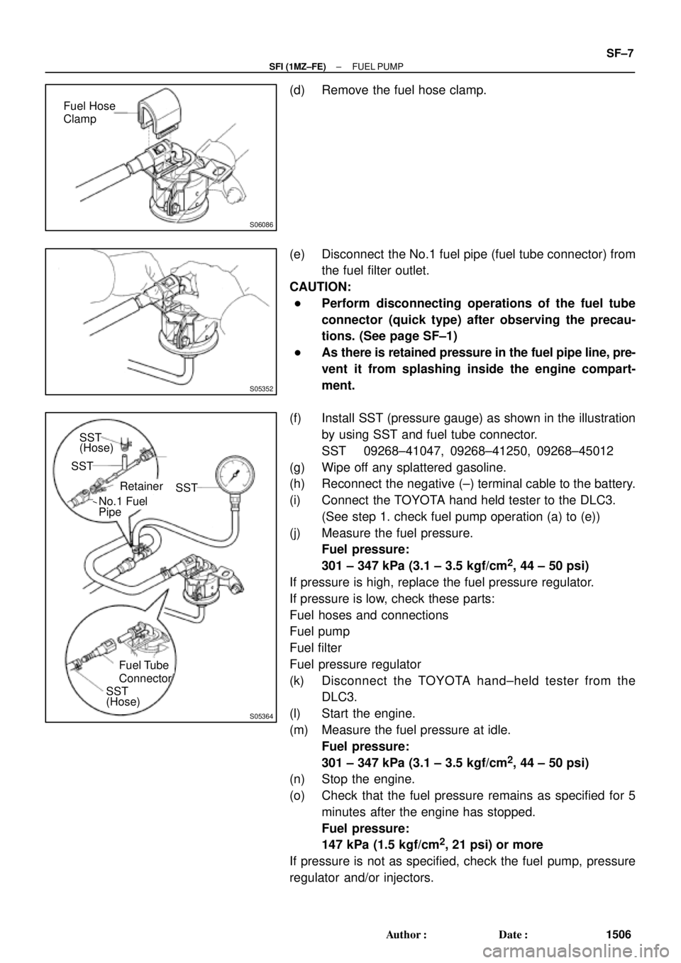
(d) Remove the fuel hose clamp.
(e) Disconnect the No.1 fuel pipe (fuel tube connector) from
the fuel filter outlet.
CAUTION:
�Perform disconnecting operations of the fuel tube
connector (quick type) after observing the precau-
tions. (See page SF±1)
�As there is retained pressure in the fuel pipe line, pre-
vent it from splashing inside the engine compart-
ment.
(f) Install SST (pressure gauge) as shown in the illustration
by using SST and fuel tube connector.
SST 09268±41047, 09268±41250, 09268±45012
(g) Wipe off any splattered gasoline.
(h) Reconnect the negative (±) terminal cable to the battery.
(i) Connect the TOYOTA hand held tester to the DLC3.
(See step 1. check fuel pump operation (a) to (e))
(j) Measure the fuel pressure.
Fuel pressure:
301 ± 347 kPa (3.1 ± 3.5 kgf/cm
2, 44 ± 50 psi)
If pressure is high, replace the fuel pressure regulator.
If pressure is low, check these parts:
Fuel hoses and connections
Fuel pump
Fuel filter
Fuel pressure regulator
(k) Disconnect the TOYOTA hand±held tester from the
DLC3.
(l) Start the engine.
(m) Measure the fuel pressure at idle.
Fuel pressure:
301 ± 347 kPa (3.1 ± 3.5 kgf/cm
2, 44 ± 50 psi)
(n) Stop the engine.
(o) Check that the fuel pressure remains as specified for 5
minutes after the engine has stopped.
Fuel pressure:
147 kPa (1.5 kgf/cm
2, 21 psi) or more
If pressure is not as specified, check the fuel pump, pressure
regulator and/or injectors.
Page 4108 of 4770
S05351
S06086
Fuel Hose
Clamp
S04508
Ohmmeter
4 5
S04509
4 5
Battery SF±8
± SFI (1MZ±FE)FUEL PUMP
1507 Author�: Date�:
(p) After checking fuel pressure, disconnect the negative (±)
terminal cable from the battery and carefully remove the
SST and fuel tube connector to prevent gasoline from
splashing.
SST 09268±41047, 09268±41250, 09268±45012
(q) Reconnect the No.1 fuel pipe (fuel tube connector).
CAUTION:
Perform connecting operations of the fuel tube connector
(quick type) after observing the precautions.
(See page SF±1)
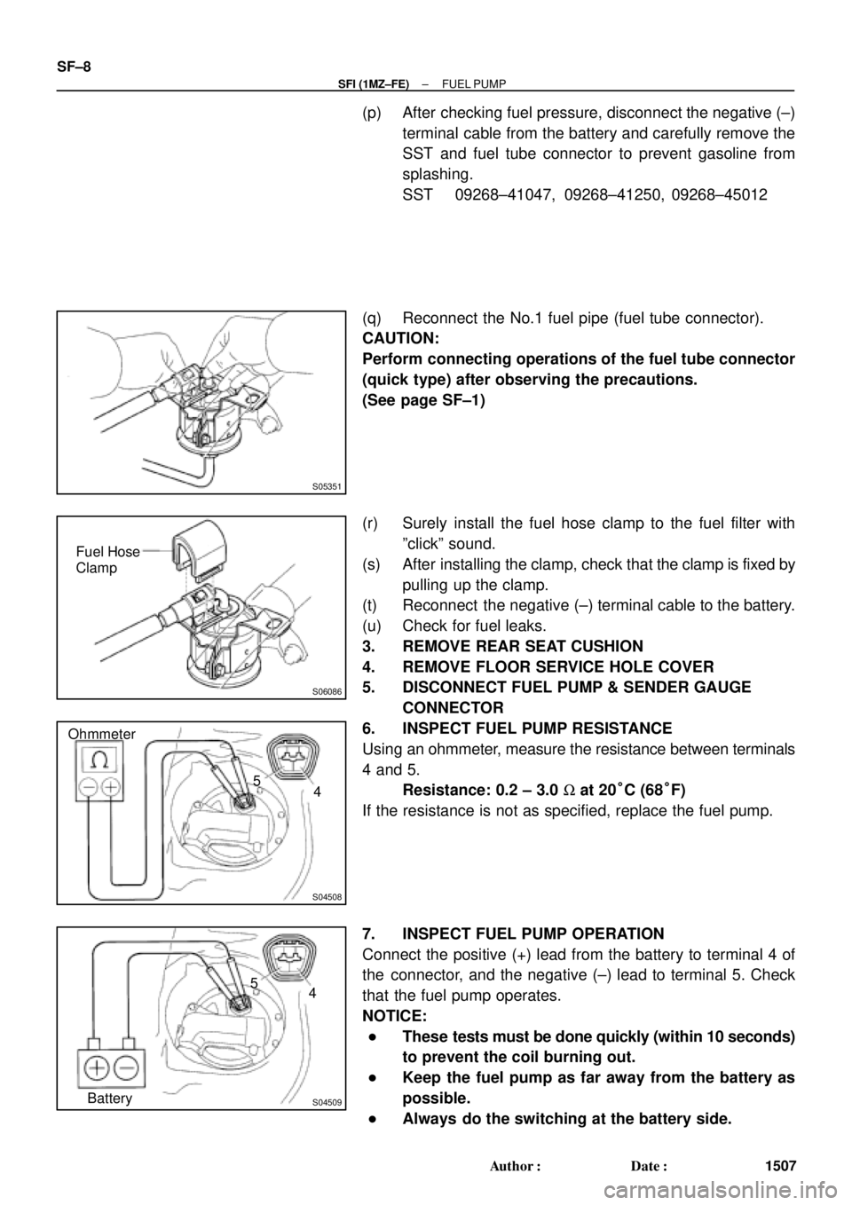
(r) Surely install the fuel hose clamp to the fuel filter with
ºclickº sound.
(s) After installing the clamp, check that the clamp is fixed by
pulling up the clamp.
(t) Reconnect the negative (±) terminal cable to the battery.
(u) Check for fuel leaks.
3. REMOVE REAR SEAT CUSHION
4. REMOVE FLOOR SERVICE HOLE COVER
5. DISCONNECT FUEL PUMP & SENDER GAUGE
CONNECTOR
6. INSPECT FUEL PUMP RESISTANCE
Using an ohmmeter, measure the resistance between terminals
4 and 5.
Resistance: 0.2 ± 3.0 W at 20°C (68°F)
If the resistance is not as specified, replace the fuel pump.
7. INSPECT FUEL PUMP OPERATION
Connect the positive (+) lead from the battery to terminal 4 of
the connector, and the negative (±) lead to terminal 5. Check
that the fuel pump operates.
NOTICE:
�These tests must be done quickly (within 10 seconds)
to prevent the coil burning out.
�Keep the fuel pump as far away from the battery as
possible.
�Always do the switching at the battery side.
Page 4125 of 4770
SF07L±04
B01919
Fuel Tube Connector
SST
(Hose)
SST
(Union)
SST
(Clamp)
InjectorFuel Filter
(On Vehicle) California A/T
Except California A/T
Fuel Tube Connector
SST
(Hose)
SST
(Union)
SST
(Clamp)
InjectorFuel Filter
(On Vehicle)
S05359
Fuel Tube Connector
S05357
SST
(Hose) Fuel Tube Connector
Fuel Filter
± SFI (1MZ±FE)INJECTOR
SF±25
1524 Author�: Date�:
INSPECTION
1. INSPECT INJECTOR INJECTION
CAUTION:
Keep injector clear of sparks during the test.
(a) Purchase the new No.1 fuel pipe and take out the fuel
tube connector from its pipe.
Part No. 23801±20041
(b) Connect SST (hose ) and fuel tube connector to the fuel
filter outlet.
SST 09268±41047
CAUTION:
Preform connecting operations of the fuel tube connector
(quick type) after observing the precautions.
(See page SF±1)
HINT:
Use the vehicle fuel filter.
Page 4126 of 4770
B01914
SST (Union)SST (Hose)
O±Ring
SST
(Clamp)
Vinyl Tube
Vinyl Tube
O±Ring
SST (Union)
SST (Hose)
SST
(Clamp)
California A/T
Except California A/T
S05358
TOYOTA
Hand±Held Tester SF±26
± SFI (1MZ±FE)INJECTOR
1525 Author�: Date�:
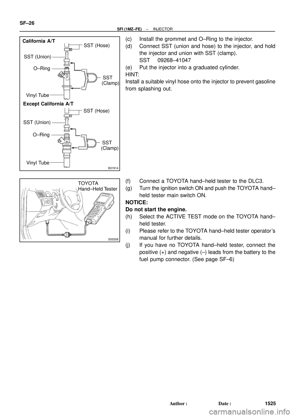
(c) Install the grommet and O±Ring to the injector.
(d) Connect SST (union and hose) to the injector, and hold
the injector and union with SST (clamp).
SST 09268±41047
(e) Put the injector into a graduated cylinder.
HINT:
Install a suitable vinyl hose onto the injector to prevent gasoline
from splashing out.
(f) Connect a TOYOTA hand±held tester to the DLC3.
(g) Turn the ignition switch ON and push the TOYOTA hand±
held tester main switch ON.
NOTICE:
Do not start the engine.
(h) Select the ACTIVE TEST mode on the TOYOTA hand±
held tester.
(i) Please refer to the TOYOTA hand±held tester operator's
manual for further details.
(j) If you have no TOYOTA hand±held tester, connect the
positive (+) and negative (±) leads from the battery to the
fuel pump connector. (See page SF±6)
Page 4127 of 4770
B01913
California A/T
Except California A/TBatterySST
(Wire)
BatterySST
(Wire)
B00628
California A/TExcept
California A/T
± SFI (1MZ±FE)INJECTOR
SF±27
1526 Author�: Date�:
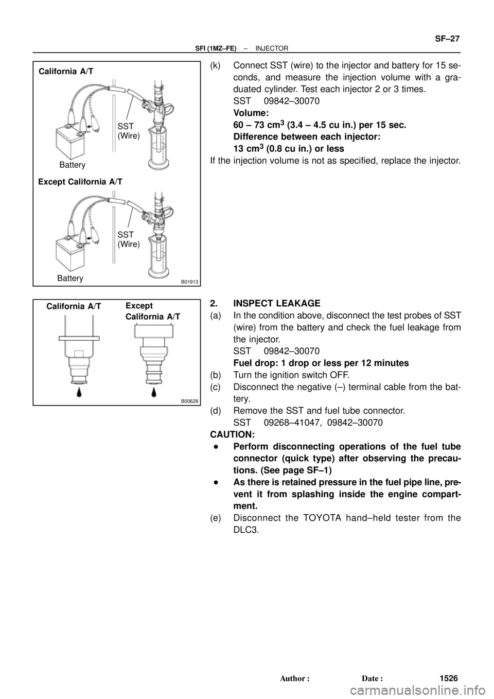
(k) Connect SST (wire) to the injector and battery for 15 se-
conds, and measure the injection volume with a gra-
duated cylinder. Test each injector 2 or 3 times.
SST 09842±30070
Volume:
60 ± 73 cm
3 (3.4 ± 4.5 cu in.) per 15 sec.
Difference between each injector:
13 cm
3 (0.8 cu in.) or less
If the injection volume is not as specified, replace the injector.
2. INSPECT LEAKAGE
(a) In the condition above, disconnect the test probes of SST
(wire) from the battery and check the fuel leakage from
the injector.
SST 09842±30070
Fuel drop: 1 drop or less per 12 minutes
(b) Turn the ignition switch OFF.
(c) Disconnect the negative (±) terminal cable from the bat-
tery.
(d) Remove the SST and fuel tube connector.
SST 09268±41047, 09842±30070
CAUTION:
�Perform disconnecting operations of the fuel tube
connector (quick type) after observing the precau-
tions. (See page SF±1)
�As there is retained pressure in the fuel pipe line, pre-
vent it from splashing inside the engine compart-
ment.
(e) Disconnect the TOYOTA hand±held tester from the
DLC3.
Page 4175 of 4770
S04528
5 mm
Hexagon
Wrench
Clip
SF08T±03
S05358
TOYOTA
Hand±Held Tester
B00623
Sound Scope
Sound Scope California A/T
Except California A/T
± SFI (1MZ±FE)FUEL CUT RPM
SF±75
1574 Author�: Date�:
FUEL CUT RPM
INSPECTION
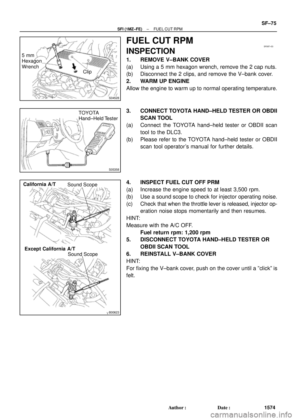
1. REMOVE V±BANK COVER
(a) Using a 5 mm hexagon wrench, remove the 2 cap nuts.
(b) Disconnect the 2 clips, and remove the V±bank cover.
2. WARM UP ENGINE
Allow the engine to warm up to normal operating temperature.
3. CONNECT TOYOTA HAND±HELD TESTER OR OBDII
SCAN TOOL
(a) Connect the TOYOTA hand±held tester or OBDII scan
tool to the DLC3.
(b) Please refer to the TOYOTA hand±held tester or OBDII
scan tool operator's manual for further details.
4. INSPECT FUEL CUT OFF PRM
(a) Increase the engine speed to at least 3,500 rpm.
(b) Use a sound scope to check for injector operating noise.
(c) Check that when the throttle lever is released, injector op-
eration noise stops momentarily and then resumes.
HINT:
Measure with the A/C OFF.
Fuel return rpm: 1,200 rpm
5. DISCONNECT TOYOTA HAND±HELD TESTER OR
OBDII SCAN TOOL
6. REINSTALL V±BANK COVER
HINT:
For fixing the V±bank cover, push on the cover until a ºclickº is
felt.
Page 4533 of 4770
READINESS MONITOR DRIVE PATTERNS ± EG003-02 RevisedMarch 29, 2002
Page 2 of 23
J1930 TERMJ1930 DEFINITIONTOYOTA/LEXUS DIAGNOSTIC TESTER PARAMETER
IATIntake Air TemperatureIntake Air
ECTEngine Coolant TemperatureCoolant Temp
TOOLS & MATERIALPART NUMBERQUANTITY
Toyota Diagnostic Tester Kit010012711
12 Megabyte Diagnostic Tester Program Card
with version 9.0a Software (or later)01002593-0051
NOTE:
A generic OBDII Scantool can be used in place of the Toyota Diagnostic Tester.
CAUTION:
Strict observance of posted speed limits, traffic laws and road conditions are
required when performing these drive patterns.
NOTE:
�These drive patterns represent the fastest method to satisfy all necessary
conditions which allow the specific Readiness Monitor to complete.
�In the event that the drive pattern must be interrupted (possibly due to traffic
conditions or other factors) the drive pattern can be resumed and, in most cases,
the Readiness Monitor will still set to ªcomplete.º
�To ensure rapid completion of Readiness Monitors, avoid sudden changes in
vehicle load and speed (driving up and down hills and/or sudden acceleration).
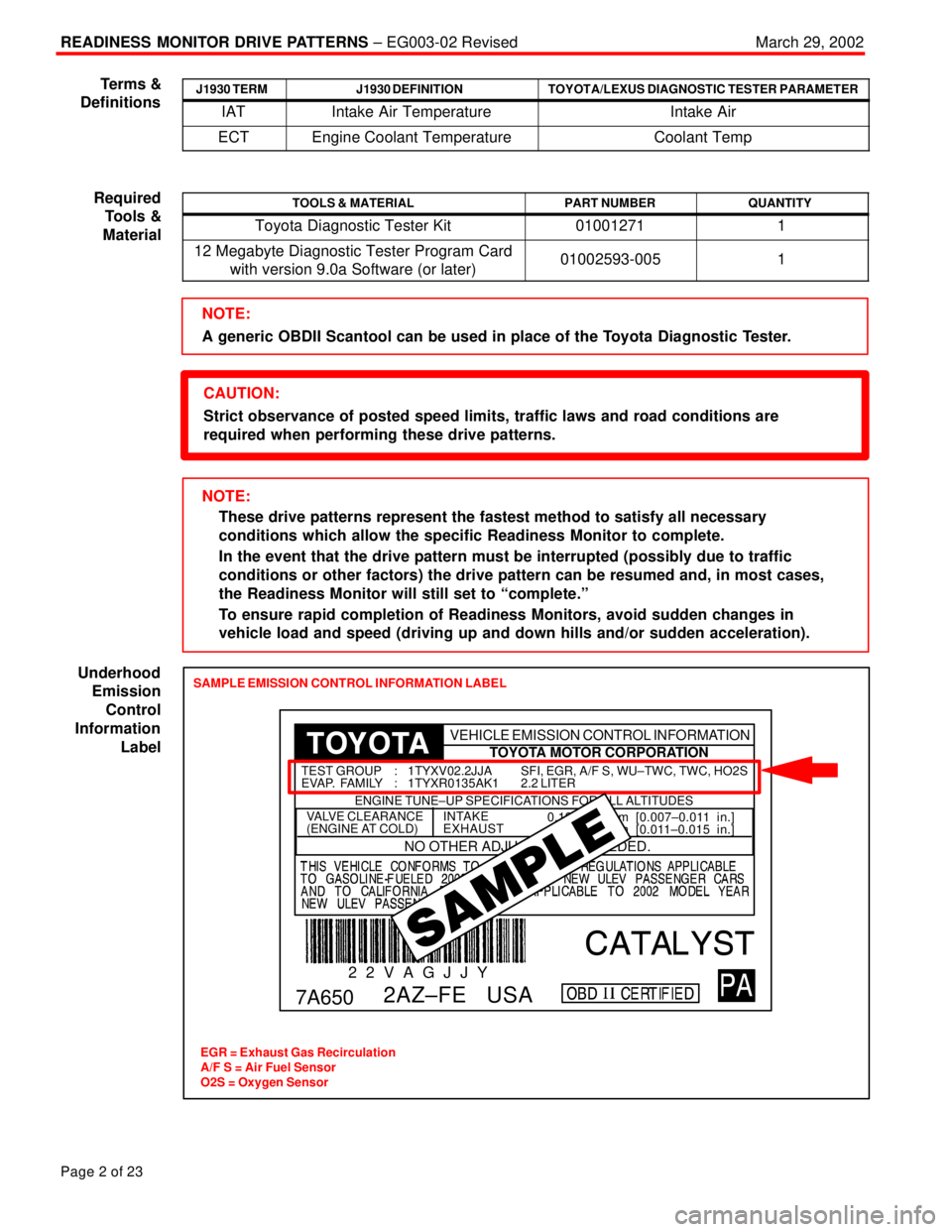
SAMPLE EMISSION CONTROL INFORMATION LABEL
EGR = Exhaust Gas Recirculation
A/F S = Air Fuel Sensor
O2S = Oxygen Sensor
0.19±0.29 mm [0.007±0.011 in.]
0.28±0.38 mm [0.011±0.015 in.]INTAKE
EXHAUSTVALVE CLEARANCE
(ENGINE AT COLD)
NO OTHER ADJUSTMENTS NEEDED.
ENGINE TUNE±UP SPECIFICATIONS FOR ALL ALTITUDES
7A650
2 2 V A G J J Y
2AZ±FE USA
SFI, EGR, A/F S, WU±TWC, TWC, HO2S
2.2 LITER TEST GROUP : 1TYXV02.2JJA
EVAP. FAMILY : 1TYXR0135AK1
TOYOTA MOTOR CORPORATION VEHICLE EMISSION CONTROL INFORMATION
Terms &
Definitions
Required
Tools &
Material
Underhood
Emission
Control
Information
Label
Page 4547 of 4770
READINESS MONITOR DRIVE PATTERNS ± EG003-02 RevisedMarch 29, 2002
Page 16 of 23
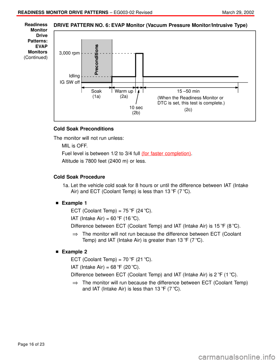
DRIVE PATTERN NO. 6: EVAP Monitor (Vacuum Pressure Monitor/Intrusive Type)
Idling
IG SW off
Warm up
(2a) Soak
(1a)15 ±50 min
(When the Readiness Monitor or
DTC is set, this test is complete.)
(2c)
10 sec
(2b)
3,000 rpm
Cold Soak Preconditions
The monitor will not run unless:
�MIL is OFF.
�Fuel level is between 1/2 to 3/4 full (for faster completion)
.
�Altitude is 7800 feet (2400 m) or less.
Cold Soak Procedure
1a. Let the vehicle cold soak for 8 hours or until the difference between IAT (Intake
Air) and ECT (Coolant Temp) is less than 13�F (7�C).
�Example 1
�ECT (Coolant Temp) = 75�F (24�C).
�IAT (Intake Air) = 60�F (16�C).
�Difference between ECT (Coolant Temp) and IAT (Intake Air) is 15�F (8�C).
%The monitor will not run because the difference between ECT (Coolant
Temp) and IAT (Intake Air) is greater than 13�F (7�C).
�Example 2
�ECT (Coolant Temp) = 70�F (21�C).
�IAT (Intake Air) = 68�F (20�C).
�Difference between ECT (Coolant Temp) and IAT (Intake Air) is 2�F (1�C).
%The monitor will run because the difference between ECT (Coolant Temp)
and IAT (Intake Air) is less than 13�F (7�C).
Readiness
Monitor
Drive
Patterns:
EVAP
Monitors
(Continued)