Page 2481 of 4770

Platinum Electrode
Heater
Coating (Ceramic)
Exhaust GasCoverIdeal Air±Fuel Mixture
Output Voltage
Richer")
P21242 FI7210
A00027
Atmosphere
Flange
Platinum Electrode
Solid Electrolyte
(Zirconia Element)
Platinum Electrode
Heater
Coating (Ceramic)
Exhaust GasCoverIdeal Air±Fuel Mixture
Output Voltage
Richer ± Air Fuel Ratio ± Leaner
± DIAGNOSTICSENGINE (5S±FE)
DI±61
296 Author�: Date�:
DTC P0125 Insufficient Coolant Temp. for Closed Loop
Fuel Control (Except California Spec.)
CIRCUIT DESCRIPTION
To obtain a high purification rate for the CO, HC and NOx components of the exhaust gas, a three±way
catalytic converter is used, but for the most efficient use of the three±way catalytic converter, the air±fuel
ratio must be precisely controlled so that it is always close to the stoichiometric air±fuel ratio.
The heated oxygen sensor has the characteristic where by its output voltage changes suddenly in the vicinity
of the stoichiometric air±fuel ratio. This is used to detect the oxygen concentration in the exhaust gas and
provide feedback to the computer for control of the air±fuel ratio.
When the air±fuel ratio becomes LEAN, the oxygen concentration in the exhaust increases and the heated
oxygen sensor informs the ECM of the LEAN condition (small electromotive force: 0 V).
When the air±fuel ratio is RICHER than the stoichiometric air±fuel ratio the oxygen concentration in the ex-
haust gas is reduced and the heated oxygen sensor informs the ECM of the RICH condition (large electromo-
tive force: 1 V).
The ECM judges by the electromotive force from the heated oxygen sensor whether the air±fuel ratio is RICH
or LEAN and controls the injection time accordingly. However, if malfunction of the heated oxygen sensor
causes output of abnormal electromotive force, the ECM is unable to perform accurate air±fuel ratio control.
The heated oxygen sensors include a heater which heats the zirconia element. The heater is controlled by
the ECM. When the intake air volume is low (the temperature of the exhaust gas is low) current flows to the
heater to heat the sensor for accurate oxygen concentration detection.
DTC No.DTC Detecting ConditionTrouble Area
P0125
After engine is warmed up, heated oxygen sensor (bank 1
sensor 1) output does not indicate RICH even once when
conditions (a), (b) and (c) continue for at least 1.5 min.:
(a) Engine speed: 1,500 rpm or more
(b) Vehicle speed: 40 ~ 100 km/h (25 ~ 62 mph)
(c) Throttle valve does not fully closed
�Fuel system
�Injector
�Ignition system
�Gas leakage on exhaust system
�Open or short in heated oxygen sensor (bank 1 sensor 1)
circuit
�Heated oxygen sensor (bank 1 sensor 1)
�ECM
DI00T±05
Page 2495 of 4770

DI±75
310 Author�: Date�:
DTC P0135 Heated Oxygen Sensor Heater Circuit Mal-
function (Bank 1 Sensor 1) (Ex. CA Spec.)
DTC P0141 Heated Oxygen Sensor Heater Circuit
Mal")
± DIAGNOSTICSENGINE (5S±FE)
DI±75
310 Author�: Date�:
DTC P0135 Heated Oxygen Sensor Heater Circuit Mal-
function (Bank 1 Sensor 1) (Ex. CA Spec.)
DTC P0141 Heated Oxygen Sensor Heater Circuit
Malfunction (Bank 1 Sensor 2)
CIRCUIT DESCRIPTION
Refer to DTC P0125 (Insufficient Coolant Temp. for Closed Loop Fuel Control (Except California Spec.)) on
page DI±55.
DTC No.DTC Detecting ConditionTrouble Area
P0135
P0141When heater operates, heater current exceeds 2 A
(2 trip detection logic)�Open or short in heater circuit of heated oxygen sensor
Htd htP0135
P0141Heater current of 0.2 A or less when heater operates
(2 trip detection logic)�Heated oxygen sensor heater
�ECM
HINT:
�Sensor 1 refers to the sensor closer to the engine body.
�Sensor 2 refers to the sensor farther away from the engine body.
WIRING DIAGRAM
Refer to DTC P0125 (Insufficient Coolant Temp. for Closed Loop Fuel Control (Except California Spec.)) on
page DI±55.
INSPECTION PROCEDURE
HINT:
Read freeze frame data using TOYOTA hand±held tester or OBD II scan tool. Because freeze frame records
the engine conditions when the malfunction is detected, when troubleshooting it is useful for determining
whether the vehicle was running or stopped, the engine warmed up or not, the air±fuel ratio lean or rich, etc.
at the time of the malfunction.
DI00X±04
Page 2496 of 4770
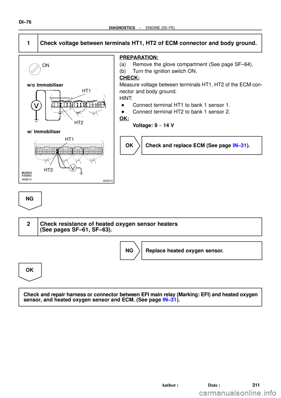
A03014A03415
ON
HT1
HT2
w/o Immobiliser
w/ Immobiliser
HT1
HT2
DI±76
± DIAGNOSTICSENGINE (5S±FE)
311 Author�: Date�:
1 Check voltage between terminals HT1, HT2 of ECM connector and body ground.
PREPARATION:
(a) Remove the glove compartment (See page SF±64).
(b) Turn the ignition switch ON.
CHECK:
Measure voltage between terminals HT1, HT2 of the ECM con-
nector and body ground.
HINT:
�Connect terminal HT1 to bank 1 sensor 1.
�Connect terminal HT2 to bank 1 sensor 2.
OK:
Voltage: 9 ~ 14 V
OK Check and replace ECM (See page IN±31).
NG
2 Check resistance of heated oxygen sensor heaters
(See pages SF±61, SF±63).
NG Replace heated oxygen sensor.
OK
Check and repair harness or connector between EFI main relay (Marking: EFI) and heated oxygen
sensor, and heated oxygen sensor and ECM. (See page IN±31).
Page 2575 of 4770
± DIAGNOSTICSENGINE (5S±FE)
DI±155
390 Author�: Date�:
4 Check resistance of A/F sensor heater (See page SF±59).
NG Replace A/F sensor.
OK
5 Check air induction system (See page SF±1).
NG Repair or replace.
OK
6 Check EGR system (See page EC±12).
NG Repair EGR system.
OK
7 Check fuel pressure (See page SF±6).
NG Check and repair fuel pump, fuel pipe line and
filter (See page SF±1).
OK
Page 2579 of 4770
± DIAGNOSTICSENGINE (5S±FE)
DI±159
394 Author�: Date�:
4 Check resistance of A/F sensor heater (See page SF±59).
NG Replace A/F sensor.
OK
5 Check air induction system (See page SF±1).
NG Repair or replace.
OK
6 Check EGR system (See page EC±12).
NG Repair EGR system.
OK
7 Check fuel pressure (See page SF±6).
NG Check and repair fuel pump, fuel pipe line and
filter (See page SF±1).
OK
Page 2581 of 4770
 ON
± DIAGNOSTICSENGINE (5S±FE)
DI±161
396 Author�: Date�:
DTC P1135 A/F Sensor Heater Circuit Malfunction
(Only for California Spec.)
CIRCUIT DESCRIPTION
Refer to DTC P0125 (Insuffi")
A00430
HTAF (+) ON
± DIAGNOSTICSENGINE (5S±FE)
DI±161
396 Author�: Date�:
DTC P1135 A/F Sensor Heater Circuit Malfunction
(Only for California Spec.)
CIRCUIT DESCRIPTION
Refer to DTC P0125 (Insufficient Coolant Temp. for Closed Loop Fuel Control (Only for California Spec.))
on page DI±61.
DTC No.DTC Detecting ConditionTrouble Area
P1135
When heater operates, heater current exceeds 8 A
(2 trip detection logic)�Open or short in heater circuit of A/F sensor
A/F h tP1135Heater current of 0.25 A or less when heater operates
(2 trip detection logic)�A/F sensor heater
�ECM
WIRING DIAGRAM
Refer to DTC P0125 (Insufficient Coolant Temp. for Closed Loop Fuel Control (Only for California Spec.))
on page DI±61.
INSPECTION PROCEDURE
HINT:
Read freeze frame data using TOYOTA hand±held tester or OBD II scan tool. Because freeze frame records
the engine conditions when the malfunction is detected, when troubleshooting it is useful for determining
whether the vehicle was running or stopped, the engine warmed up or not, the air±fuel ratio lean or rich, etc.
at the time of the malfunction.
1 Check voltage between terminal HTAF of ECM connector and body ground.
PREPARATION:
(a) Remove the glove compartment (See page SF±64).
(b) Turn the ignition switch ON.
CHECK:
Measure voltage between terminals HTAF of the ECM connec-
tor and body ground.
OK:
Voltage: 9 ~ 14 V
OK Check and replace ECM (See page IN±31).
NG
DI01F±05
Page 2582 of 4770
DI±162
± DIAGNOSTICSENGINE (5S±FE)
397 Author�: Date�:
2 Check resistance of A/F sensor heater (See page SF±59).
NG Replace A/F sensor.
OK
Check and repair harness or connector between EFI main relay (Marking: EFI) and A/F sensor,
and A/F sensor and ECM (See page IN±31).
Page 2622 of 4770

437 Author�: Date�:
4. FAIL±SAFE CHART
If any of the following codes is recorded, the ECM enters fail±safe mode.
DTC No.Fail±Safe OperationFail±Safe Deactiva")
DI±202
± DIAGNOSTICSENGINE (1MZ±FE)
437 Author�: Date�:
4. FAIL±SAFE CHART
If any of the following codes is recorded, the ECM enters fail±safe mode.
DTC No.Fail±Safe OperationFail±Safe Deactivation Conditions
P0100Ignition timing fixed at 10° BTDCReturned to normal condition
P0110Intake air temperature is fixed at 20°C (68°F)Returned to normal condition
P0115Engine coolant temperature is fixed at 80°C (176°F)Returned to normal condition
P0120VTA is fixed at 0°
The following condition must be repeated at least 2 times
consecutively
(a) Vehicle speed: 0km/h (0mph)
(b) VTA ��0.1 V and � 0.95 V
P0135
P0141
P0155The heater circuit in which an abnormality is detected is
turned offIgnition switch OFF
P0325
P0330Max. timing retardationIgnition switch OFF
P1300Fuel cutIGF signal is detected for 6 consecutive ignition
5. CHECK FOR INTERMITTENT PROBLEMS
TOYOTA HAND±HELD TESTER only:
By putting the vehicle's ECM in check mode, 1 trip detection logic is possible instead of 2 trip detection logic
and sensitivity to detect open circuits is increased. This makes it easier to detect intermittent problems.
(1) Clear the DTC (See page DI±197).
(2) Set the check mode (See page DI±197).
(3) Perform a simulation test (See page IN±21).
(4) Check the connector and terminal (See page IN±31).
(5) Handle the connector (See page IN±31).
6. BASIC INSPECTION
When the malfunction code is not confirmed in the DTC check, troubleshooting should be performed in the
order for all possible circuits to be considered as the causes of the problems. In many cases, by carrying
out the basic engine check shown in the following flow chart, the location causing the problem can be found
quickly and efficiently. Therefore, use of this check is essential in engine troubleshooting.
1 Is battery positive voltage 11 V or more when engine is stopped ?
NO Charge or replace battery.
YES