Page 2763 of 4770
± DIAGNOSTICSENGINE (1MZ±FE)
DI±343
578 Author�: Date�:
3 Check for open and short in harness and connector between ECM and A/F sen-
sors (bank 1, 2 sensor 1) (See page IN±31).
NG Repair or replace harness or connector.
OK
4 Check resistance of A/F sensor heater (See page SF±68).
NG Replace A/F sensor.
OK
5 Check air induction system (See page SF±1).
NG Repair or replace.
OK
6 Check EGR system (See page EC±11).
NG Replace EGR system.
OK
7 Check fuel pressure (See page SF±21).
NG Check and repair fuel pump, fuel pipe line and
filter (See page SF±1).
OK
Page 2767 of 4770
± DIAGNOSTICSENGINE (1MZ±FE)
DI±347
582 Author�: Date�:
3 Check for open and short in harness and connector between ECM and A/F sen-
sors (bank 1, 2 sensor 1) (See page IN±31).
NG Repair or replace harness or connector.
OK
4 Check resistance of A/F sensor heater (See page SF±68).
NG Replace A/F sensor.
OK
5 Check air induction system (See page SF±1).
NG Repair or replace.
OK
6 Check EGR system (See page EC±11).
NG Replace EGR system.
OK
7 Check fuel pressure (See page SF±21).
NG Check and repair fuel pump, fuel pipe line and
filter (See page SF±1).
OK
Page 2769 of 4770
A02509
HAFL (+)
HAFR (+)
± DIAGNOSTICSENGINE (1MZ±FE)
DI±349
584 Author�: Date�:
DTC P1135 A/F Sensor Heater Circuit Malfunction
(Bank 1 Sensor 1) (Only for California Spec.)
DTC P1155 A/F Sensor Heater Circuit Malfunction
(Bank 2 Sensor 1) (Only for California Spec.)
CIRCUIT DESCRIPTION
Refer to DTC P0125 (Insufficient Coolant Temp. for Closed Loop Fuel Control (Only for California Spec.))
on page DI±249.
DTC No.DTC Detecting ConditionTrouble Area
P1135
When heater operates, heater current exceeds 8 A
(2 trip detection logic)�Open or in heater circuit of A/F sensors
(bank 1, 2 sensor 1)P1135
P1155Heater current of 0.25 A or less when heater operates
(2 trip detection logic)
(bank 1, 2 sensor 1)
�A/F sensors (bank 1, 2 sensor 1) heater
�ECM
WIRING DIAGRAM
Refer to DTC P0125 (Insufficient Coolant Temp. for Closed Loop Fuel Control (Only for California Spec.))
on page DI±249.
INSPECTION PROCEDURE
HINT:
Read freeze frame data using TOYOTA hand±held tester or OBD II scan tool. Because freeze frame records
the engine conditions when the malfunction is detected, when troubleshooting it is useful for determining
whether the vehicle was running or stopped, the engine warmed up or not, the air±fuel ratio lean or rich, etc.
at the time of the malfunction.
1 Check voltage between terminal HAFR, HAFL of ECM connector and body
ground.
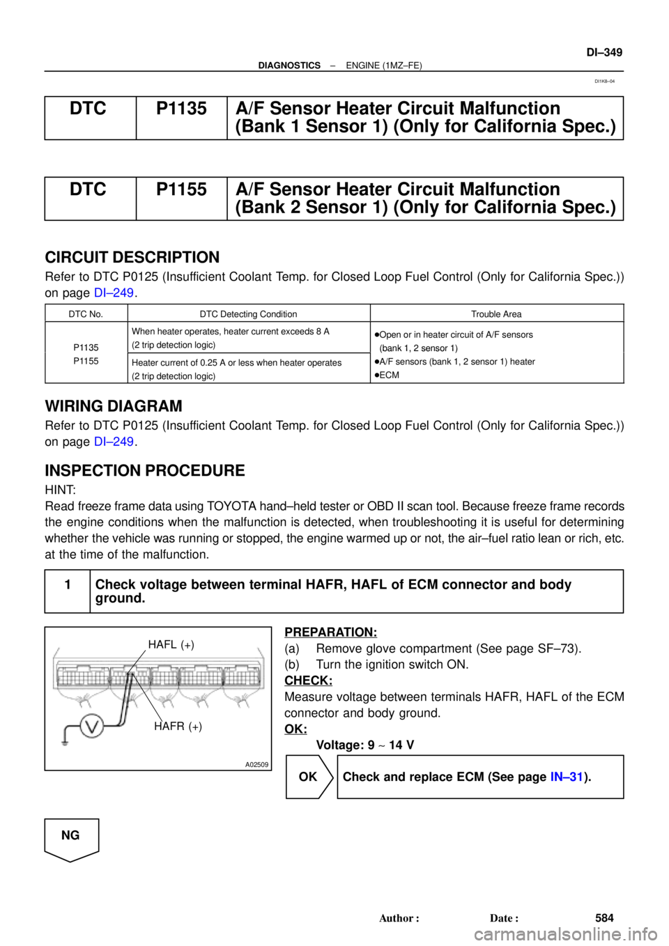
PREPARATION:
(a) Remove glove compartment (See page SF±73).
(b) Turn the ignition switch ON.
CHECK:
Measure voltage between terminals HAFR, HAFL of the ECM
connector and body ground.
OK:
Voltage: 9 ~ 14 V
OK Check and replace ECM (See page IN±31).
NG
DI1K8±04
Page 2770 of 4770
DI±350
± DIAGNOSTICSENGINE (1MZ±FE)
585 Author�: Date�:
2 Check resistance of A/F sensor heaters (bank 1, 2 sensor 1) (See page SF±68).
NG Replace A/F sensors (bank 1, 2 sensor 1).
OK
Check and repair harness or connector between EFI main relay (Marking: EFI) and A/F sensors
(bank 1, 2 sensor 1), and A/F sensors (bank 1, 2 sensor 1) and ECM (See page IN±31).
Page 3209 of 4770
AB0119H01298H01299
Airbag Sensor Assembly
ON
ACC
IG2
(+) (±)
H01249
ON
± DIAGNOSTICSSUPPLEMENTAL RESTRAINT SYSTEM
DI±789
1024 Author�: Date�:
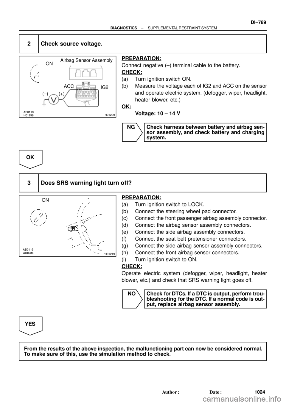
2 Check source voltage.
PREPARATION:
Connect negative (±) terminal cable to the battery.
CHECK:
(a) Turn ignition switch ON.
(b) Measure the voltage each of IG2 and ACC on the sensor
and operate electric system. (defogger, wiper, headlight,
heater blower, etc.)
OK:
Voltage: 10 ± 14 V
NG Check harness between battery and airbag sen-
sor assembly, and check battery and charging
system.
OK
3 Does SRS warning light turn off?
PREPARATION:
(a) Turn ignition switch to LOCK.
(b) Connect the steering wheel pad connector.
(c) Connect the front passenger airbag assembly connector.
(d) Connect the airbag sensor assembly connectors.
(e) Connect the side airbag assembly connectors.
(f) Connect the seat belt pretensioner connectors.
(g) Connect the side airbag sensor assembly connectors.
(h) Connect the front airbag sensor connectors.
(i) Turn ignition switch to ON.
CHECK:
Operate electric system (defogger, wiper, headlight, heater
blower, etc.) and check that SRS warning light goes off.
NO Check for DTCs. If a DTC is output, perform trou-
bleshooting for the DTC. If a normal code is out-
put, replace airbag sensor assembly.
YES
From the results of the above inspection, the malfunctioning part can now be considered normal.
To make sure of this, use the simulation method to check.
Page 3422 of 4770
A01562
Generator Wire
Generator
Connector
GeneratorWire Clamp
Wire
Clamp
ECT Sender
Gauge ConnectorThrottle BodyThrottle Position
Sensor ConnectorIgnition Coil Connector
IAC Valve
Connector
Heater Water Hose
Radiator Hose ECT Sensor
Connector
Water Outlet
Noise Filter Connector
Oil Pressure Switch Connector
Ignition Coil and No.2 Intake
Manifold Assembly
(with High±Tension Cord)
A/F Sensor Connector (California) or
Heated Oxygen Sensor (Bank 1 Sensor 1)
Connector (Except California)
(TMMK Made) � Gasket� Gasket � Gasket
(TMC Made)No.1 Exhaust
Manifold Stay
No.2 Exhaust
Manifold Stay No.1 Exhaust
Manifold Heat
Insulator
Exhaust Manifold,
No.2 and No.3
Exhaust Manifold
Heat Insulator
Assembly
� Non±reusable partExcept California
19 (195, 14)
49 (500, 36)
49 (500, 36)
: Specified torqueN´m (kgf´cm, ft´lbf)x 6
Exhaust Manifold,
No.2 and no.3
Exhaust Manifold
Heat Insulator
Assenbly
(California)
No.1 Exhaust
Manifold Heat
Insulator (California) (TMMK Made)
(TMC Made)
EM±30
± ENGINE MECHANICAL (5S±FE)CYLINDER HEAD
1202 Author�: Date�:
Page 3426 of 4770
S05548
Wire
Clamp
A01564(c)(d)
(e)
A07364
ConnectorClamp
EM±34
± ENGINE MECHANICAL (5S±FE)CYLINDER HEAD
1206 Author�: Date�:
(j) California:
Disconnect the A/F sensor connector for the wiring side
from the bracket on the LH engine hanger.
(k) Except California:
Disconnect the heated oxygen sensor (bank 1 sensor 1)
connector for the wiring side from the bracket on the LH
engine hanger.
5. REMOVE THROTTLE BODY (See page SF±32)
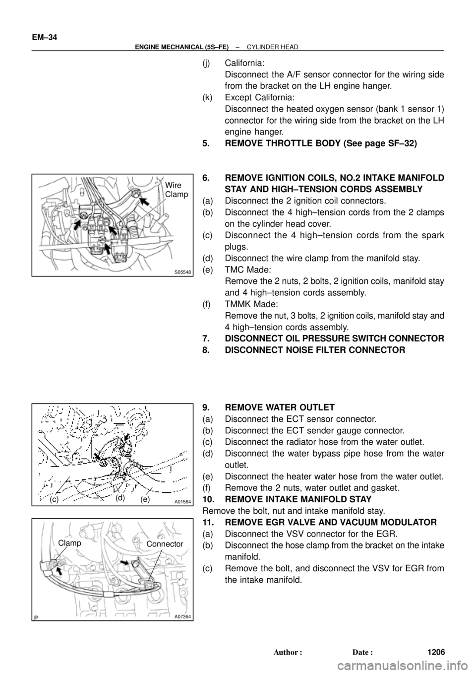
6. REMOVE IGNITION COILS, NO.2 INTAKE MANIFOLD
STAY AND HIGH±TENSION CORDS ASSEMBLY
(a) Disconnect the 2 ignition coil connectors.
(b) Disconnect the 4 high±tension cords from the 2 clamps
on the cylinder head cover.
(c) Disconnect the 4 high±tension cords from the spark
plugs.
(d) Disconnect the wire clamp from the manifold stay.
(e) TMC Made:
Remove the 2 nuts, 2 bolts, 2 ignition coils, manifold stay
and 4 high±tension cords assembly.
(f) TMMK Made:
Remove the nut, 3 bolts, 2 ignition coils, manifold stay and
4 high±tension cords assembly.
7. DISCONNECT OIL PRESSURE SWITCH CONNECTOR
8. DISCONNECT NOISE FILTER CONNECTOR
9. REMOVE WATER OUTLET
(a) Disconnect the ECT sensor connector.
(b) Disconnect the ECT sender gauge connector.
(c) Disconnect the radiator hose from the water outlet.
(d) Disconnect the water bypass pipe hose from the water
outlet.
(e) Disconnect the heater water hose from the water outlet.
(f) Remove the 2 nuts, water outlet and gasket.
10. REMOVE INTAKE MANIFOLD STAY
Remove the bolt, nut and intake manifold stay.
11. REMOVE EGR VALVE AND VACUUM MODULATOR
(a) Disconnect the VSV connector for the EGR.
(b) Disconnect the hose clamp from the bracket on the intake
manifold.
(c) Remove the bolt, and disconnect the VSV for EGR from
the intake manifold.
Page 3453 of 4770
S05982
SST
Fulcrum
Length
A07365
A07363
A07364
Clamp
Connector
A01564(b)(c)(d)
± ENGINE MECHANICAL (5S±FE)CYLINDER HEAD
EM±61
1233 Author�: Date�:
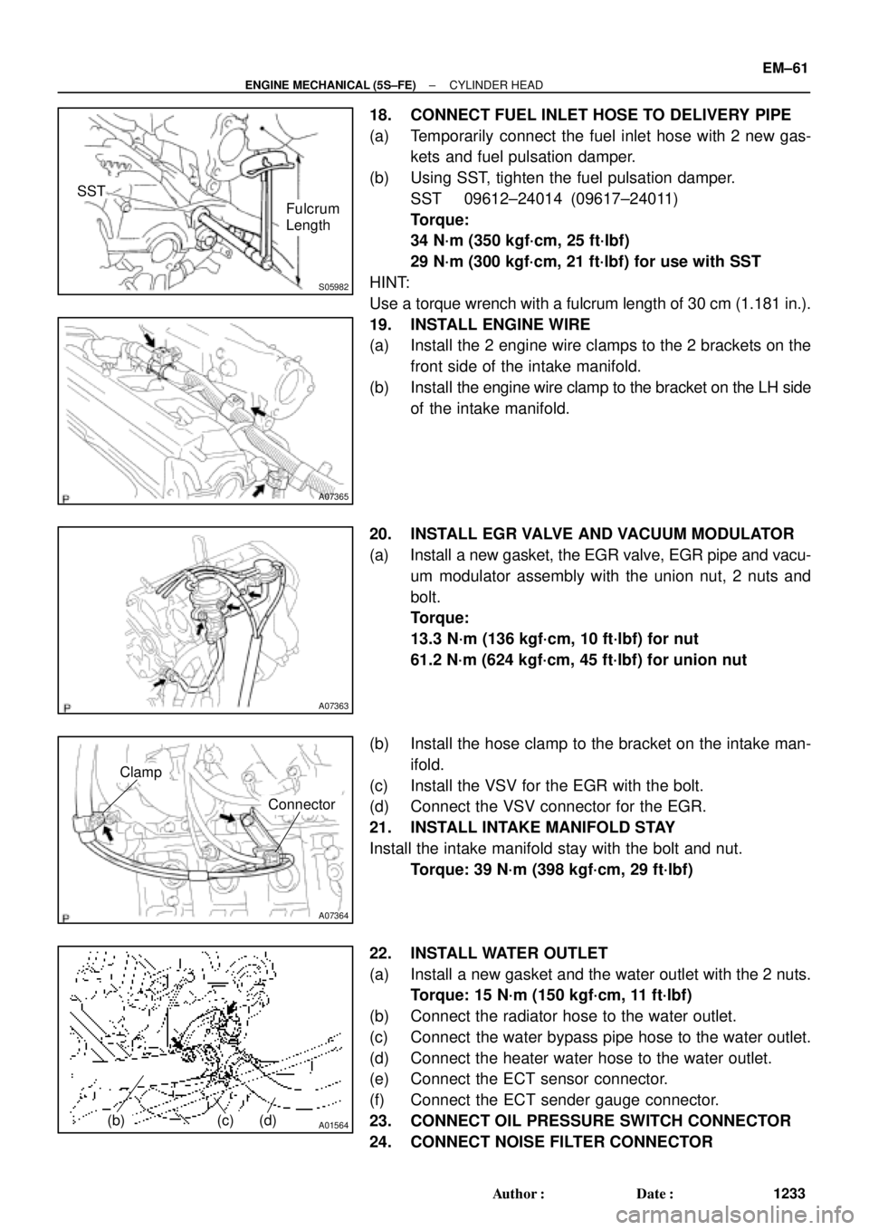
18. CONNECT FUEL INLET HOSE TO DELIVERY PIPE
(a) Temporarily connect the fuel inlet hose with 2 new gas-
kets and fuel pulsation damper.
(b) Using SST, tighten the fuel pulsation damper.
SST 09612±24014 (09617±24011)
Torque:
34 N´m (350 kgf´cm, 25 ft´lbf)
29 N´m (300 kgf´cm, 21 ft´lbf) for use with SST
HINT:
Use a torque wrench with a fulcrum length of 30 cm (1.181 in.).
19. INSTALL ENGINE WIRE
(a) Install the 2 engine wire clamps to the 2 brackets on the
front side of the intake manifold.
(b) Install the engine wire clamp to the bracket on the LH side
of the intake manifold.
20. INSTALL EGR VALVE AND VACUUM MODULATOR
(a) Install a new gasket, the EGR valve, EGR pipe and vacu-
um modulator assembly with the union nut, 2 nuts and
bolt.
Torque:
13.3 N´m (136 kgf´cm, 10 ft´lbf) for nut
61.2 N´m (624 kgf´cm, 45 ft´lbf) for union nut
(b) Install the hose clamp to the bracket on the intake man-
ifold.
(c) Install the VSV for the EGR with the bolt.
(d) Connect the VSV connector for the EGR.
21. INSTALL INTAKE MANIFOLD STAY
Install the intake manifold stay with the bolt and nut.
Torque: 39 N´m (398 kgf´cm, 29 ft´lbf)
22. INSTALL WATER OUTLET
(a) Install a new gasket and the water outlet with the 2 nuts.
Torque: 15 N´m (150 kgf´cm, 11 ft´lbf)
(b) Connect the radiator hose to the water outlet.
(c) Connect the water bypass pipe hose to the water outlet.
(d) Connect the heater water hose to the water outlet.
(e) Connect the ECT sensor connector.
(f) Connect the ECT sender gauge connector.
23. CONNECT OIL PRESSURE SWITCH CONNECTOR
24. CONNECT NOISE FILTER CONNECTOR